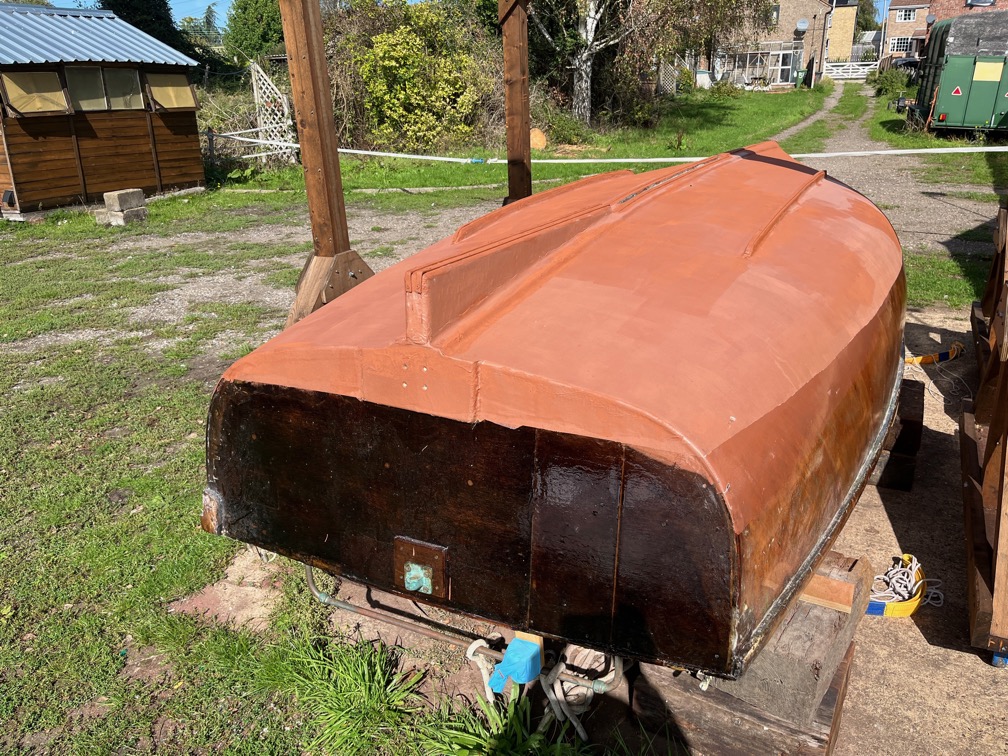
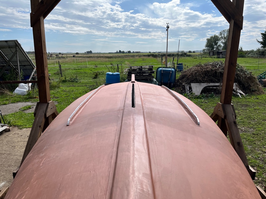
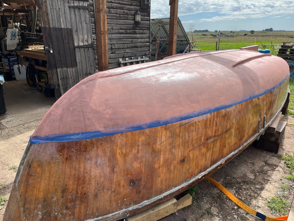
I had wanted to turn the hull today, but it’s too windy.
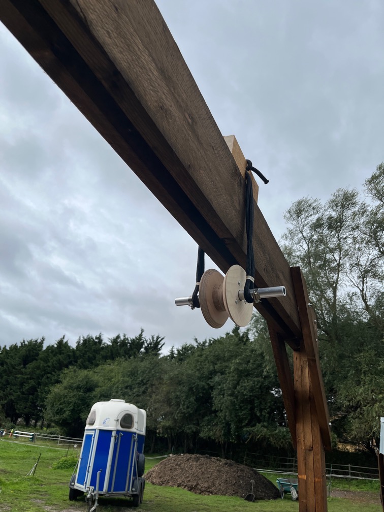
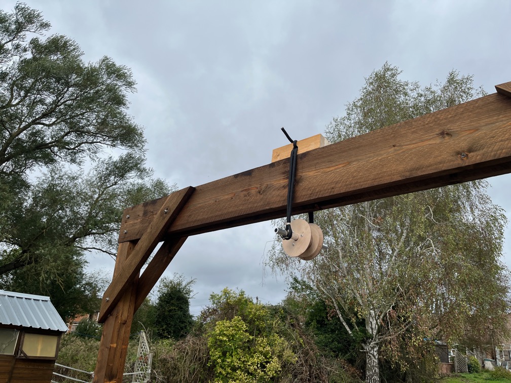
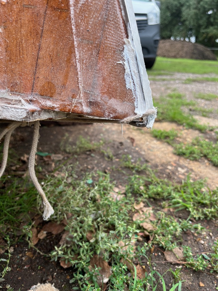
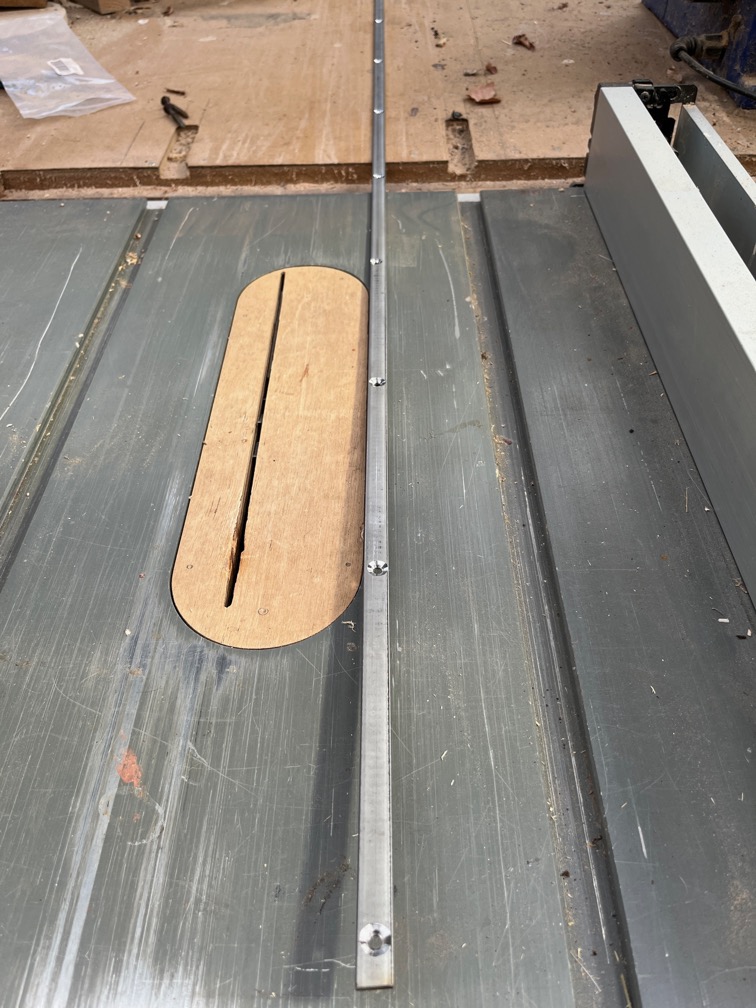
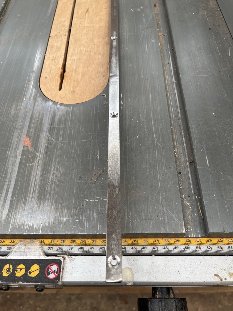
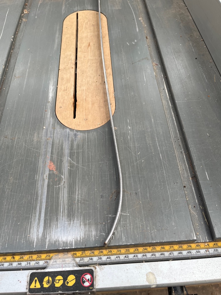
You see, I was unable to drill the 25mm holes in the metal I had cut, my equipment is just not powerful enough to do one, let alone eight, so I had to resort to using rope.
Like this. Perfectly strong enough to take the load but it moves and can move sideways and possibly destabilise the block.
This is manageable, but since this is the first time I’m doing this, I do not want any more possible failure modes and force 6 and 7 gusts of wind count. That is enough to move the boat in the strops and that I want to avoid.
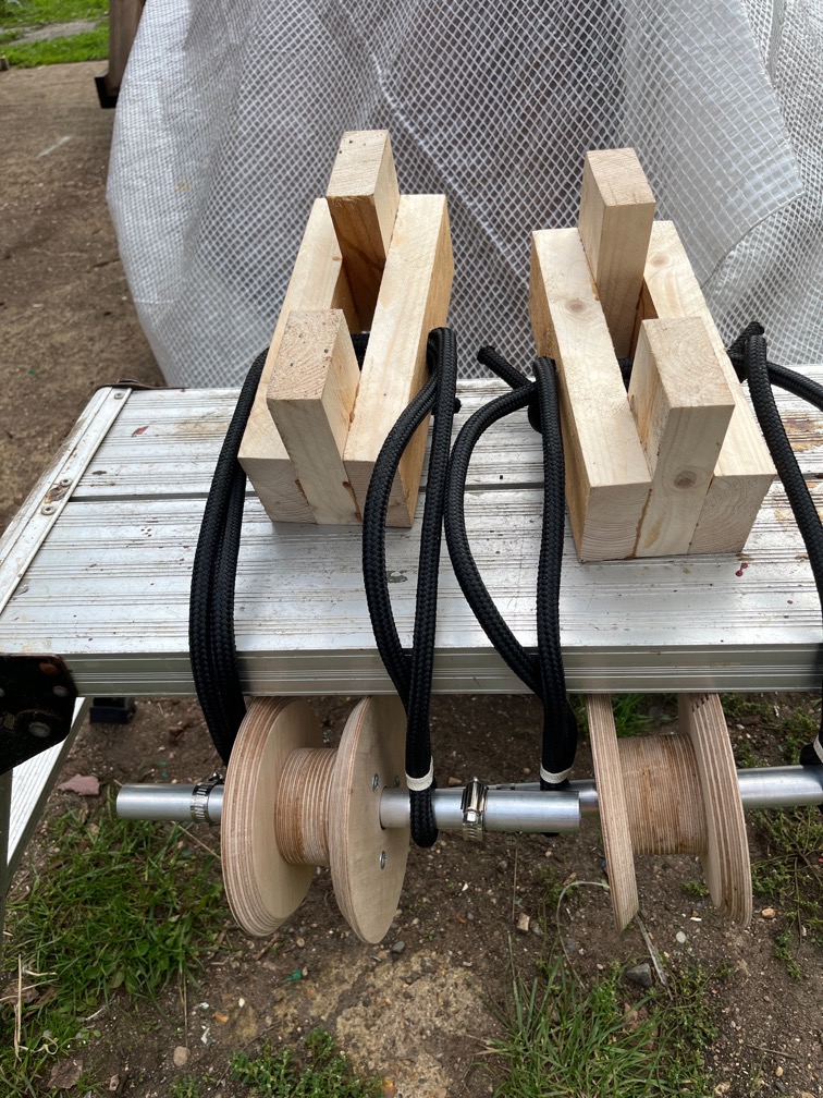
So, having made up the two blocks I put them aside until another day, perhaps tomorrow, when the wind is not so strong. If not tomorrow then Monday and Tuesday look to be quite calm.
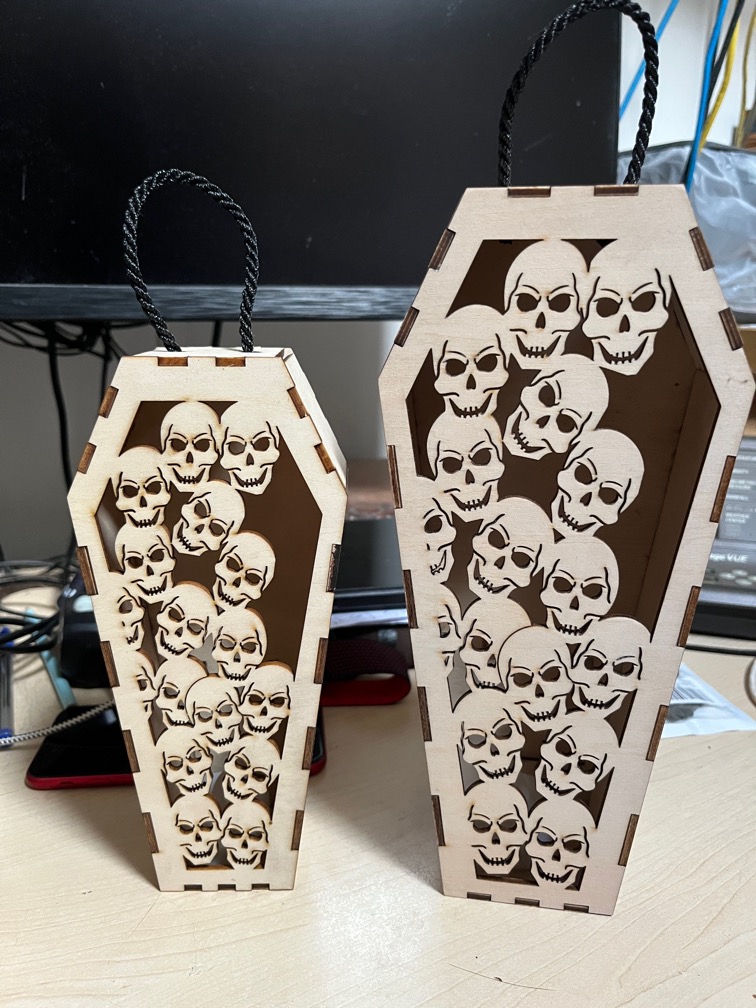
Instead I made these. I’ve not worked on these since Shoal Waters arrived here and I need to make some of these up for an upcoming craft fair. The trouble is that the first two versions required more time to assemble and glue that to do everything else, include the packaging, and that made them not something that I could sell and make a profit.
This version, however, snaps together so there is no assembly, at least not that I have to do and an added bonus is that they ship flat. The biggest issue is the LED tealight. Still, the redesign means that these are now profitable. I have seven different face designs and they are quite popular. The skulls face above being the one that most people seem to want.
Anyway, this was not a wasted day, despite not working on Shoal Waters much.
I did also create a drawing for the metal side pieces I need and send that off for a quote from the same person who made the pieces for Naiad’s tabernacle.
The first task of the day and mid-morning or so, was the dismantling of the tent over the hull.
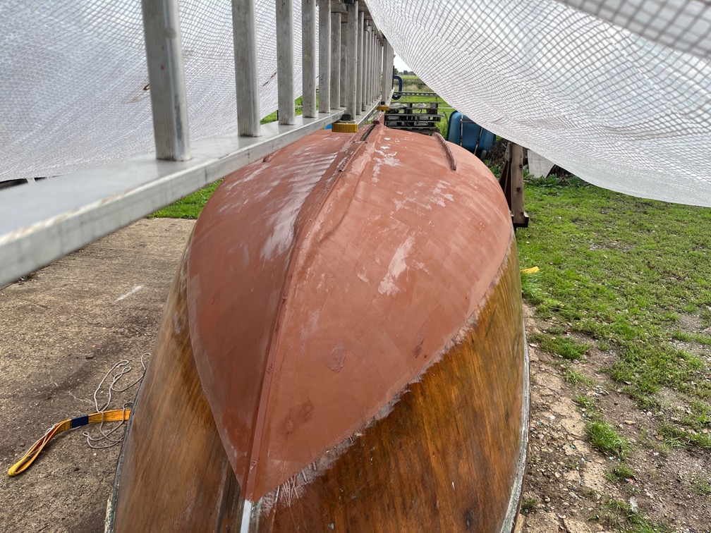
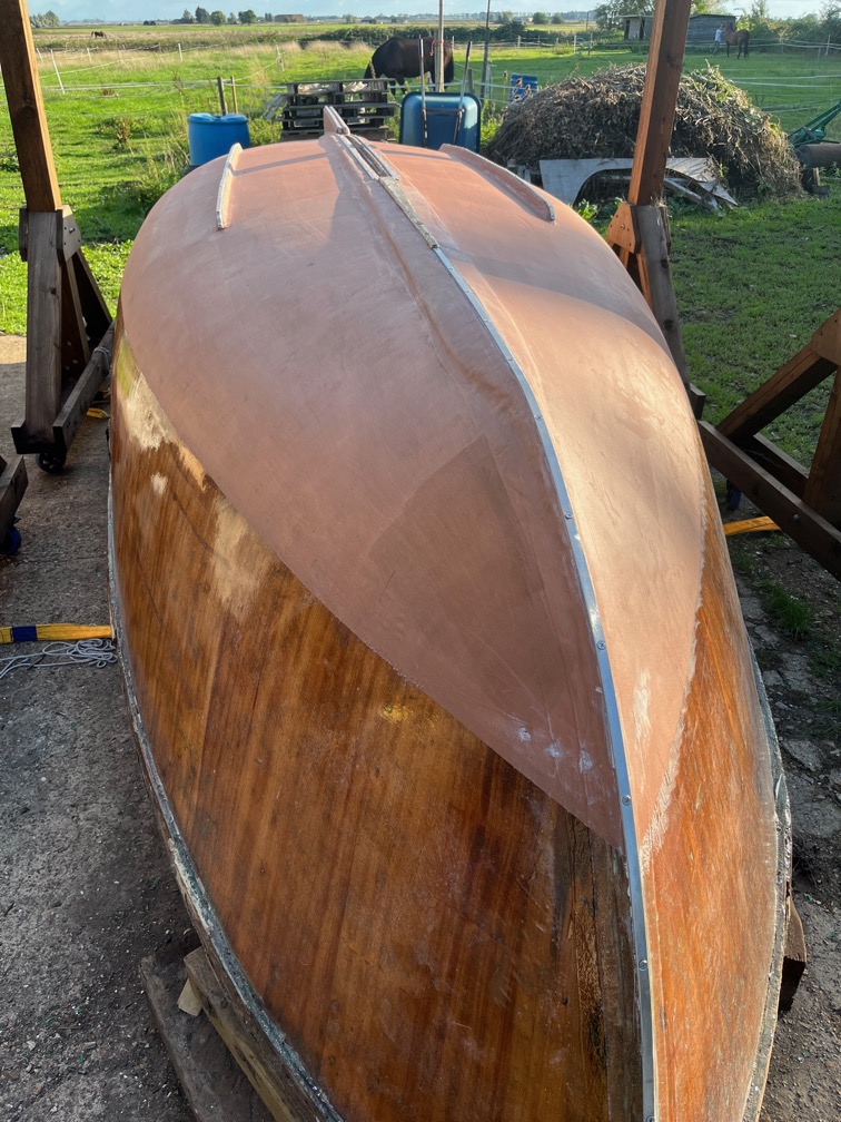
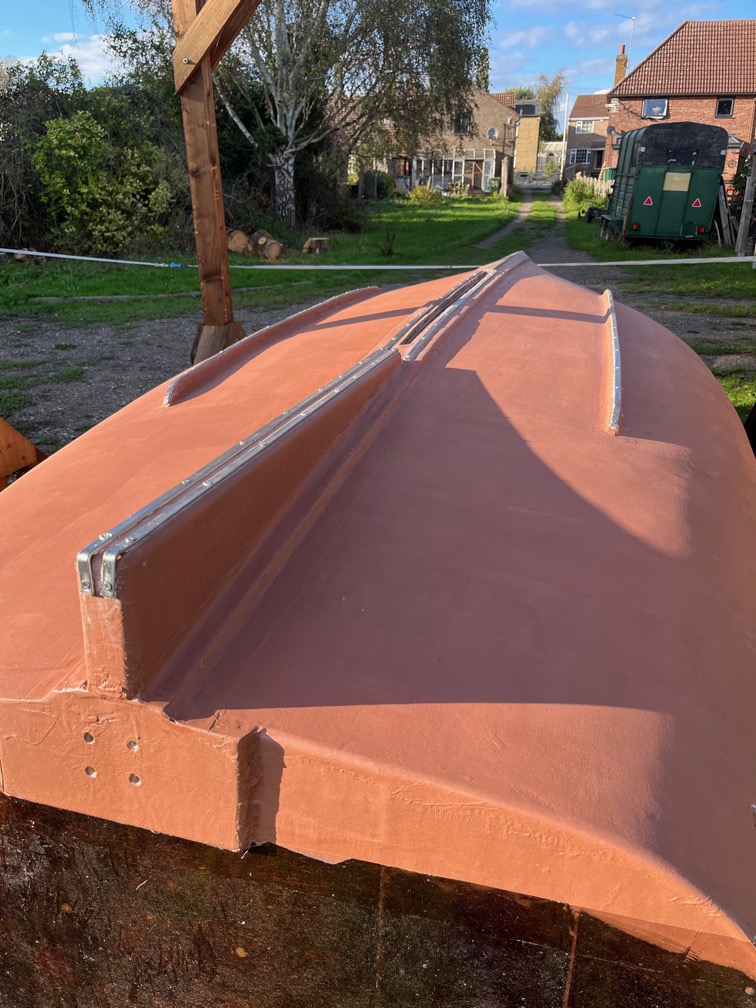
Here she is without the framework around her supporting the cover, and in the light of the morning instead of the early evening.
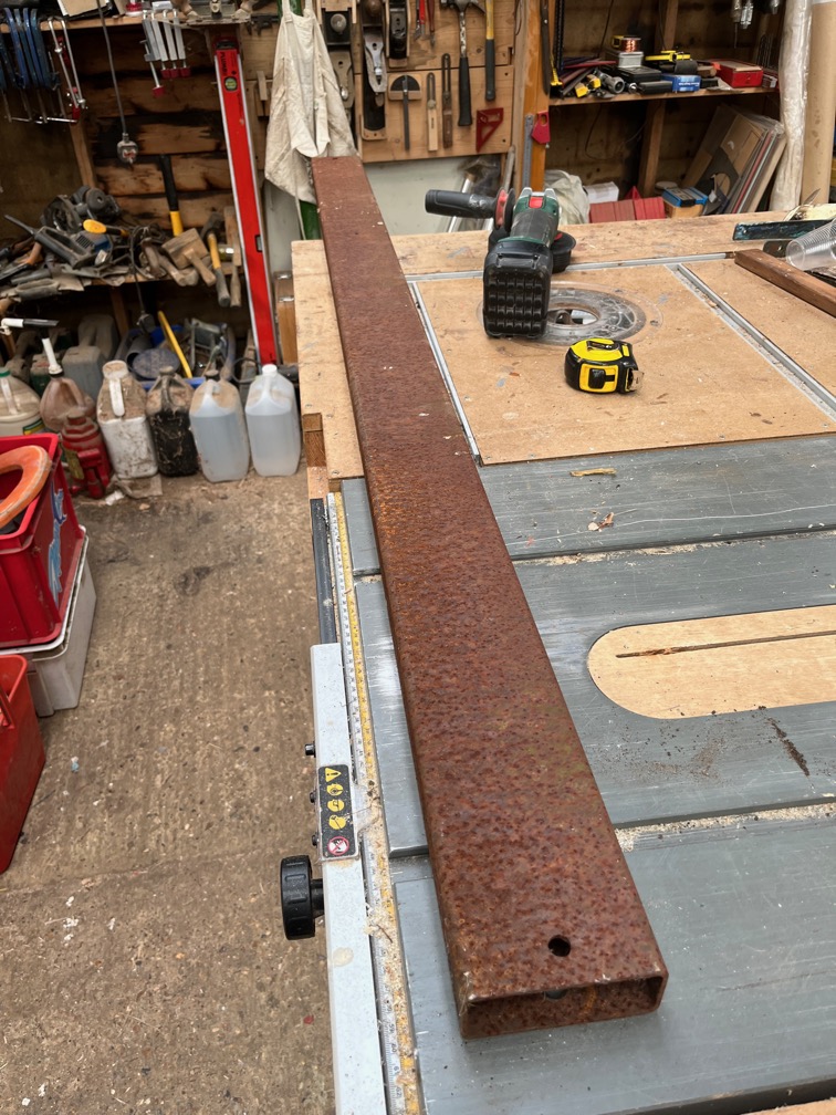
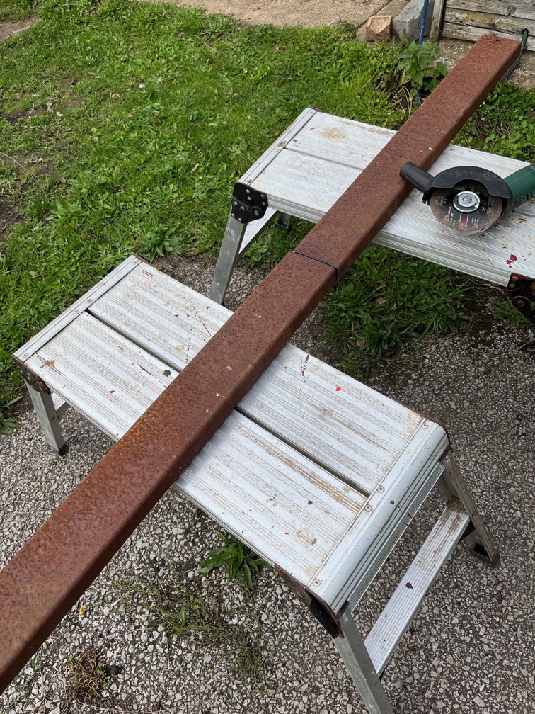
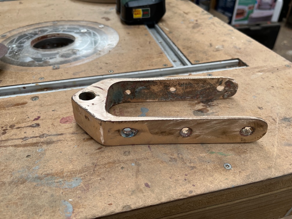
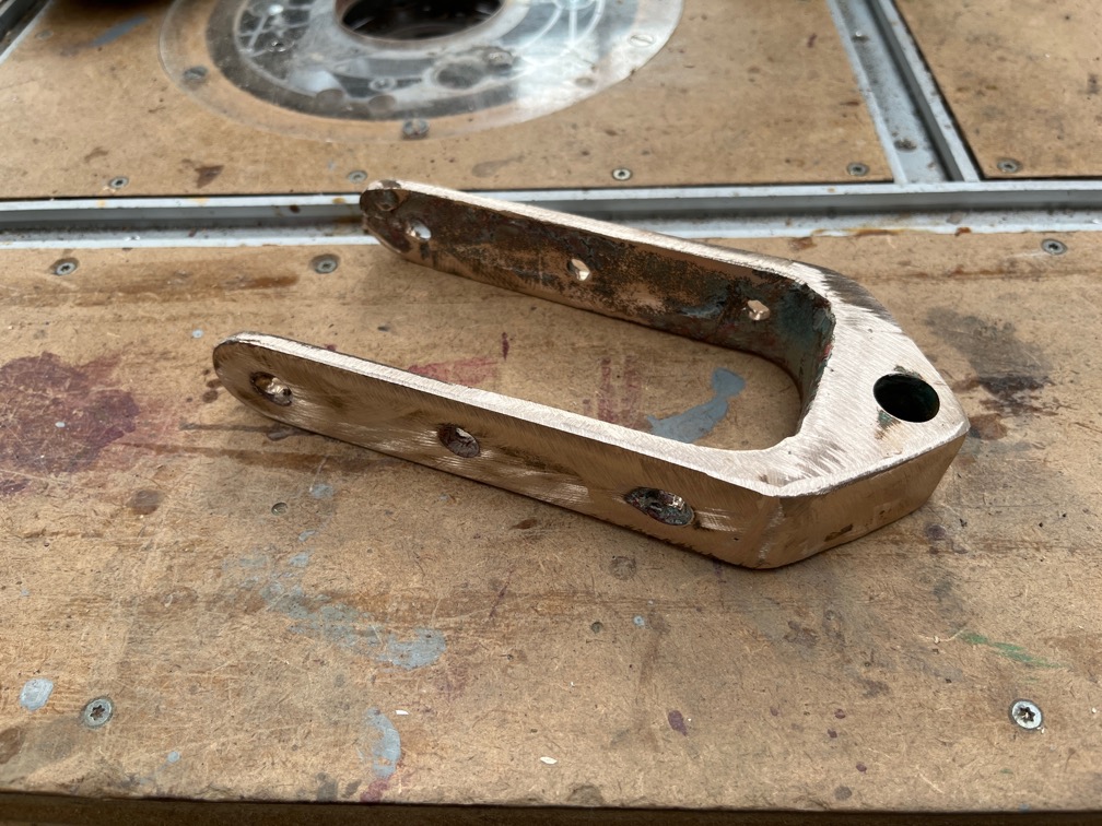
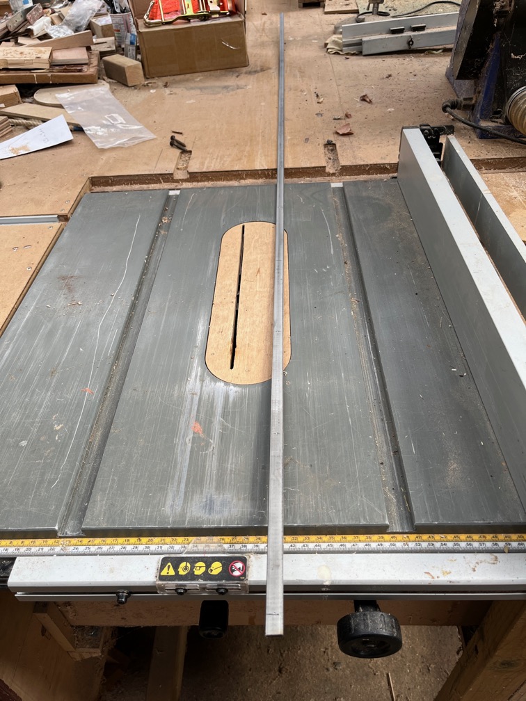
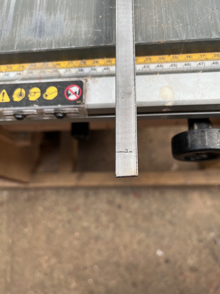
The last part of the inversion blocks is the manufacture of the side pieces that connect the bat over the top of the gantry to the spindle through the pulley proper. The will be made from this length of rectangular section steel that has been laying around the yard for the last thirteen years or so. The first requirement is to cut it in half.
An easy job with a good cutting disk in the angle grinder.
The technique I decided to use was one that I save in a Youtube video made by a gentleman by the name of Mark Reuten, a boat builder in Canada (I think, he has a Canadian accent). He has a business named Mark Reuten Nomad Boatbuilding and the episode to which I am referring is called “Building the Catalina Wherry – Part 25 – Flipping the hull”. Specifically the part that starts here.
Now, the hull in the video is far lighter than Shoal Waters which is why I’m making the blocks so strong, but you can see the principle used.
But the weather forecast said that it should clear up around 13:00 and sure enough, after raining on and off most of the morning, although not hard, the skies cleared and the rain stopped.
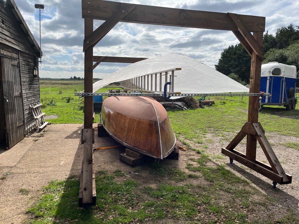
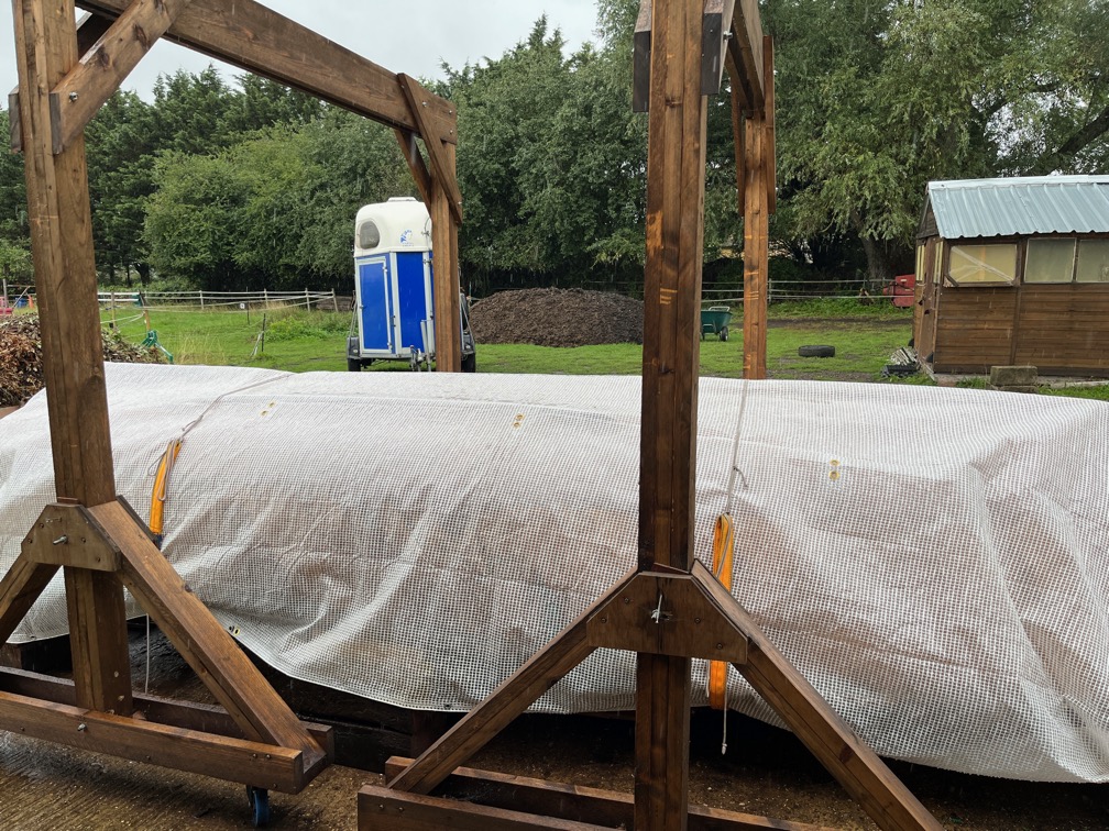
However, I wasn’t going to take the forecast’s word for it and built a temporary shelter under which to work that will also keep off any rain that may fall, thus ensuring that none does.
This is the arrangement this time, with sufficient clearance not only to stop the tarpaulin from touching the hull but also to allow enough space for me to work under it.
Worked well.
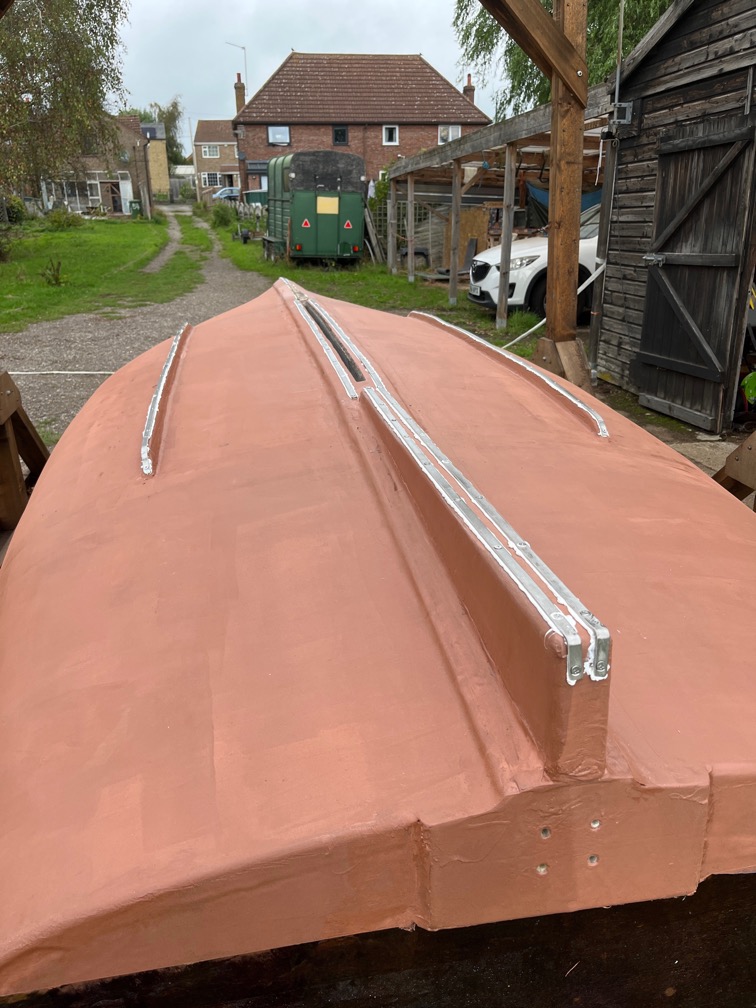
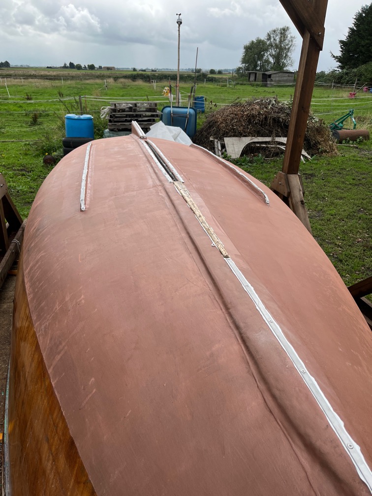
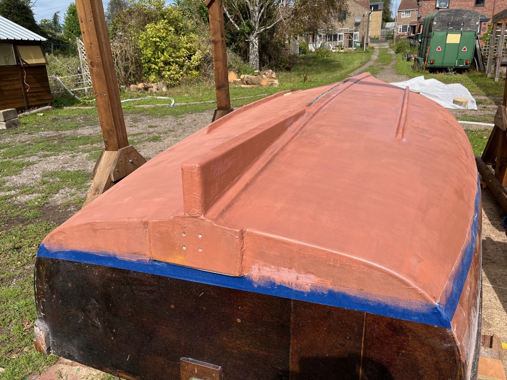
This is the result after the second copper epoxy coat. All the keel bands have been liberally coated and since I mixed up far more than I needed, I spread the remainder around the hull with a roller, concentrating on those areas that looked a little thin.
What it quite interesting is the colour of the copper powder used, from a different supplier, is a different colour to that used in the first two coats. Not that it matters since it will all be underwater and will go green quite quickly.
Now all that remains is to work on the inside of the bottom of the centerplate slot, removing any sealant squeeze out and making sure that there are no gaps anywhere or rough spots. However for this work to be done I need Shoal Waters to be on her side. First one side and then the other and for two reasons. The first is that I can’t access the slot as she is now, it’s too far away from where I can stand and too high. The second reason is that I will need to put in some epoxy in places and having the hull on its side will mean that the epoxy is pulled into the place where it is put, instead of dripping through the slot and into the cabin.
So, the next task is to finish the inversion blocks.
I thought today would be the day that I started, and possibly completed, the last part of the epoxy application that required me to have the boat uncovered. Alas, halfway through the day the weather forecast changed, rain was forecast and it was correct. The rain, not much and intermittent, began shortly afterwards.
I need a warm dry day to apply the epoxy and then, between six and twenty-four hours later, another warm dry period to apply the second coat. The forecast indicates that this might happen tomorrow or Friday.
So for today, I needed to find other tasks that can be carried out in the workshop.
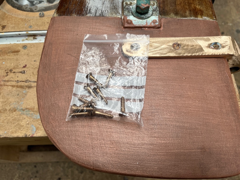
The first task became obvious when the ten silicon bronze screws I ordered a few days ago arrived in the post.
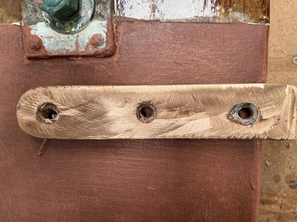
I put in three of the screws using the holes I had already drilled but widened a little to suit No.10 screws.
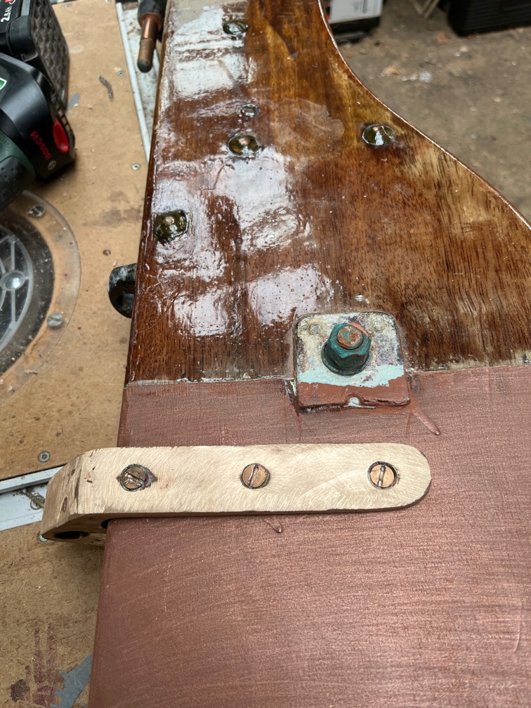
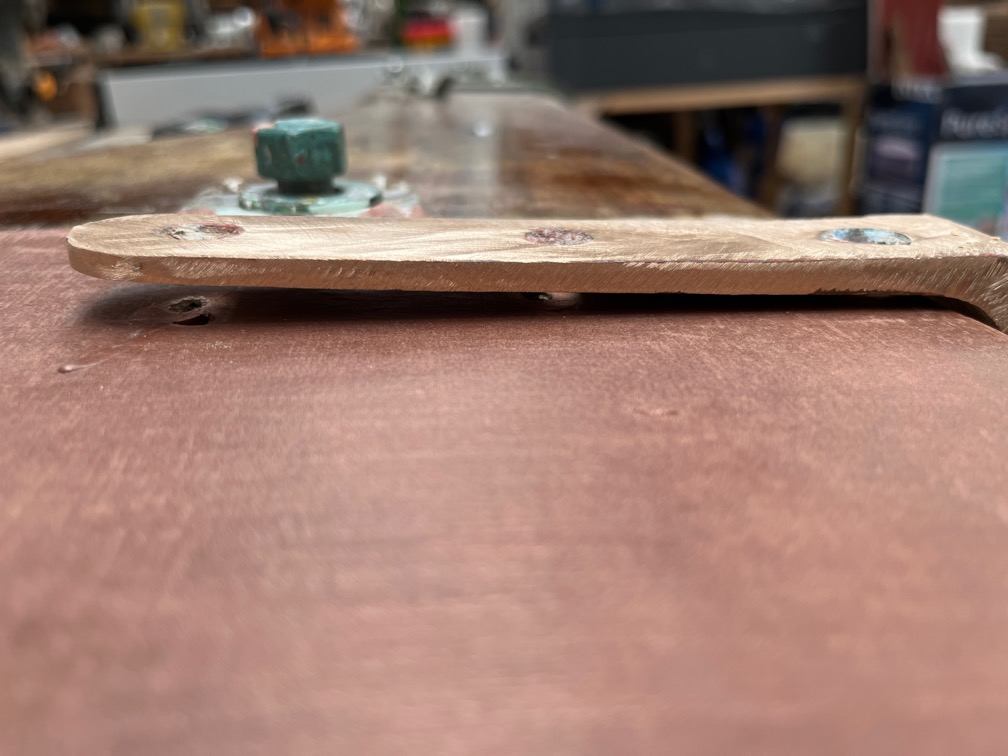
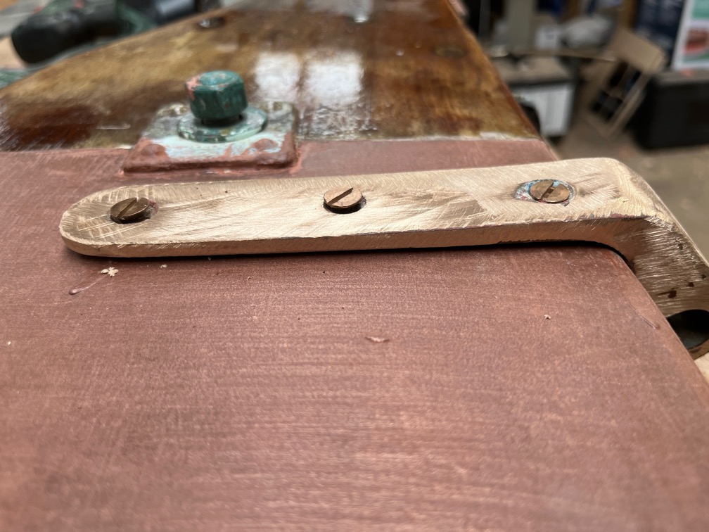
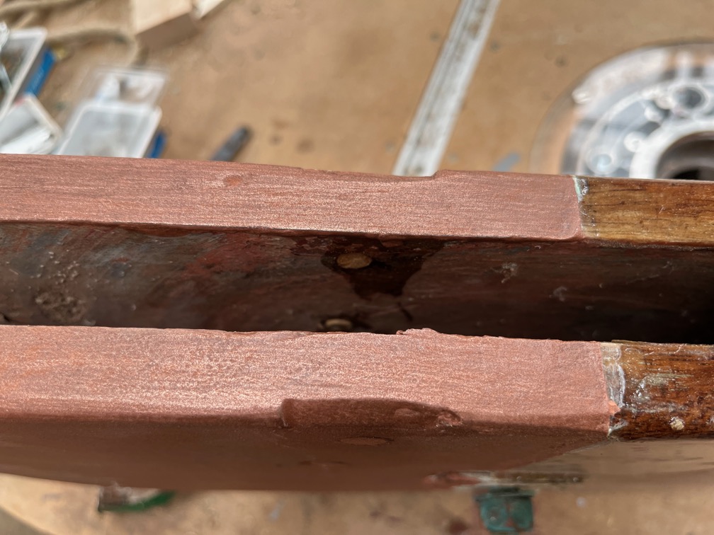
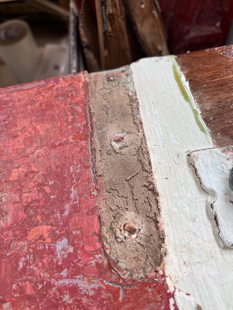
When tightened down such that the tang touches the stock, the other side stands clear of the surface. This explains why there was so much filler on both tangs.
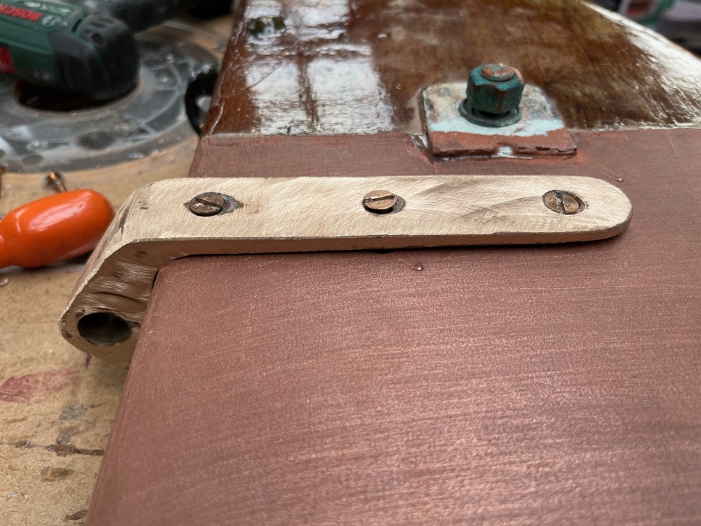
It also meant that the screw holes were misaligned. The solution to this was to loosen off the three screws, allowing the fitting to move around, partially screw in the screws on the side shown and then tighten them down carefully, but not too tight.
I used a screwdriver bit in a brace for this after finding out that the cordless screwdriver slipped out too often and partially damaged the slot in the screw head. With these things costing around £1 each when you include the postage, damaging them was not something I wanted to do if I could avoid it.
Here the screws are loose on one side…
…and a little loose on the other and as you can see, the fit is much better.
I’ve left it like that for the moment whilst I decide whether to put in a filler piece of thin wood, to use the Sikaflex sealant or just to tighten the screws up carefully and not bother with any kind of filler at all.
At the moment I’m tending towards the Sikaflex.
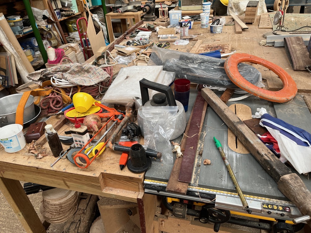
After that I started a task that I have been putting off for over a year now, since Shoal Waters first arrived and was put into the Hay Barn. I took out a lot of the bits and pieces that came with her, put them into two plastic boxes by her stern and then left them there.
They have needed to be sorted out since them and today I finally got around to doing just that. Well, the start of that.
I sorted the items out into three piles. rubbish, keep and belongs to Tony (the previous owner), reading glasses, tin whistle and the like. The spiders were put outside.
There was a lot of rubbish.
What you can see in the photo above is the non-rubbish stuff. This will need to be further sorted in other piles which include “keep to go back onto the boat”, “keep but don’t put back on the boat” and “what the heck is that for?”. There may be other categories, but those are the ones I can think of for now.
That orange ring, by the way, is not a life ring, it’s a toilet seat to put on the top of a bucket. The bucket was not part of the inventory!
Time for a cup of tea.
I went out around 20:00 hours to feed the outdoor cat, close up the workshop and generally check around the property, something I do every evening, and there was a heavy dew forming already. The sky was clear and you could feel the chill in the air.
The main task of the day was to clean up the remaining sealant so that the keel bands are ready for the next stage. After 24 hours the sealant was hard enough to make the job a little easier than yesterday but even so it was not a quick job.
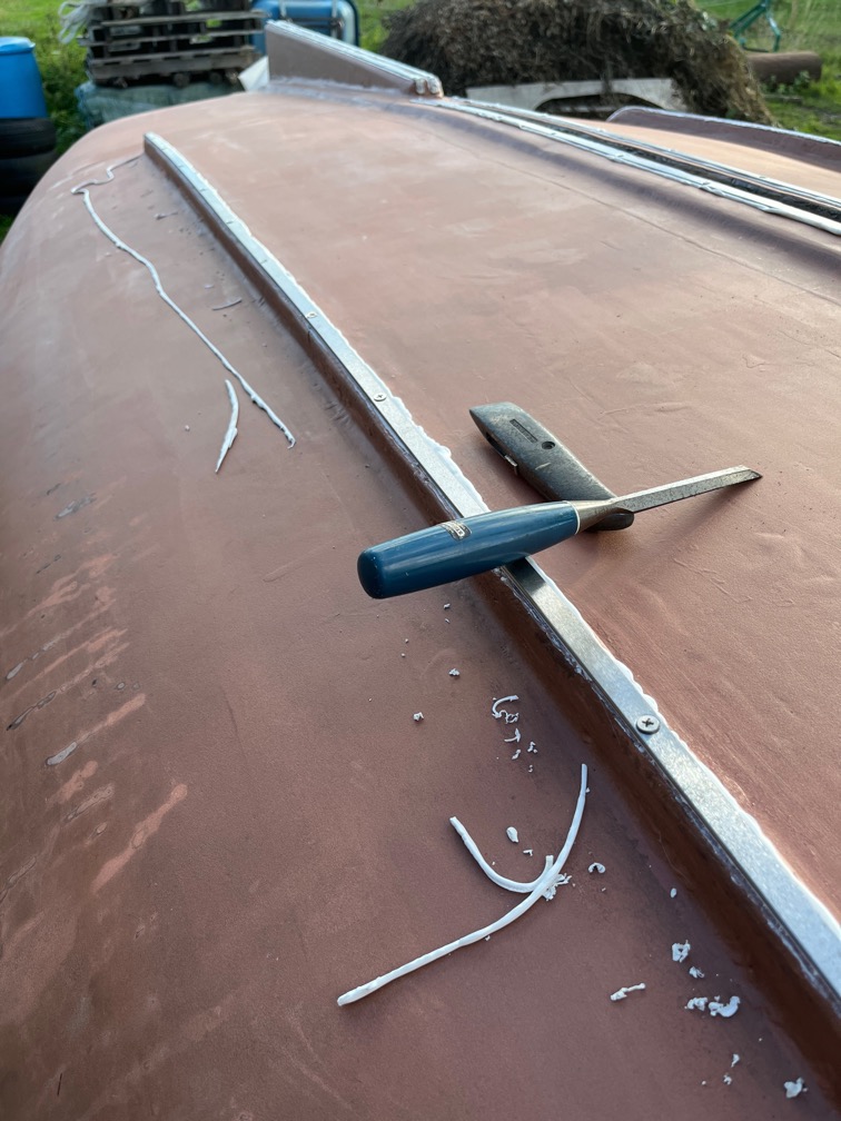
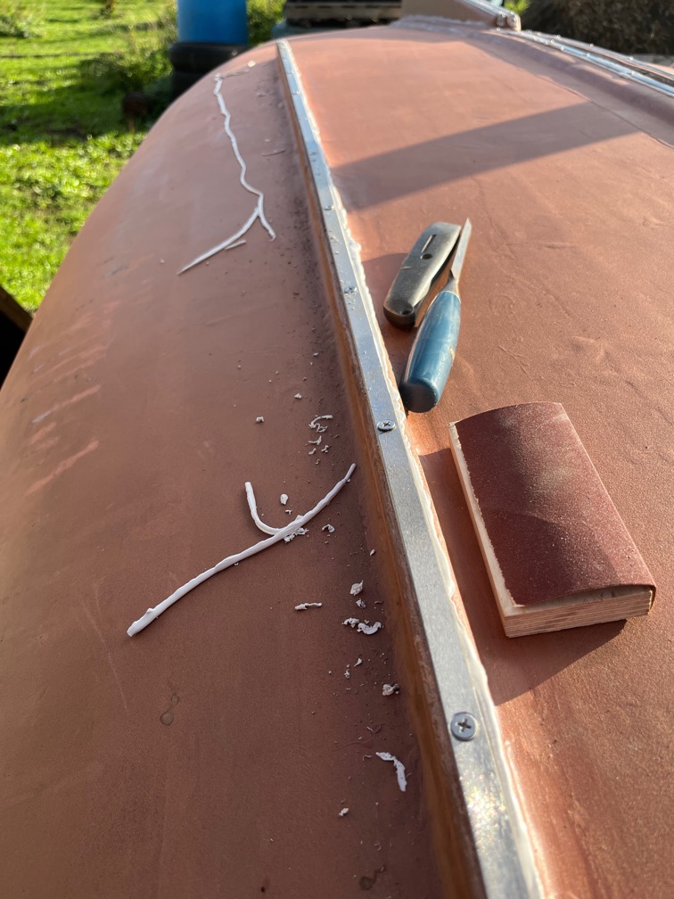
After nearly two hours of cutting, chiselling and sanding, all carefully, this is the result.
Nearly all of the excess squeeze out has been removed. There are a couple of bits that I can’t really get to so these were left for now and I’ll think about how to get a sharp edge into those tight spots.
The other task that has been waiting for a while is the assembly of the pulleys.
Not a difficult job, I just hadn’t gotten around to it.
That’s all for today. I’m definitely beginning to flag.
This morning started warm and very, very humid. Most uncomfortable. I took the cover off the boat and found that despite the cover, some of the hull was damp and especially in those areas where the dew that had collected on the top of the cover spilt as I removed it!
The first task after that was to remove all the screws from yesterday and then let the hull stil in the warm air to dry.
Later in the day I took a lunch break and worked on the keel bands again.
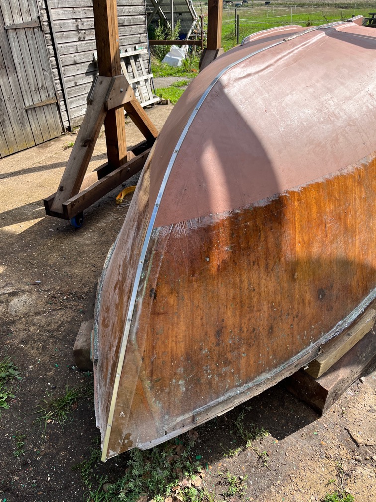
Each of the bands is now bedded in Sikaflex 291i and held in place with the correct number of correctly sized screws.
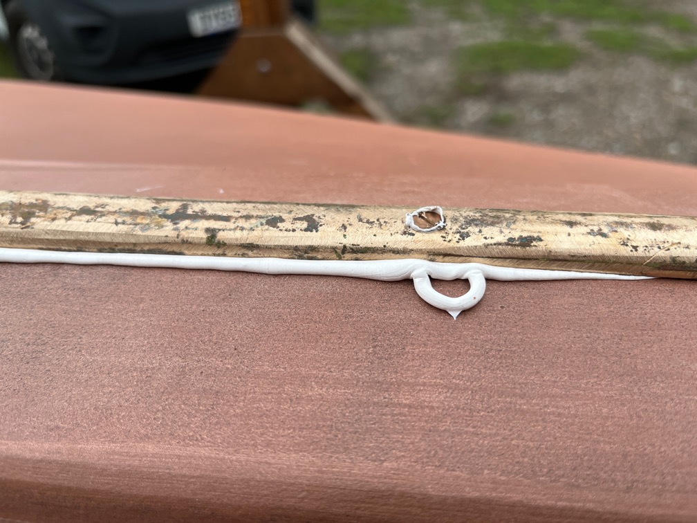
The trick with this stuff is to wear nitrile gloves and boiler suit, the sealant gets everywhere, apply the sealant as a thin bead moving slowly long the length of the section and never, never attempt to correct mistakes.
Like this. Trying to fix this will just smear the sealant all over everywhere and make a mess and won’t get the stuff off.
This is an example of where I had no choice. There was a significant gap between the bead and the stem that no amount of bending could fix, so I had to fill that gap with sealant applied with a mixing stick. As you can see, it smeared even though I was being ultra careful.
Later in the evening I set about removing the excess sealant. A sharp utility knife is run alongside the keel band cutting down, but not too hard as to damage the surface . Then a sharp chisel is run along the top of the surface to peel away the cured sealant in strips.
Finally, any remaining pieces of sealant are sanded away. Here I used 240 grit. As you can see, the result is very good. Far better than you would get if you tried to clean this stuff up when it was still sticky.
Having said that, the sealant was still a little too soft, so I stopped doing that and will carry on tomorrow.
I awoke to the sound of steady rain this morning and by the time had gotten up and done the necessary, there was no sign of the rain letting up. It was warm enough, just wet. Not that a decent soaking rain, which this was, was not welcome in a general sense, it just meant that the plans for the day had to be changed.
Work moved inside the workshop instead of outside.
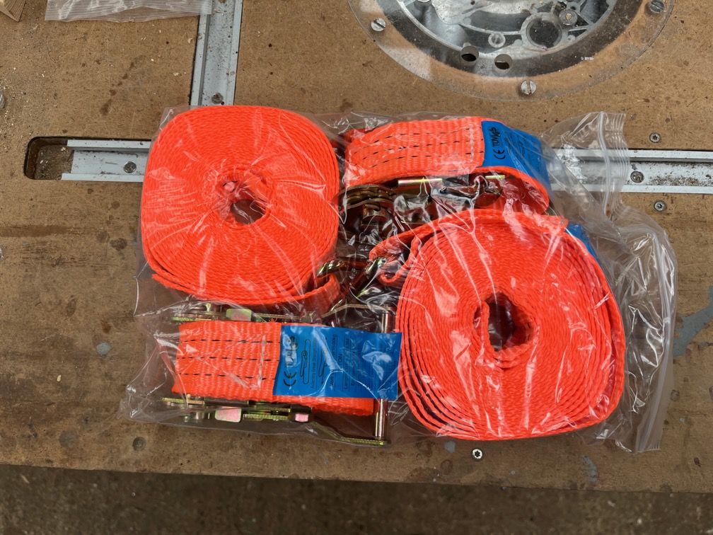
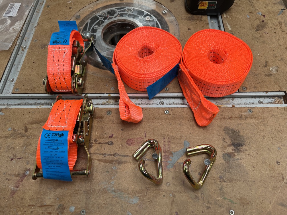
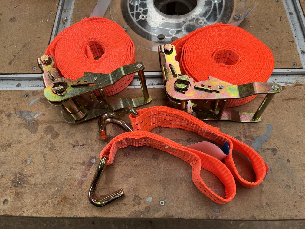
The first task was to convert the three remaining ratchet straps from hooked to non-hoked.
This isn’t difficult, you just use a hacksaw to cut the hook on the strop end and bend the hook so that you can remove it, as shown.
The strops are then put onto the ratchet replacing the short strop and hook st give the desired result.
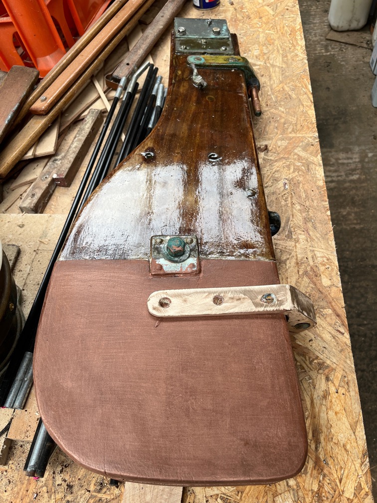
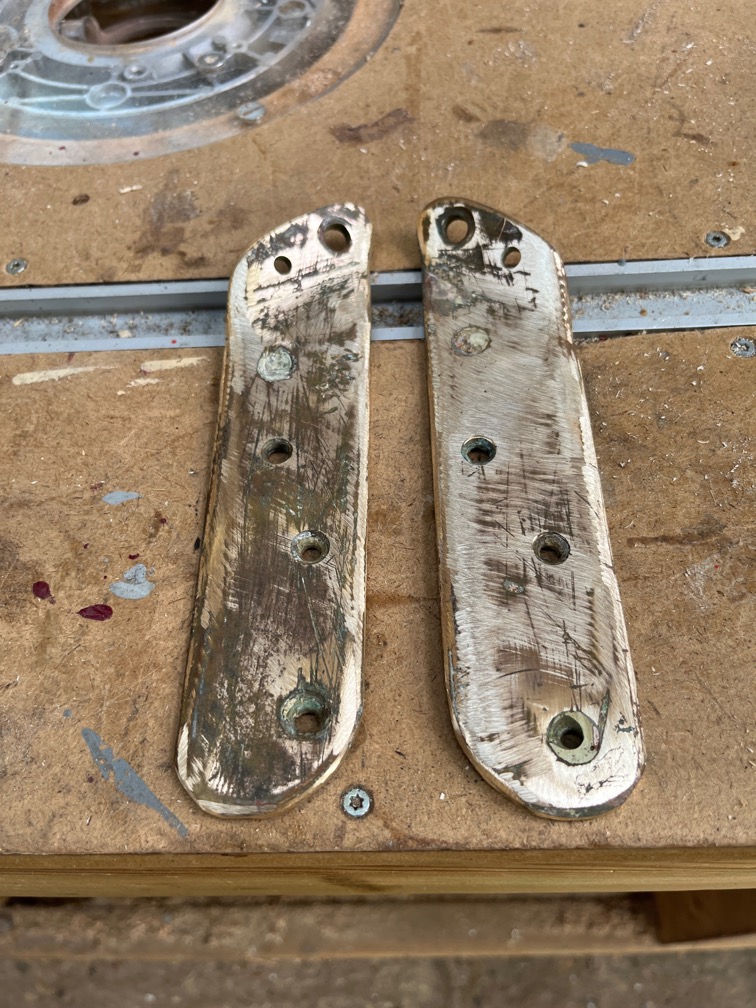
The next task I choose was to clean up the rudder gudgeon fitting prior to putting it back on the rudder stock.
I left a rough finish to give a key as this will be coated in copper epoxy.
The position of the fitting was marked by two notches in the rudder stock which made it fairly easy to get it back in the correct position.
The only issue was that I didn’t have the correct sized bronze screws to fit it together. So I put two smaller screws in to hold the fitting in place for the moment and ordered a pack of ten No.10 1″ screws. Once these had arrived I can fix the fitting in place more securely.
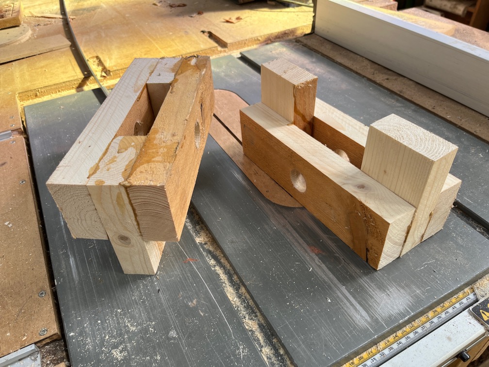
After that I cut up a piece of scaffold plank to make two fittings for the inversion blocks. Then I took a break.
The rain has stopped and the dark gray clouds are being slowly replaced by ones that do not look like they will drop rain everywhere.
Time for a cup of tea.
Sure enough, the weather did improve and the sun came out, so it was back to work.
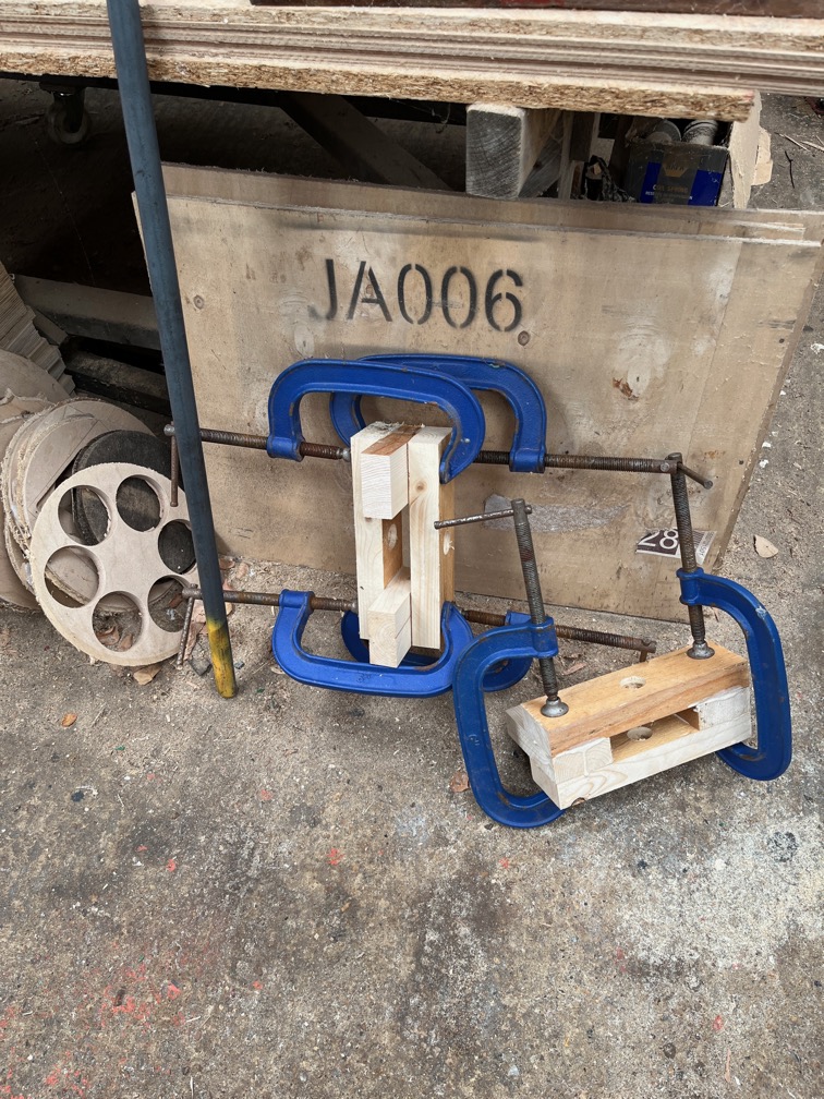
The supports for the inversion blocks were taken out of the cramps and put aside until needed.
The two halves of the bobstay stem fitting were cleaned up ready to be re-attached.
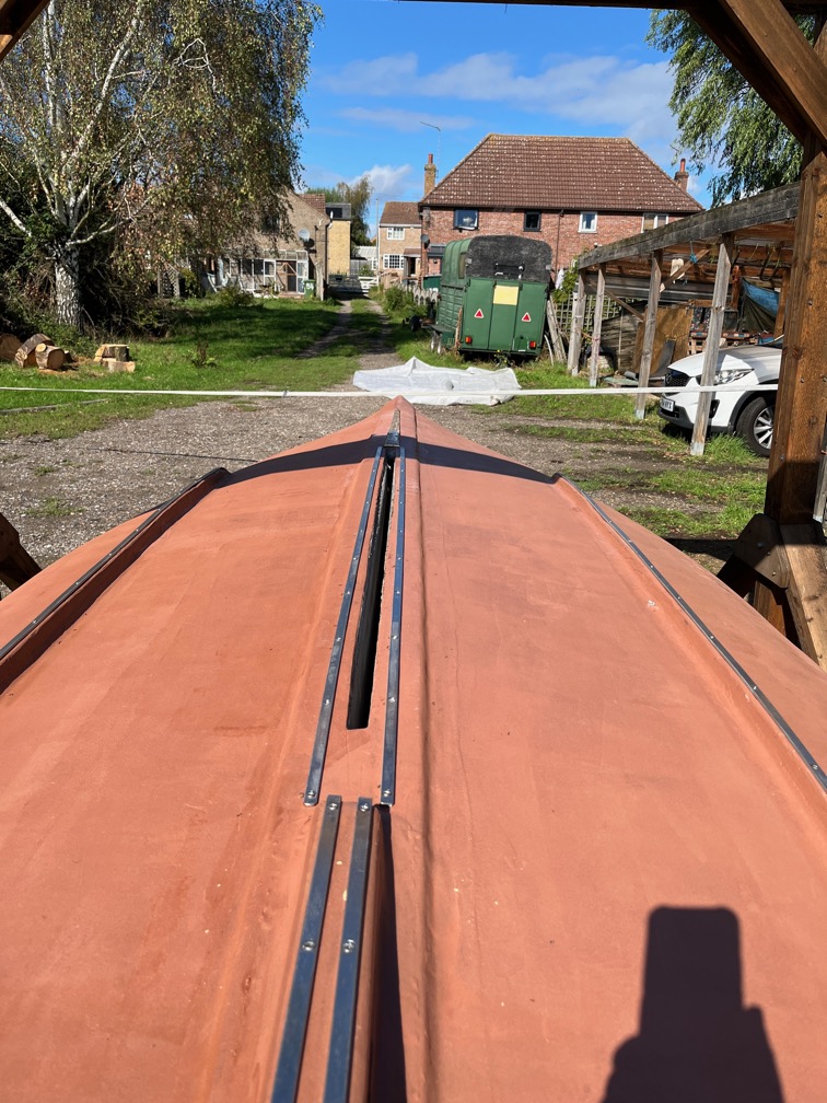
The two keel bands either side of the centerplace slot were made and dry fit.
The final keel band, for the ste, was also made and dry fit.
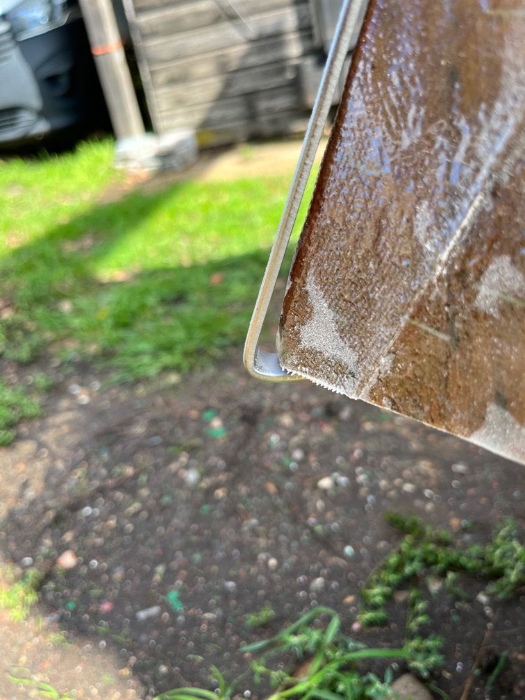
This was a little awkward as the end was designed to fit over the top of the stem which made for a very acute angle. The band will be pulled against the stem with a line or pressed with a wooden batten but for now, we wait for the correct screws to arrive. At which point all the bands will be removed, sealant applied and squirted down the screw holes and the band refitted with all the screws, not just half of them !
With the warm and dry weather continuing to hold for the last week and for the next few days, according to the forecast, I could continue with the final underwater hull work before Shoal Waters could be turned back the right way up and put back into the hay barn.
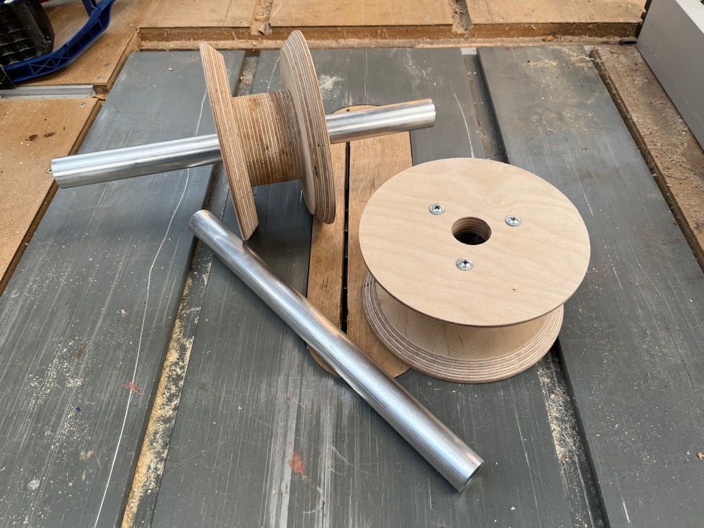
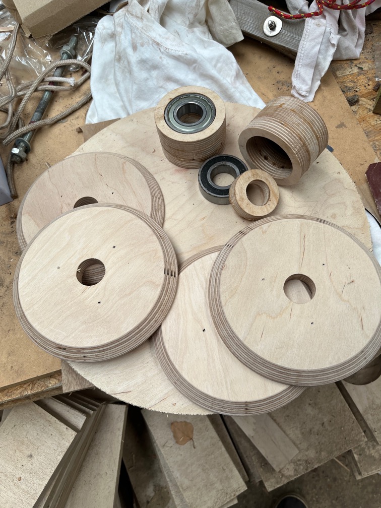
I spent a few days during the week using the CNC Router to make these. Once assembled these will form two large bearings over which a open ended ratchet strap will run that will make the task of turning the hulls over a much easier process than is it now. More on that in a later post when the inversion is carried out. Today’s task for these bearings took a couple of hours, so..
Time for a cup of tea.
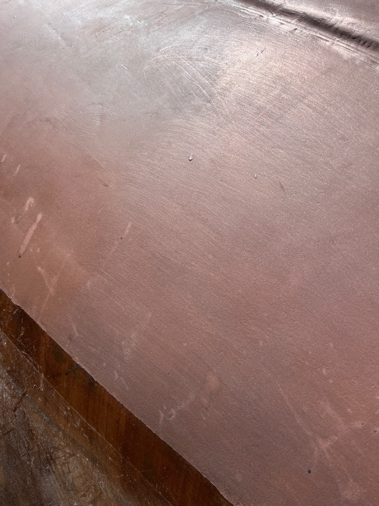
I took the stainless steel scrubbing pad to part of the copper epoxy scraping off the top layer of the epoxy and exposing some of the copper particles embedded within it. It’s not easy to see here but the slightly lighter and more metallic looking surface on the right hand side of the image is the scrubbed bit. Thankfully it is not difficult as the scrubbing pad acts like a lot of small, sharp scrapers made of stainless steel.
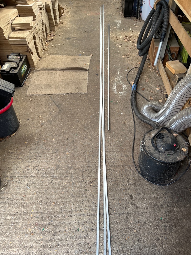
These are the 316 stainless steel flat bars from which the keel bands will be formed. Stainless steel, as mentioned in a previous post, instead of the expected bronze because of the staggering cost of making the bands out of bronze.
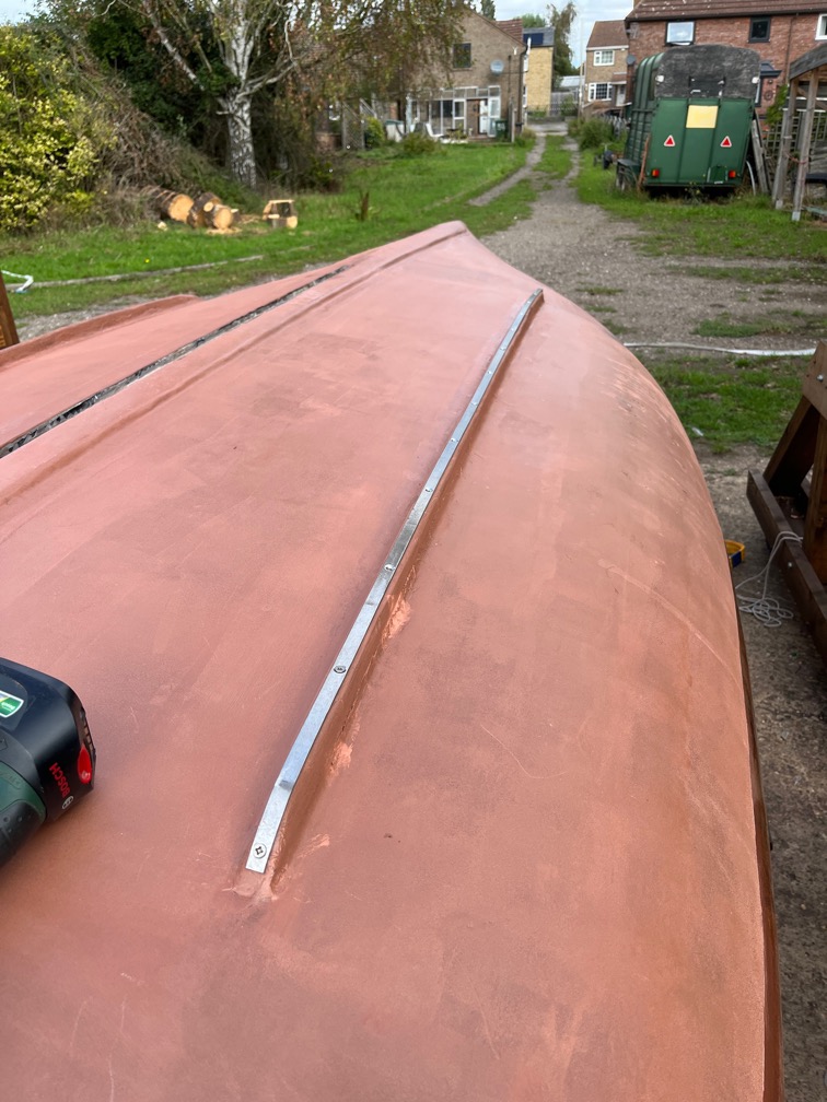
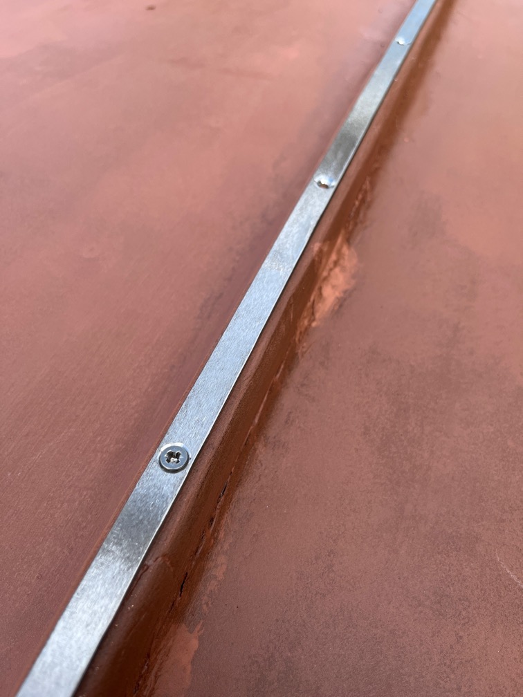
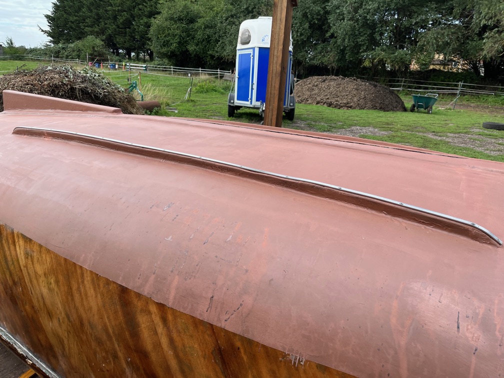
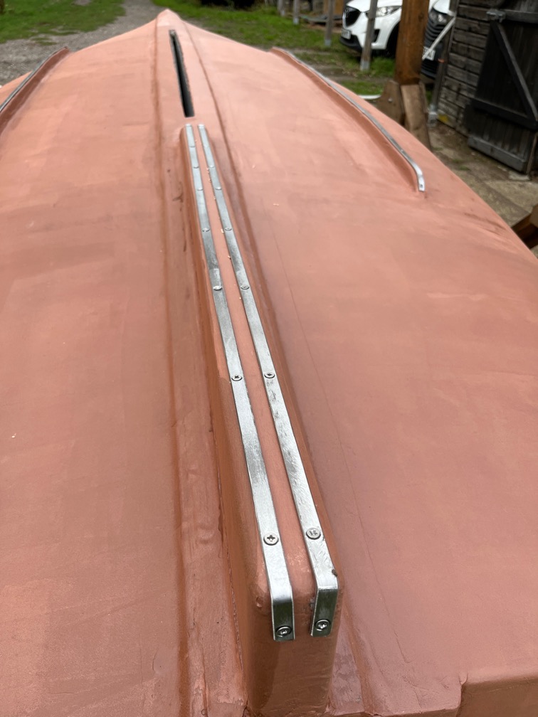
This is one completed and dry fit to one of the bilge runners. Dry fit as I don’t have the 316 stainless screws to hold the bands to the hull and have used what I do have until the proper one arrive. Hopefully that will be tomorrow.
I have only used as many screws in each band is required to hold it in place since my stock of correct length and diameter screws is limited.
That is still a lot of screws as the runner is not an even surface as you can see.
This first one took another hour and a half and, guess what?
Time for a cup of tea.
The process of making each band is tedious but straightforward. A length of stainless steel is cut, having carefully measured at least twice.
The band is marked where the screws will be places, every 150mm or 6″ more or less, and a punch used to make a small dent in the steel to guide the drill bit.
The holes are drilled and counterbored and the top “corners” of the bar chamfered using a bench grinder.
Both the top and bottom faces were abraded on the belt sander to give a good key.
All but two of the bands needed to be shaped, like the one above. This was a case of hammering the band over the horn of the anvil until the correct curve was obtained.
Then the band was dry fit.
Time for a cup of tea.
Rinse and repeat for the two bands on the skeg. Including the cup of tea.
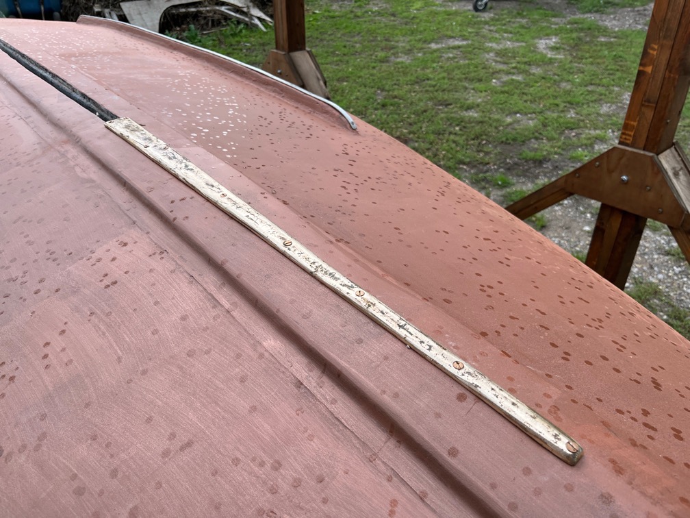
I sanded the old bronze keel band, or what remained of it and used bronze screws to fix this to the keel.
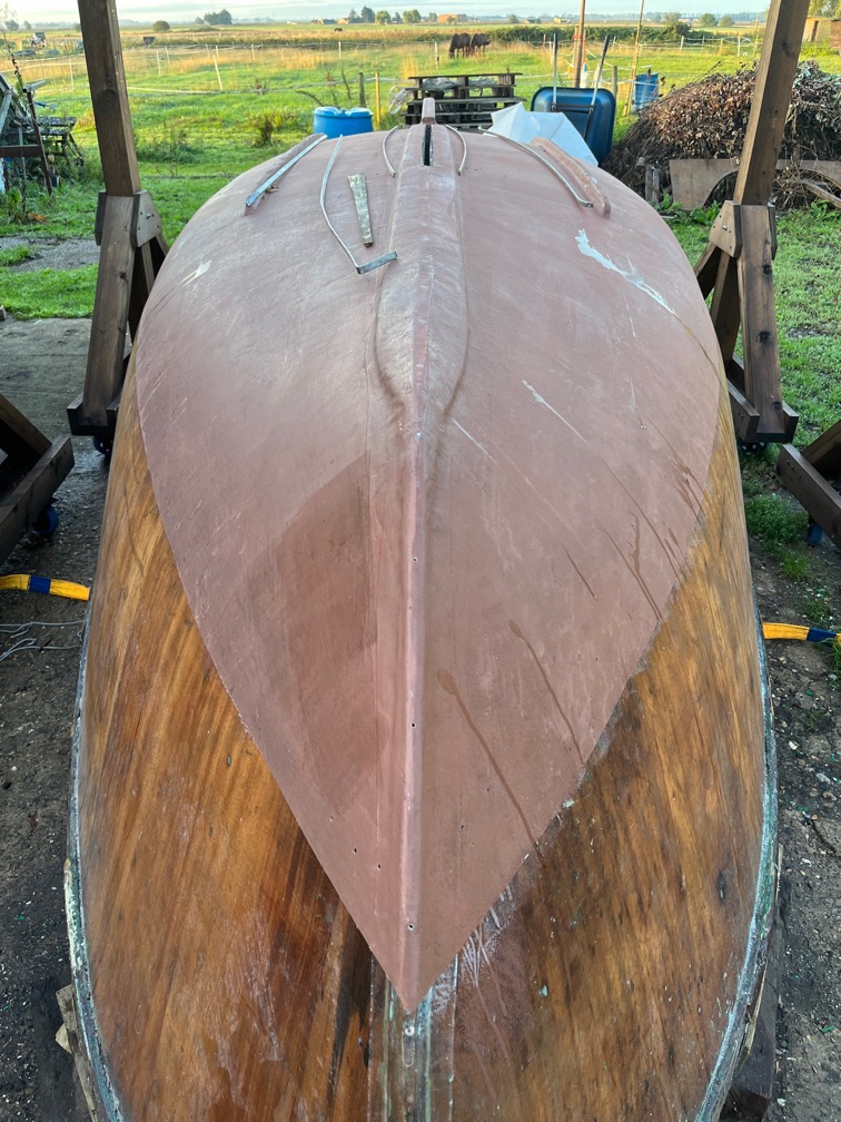
At this point, as you can see but the spots of water on the hull, it started to rain, so work stopped until the morrow when the remaining pieces will be done. Two either side of the centerplate slot and one from the bronze above forward and up the stem to the deck.
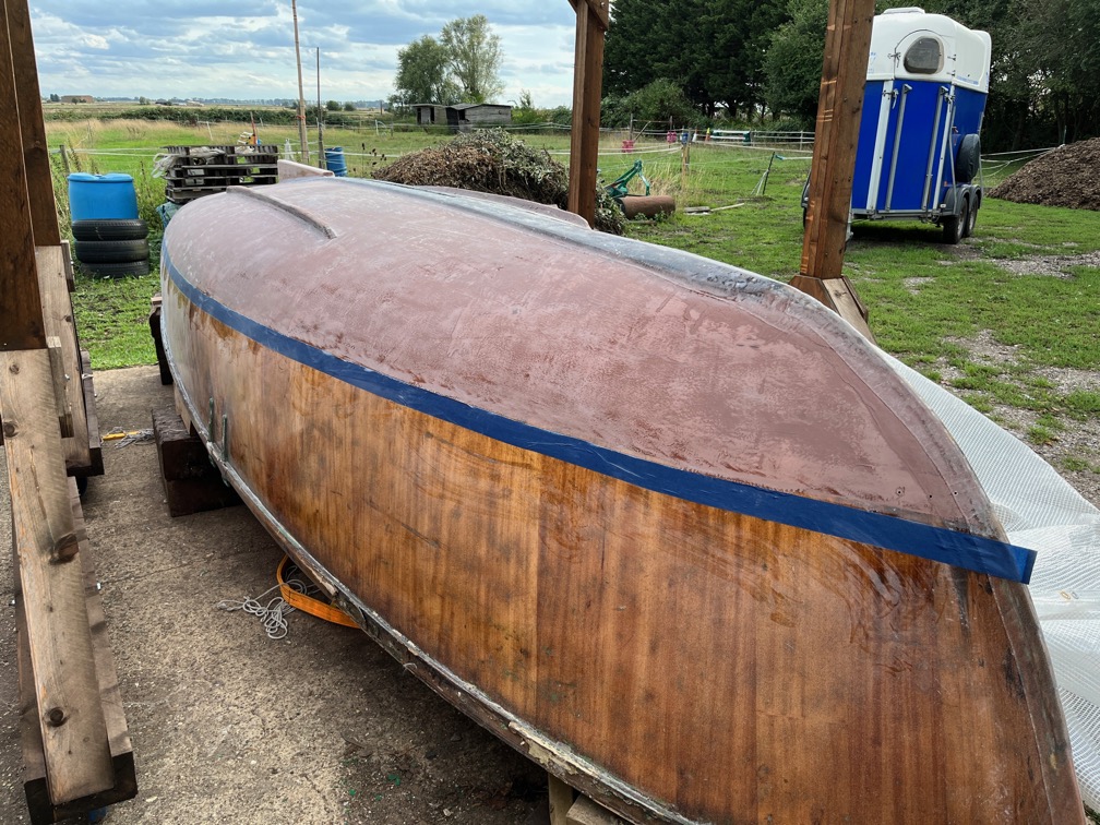
The forecast for today was in dry with a high of around 26º C, so I decided that today was the day the final copper epoxy would be applied to the hull. Firstly I went around the hull under the waterline and had another go at hand sanding the spots that I missed previously. The aim is for there to be no glossy, shiny bits. Impossible to do in practice, well it is for me, but I gave it a good go.
Then I mixed up 1.5 kg of the C-Guard Liquid Copper that I have used on Naiad previously and set to. This is a great product but it takes some getting used to since the first coat does not seem to cover particularly well. Hardly at all in fact. It even mentions this in the data sheet, but you should not go over and over the application trying to get a good coverage the first time. After about 15 minutes it looks a lot better.
The is the first coat about 30 minutes after application. As you can see, it looks quite good, but you can see through the coat in places. This is normal. You should also go round the hull with a brush and fill in the bits that the roller could not get to.
You could just do the whole thing with a brush, but that takes a long time, also meaning that you need to mix up small batches. The epoxy has a pot life of around an hour, but that is only just enough time with a roller. As it was I mixed up too much really and should have used two batches of 750g.
Still I did manage to get everything coated before the epoxy started to gel.
From a different angle with the sun shining on the hull from a different angle and hence the vastly different colour.
It was whilst I was having my cup of tea after cleaning up that I remembered the rudder stock. That has antifouling on the lower part, so that needed to be scraped away, sanded and then coated with copper epoxy.
I had done no work on this part of the stock at all, so scraped off the loose and flaky paint before realising that I needed to remove the gudgeon fitting. One of the six screws came out easily, the rest did not. Four of the remaining had been brass and one was stainless steel. I had to resort to drilling them out as none of those five could be removed using a screwdriver. Still, it all came apart eventually and I was able to sand off the remaining antifouling paint.
Since the fitting has to go back in the same place, I needed to plug the holes such that new screws could be put in to hold the fitting in place. I opened the holes out to 10mm and them plugged them with pieces of Ash arrow shafts that I have.
These are three of the recalcitrant screws and, as you can see they did not want to come out easily at all.
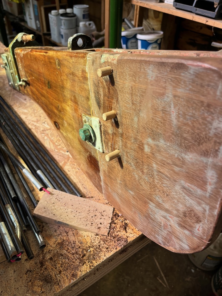
This is how the rudder stock looks right now with three wooden plugs being glued in on one side…
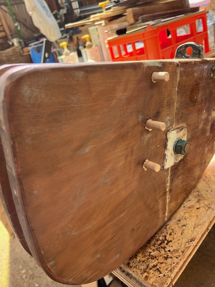
…and three on the other.
I’ll give these plugs about an hour to set, cut them off flush with the stock and then coat them with the copper epoxy.
Time for a cup of tea.
Actually, whilst I drink my tea I need to mention something about the C-Guard Liquid Copper product. When I first purchased this stuff back in 2018, it came in a pack that contained the resin, hardeners, copper powder, plastic gloves mixing sticks, stainless steel scrubbing pad and instructions. You can’t get it like this right now as the price of copper powder varies pretty much from day to day. But the very kind Gentleman that runs the company, Tony Grimes, will sell you everything else and leave you to source the copper powder. He even suggested where to get it at the best price.
This was ideal for me since I had nearly 3 kg of copper powder already and this meant that I did not end up with a whole lot more and was able to purchase just the extra that I needed.
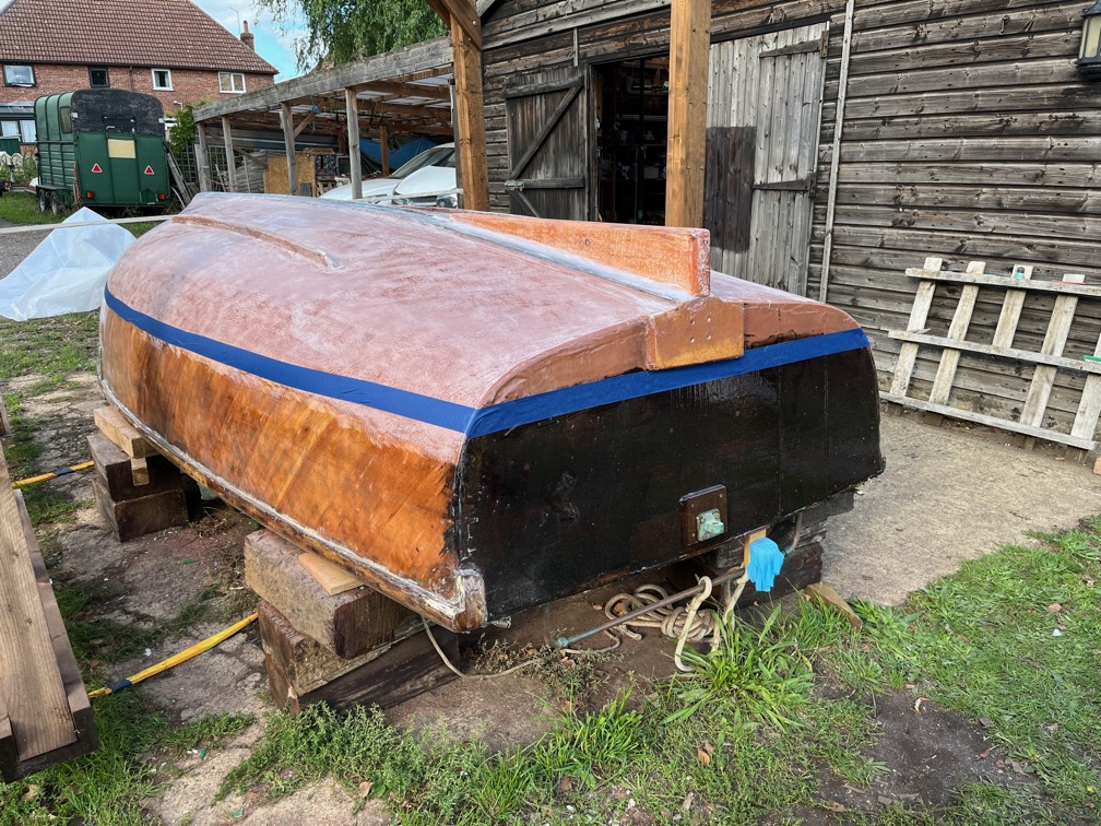
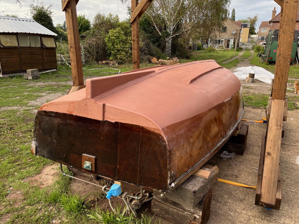
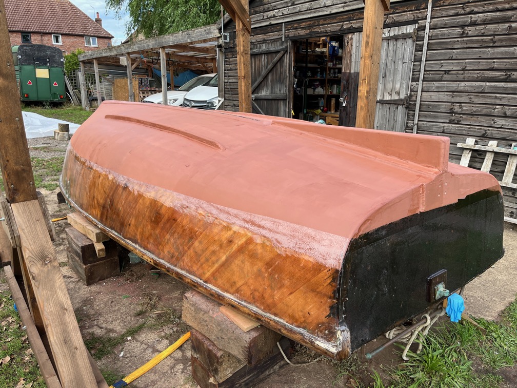
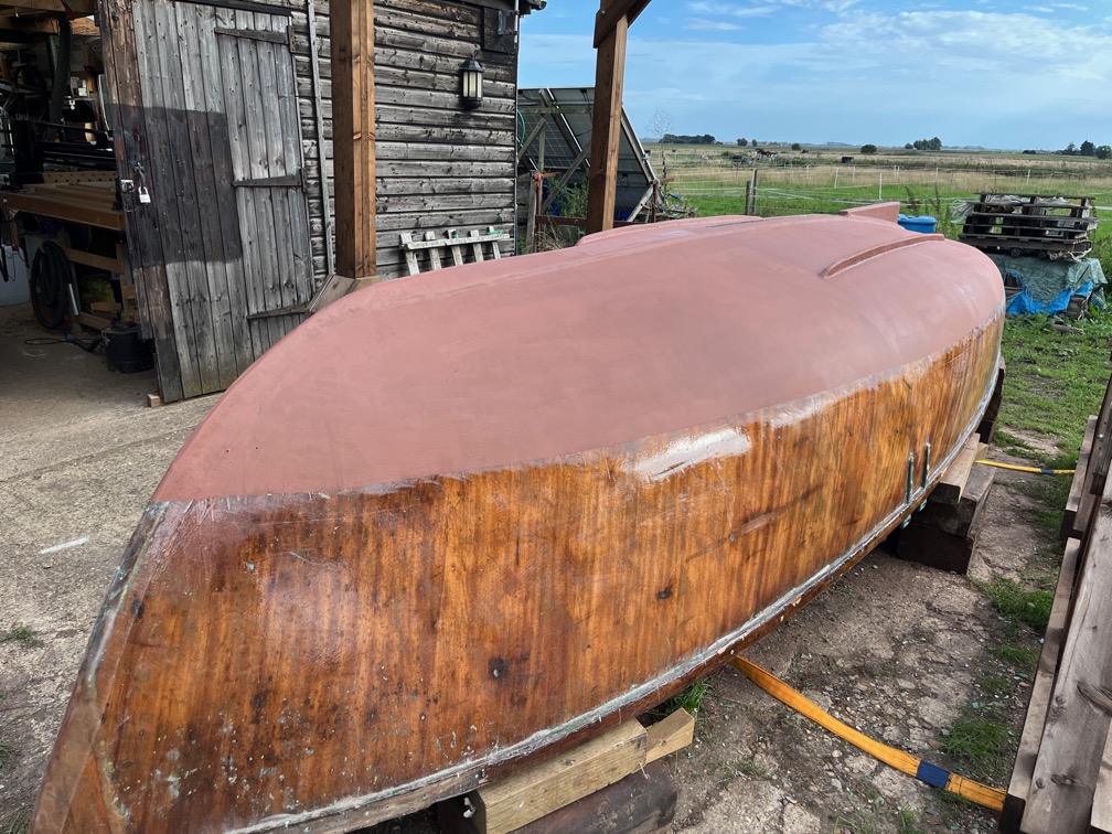
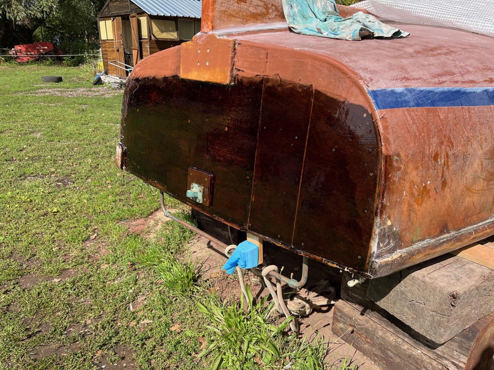
Here is the second and last coat and with the masking tape removed.
It doesn’t stay this colour. Once this has hardened properly, at least 24 hours, then you use the stainless steel scouring pad to remove the very top layer of the epoxy exposing the copper to the air and, eventually, the water. At this point it goes green.
I’m not finished with the underside of the hull yet, there’s the keel band to put in place and I also need to do some tidying up in the keel slot which will have to wait until I have the boat on its side so that I can access the slot.
However, I have the last of the major epoxy work done.
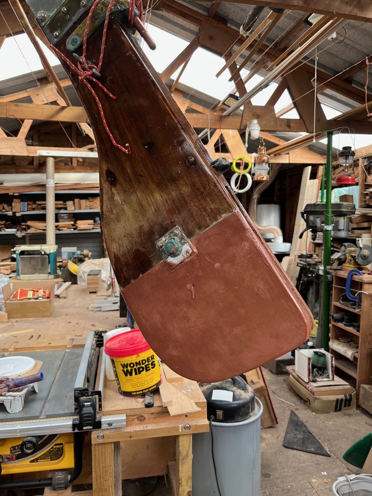
The rudder stock also has two coats, so once that has hardened i can complete the remaining work on that.
I am not a fan of sanding, never have been but I realise that it is a necessary part of making just about anything in wood. This is a common sentiment amongst makers although I do know one or two who quite enjoy it.
Before the hull is turned back up the right way, I have to sand the hull under the waterline and complete the copper epoxy work.
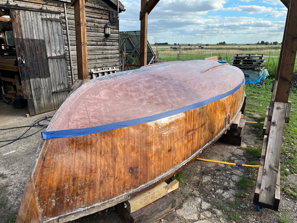
I won’t bore you with the details, suffice it to say that this is not a difficult or time consuming task as this is just to provide a key for the next coat. So, lightly sanding is the requirement, not removal of material. Mind you there were one or two places that needed to be sanded away a little harder, but on the whole this one side took two or three hours to get to the stage you see here. Sanded, swept, air blasted and wiped with a cloth soaked in Acetone. I will need to go over a few spots where the epoxy is still shiny by hand but I’ll do that after I’ve sanded the other side.
Next task, the transom.
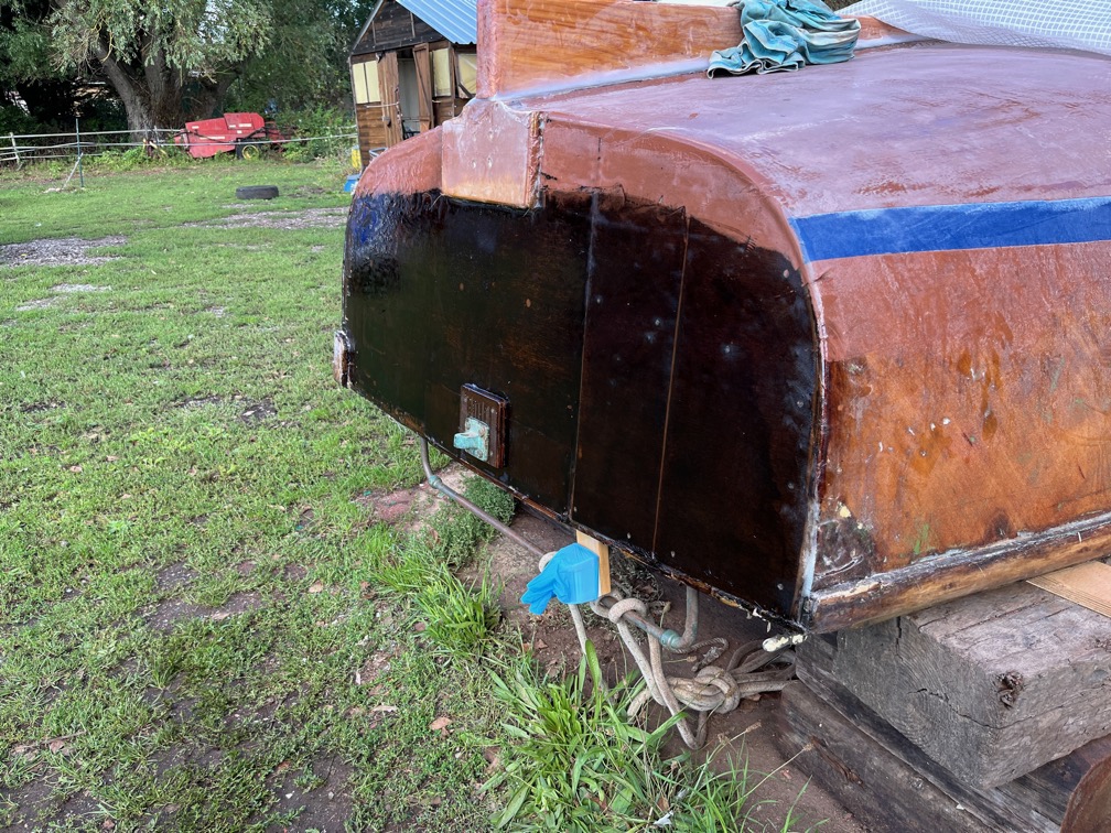
Sanded, coated with neat epoxy, fibreglass laid on and then coated with epoxy. I didn’t get the sanding quite right on the far side, the copper epoxy will protrude above the white boot top, but I’m not going to try and fix what is a cosmetic error now.
Second coat, applied with a brush and not a roller so that I don’t need to mix up as much epoxy. Although the rollers are only 4″ long, they really soak up a lot of epoxy which is then wasted.
Note the rubber glove over the stern navigation light to stop drops of epoxy dripping on it !!
Time for a cup of tea.
Having taken a break I started sanding the second side of the hull and was surprised to find that it took around half the time for the first side. Not sure why.
I marked the location of the upper edge of the boot top and then taped it.
This was carried around the transom.
The remainder of the touching up sanding I’ll do tomorrow and then decided whether or not to add the final two copper epoxy coats to the underwater hull or wait until next weekend.