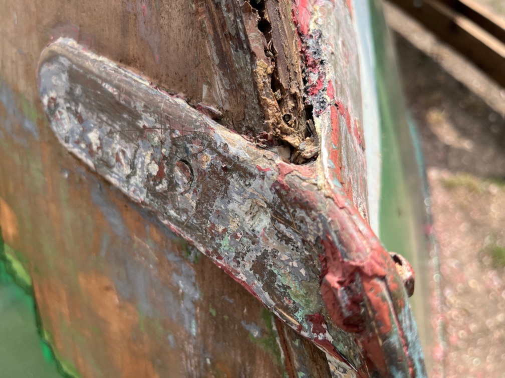
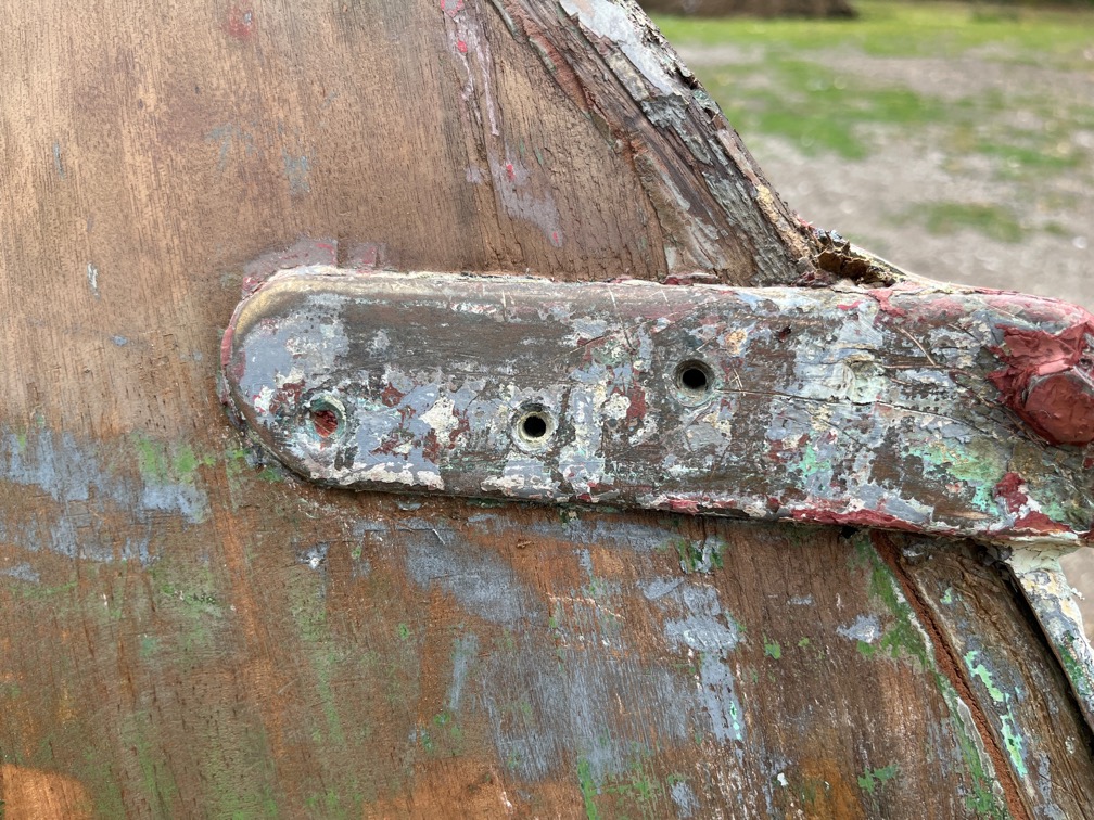
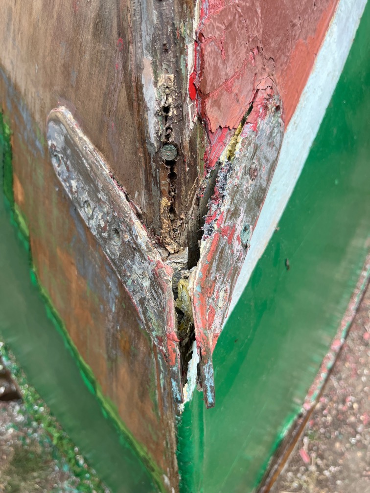
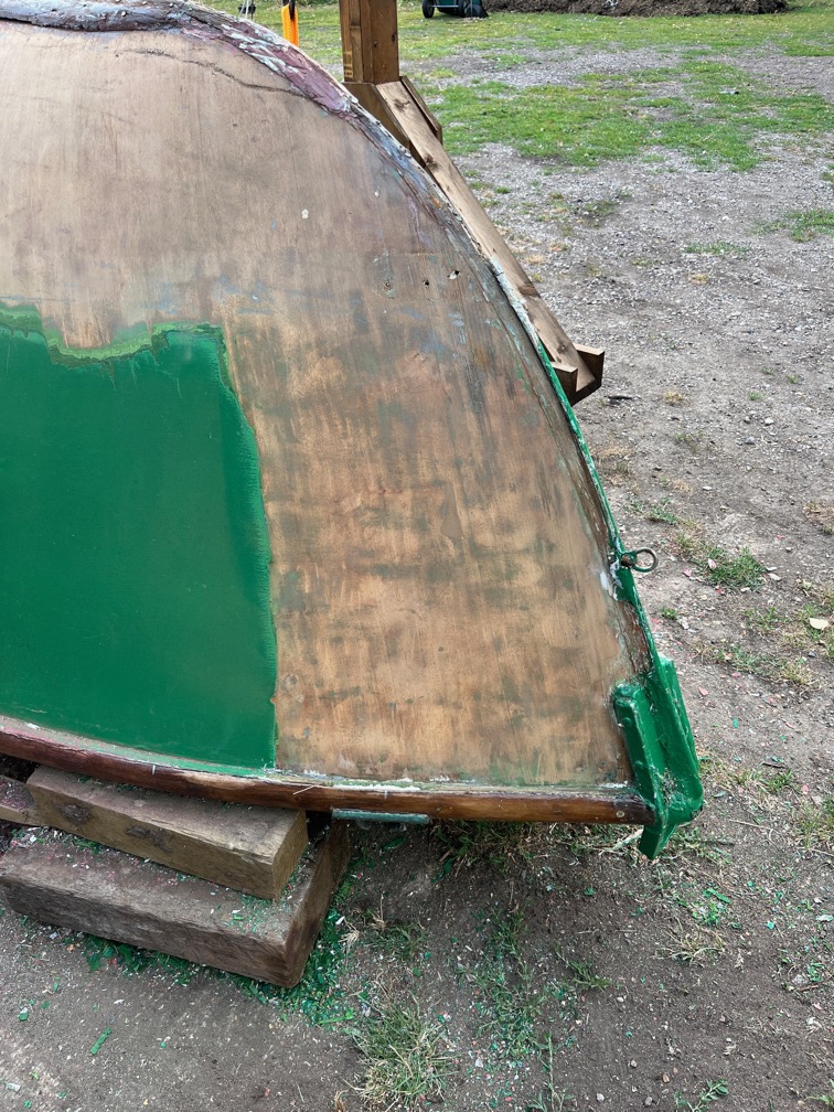
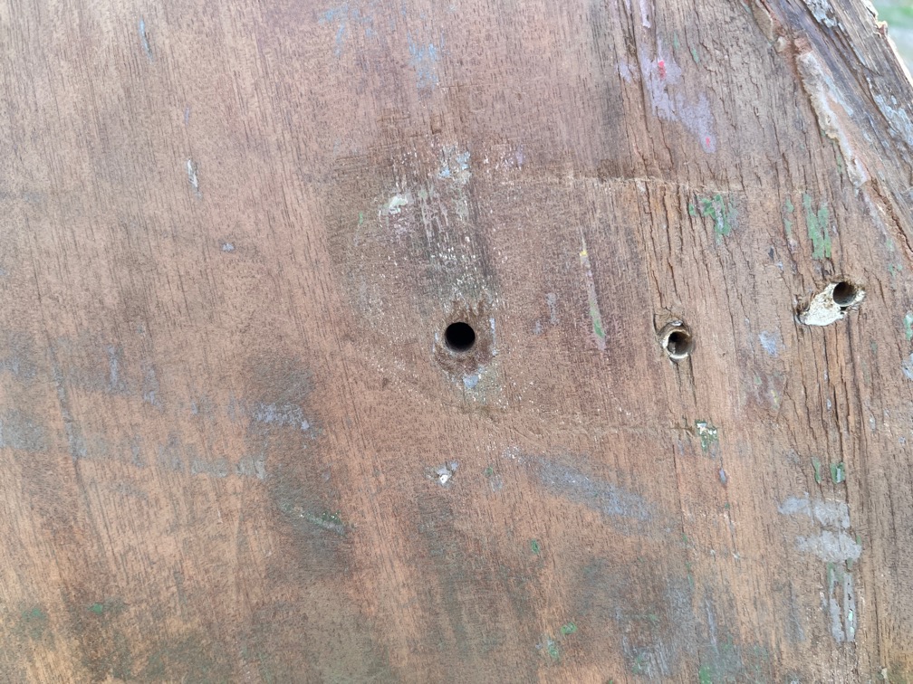
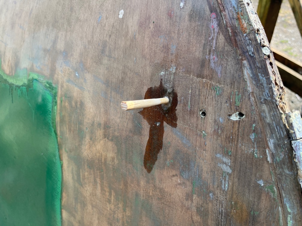
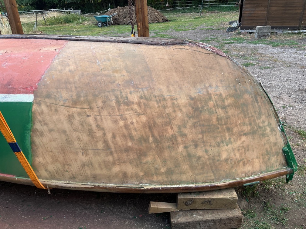
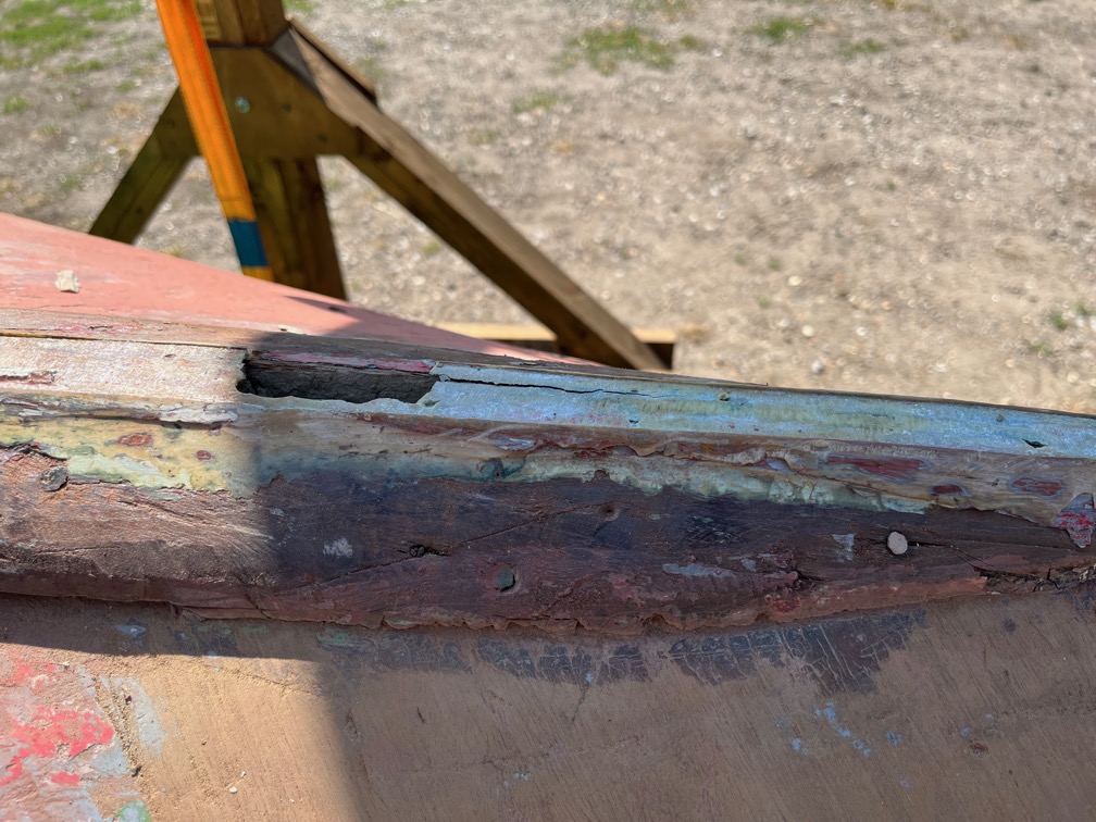
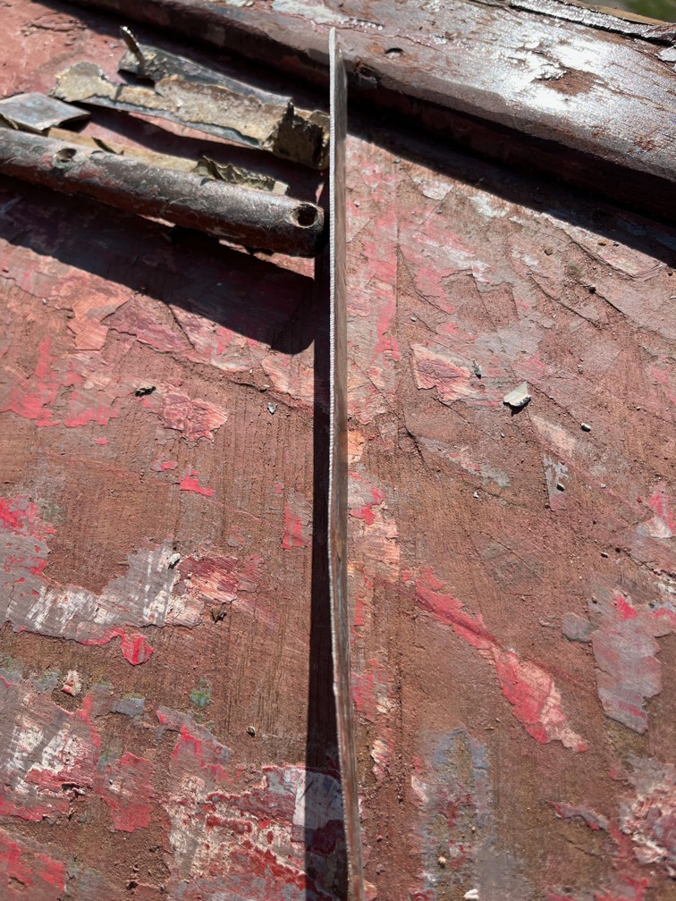
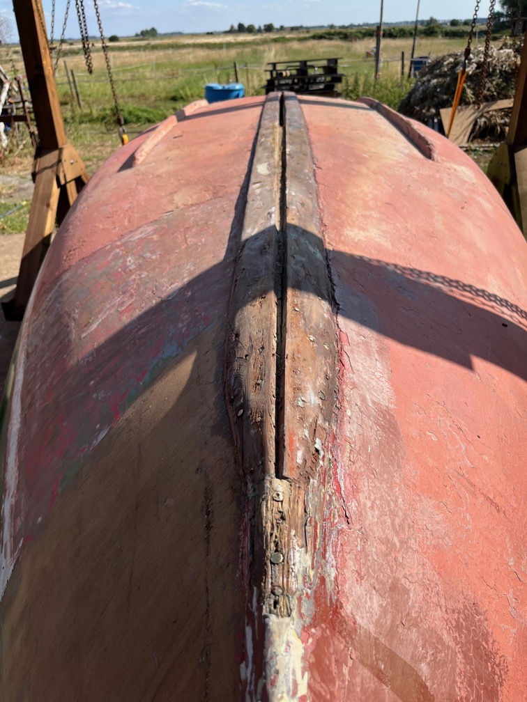
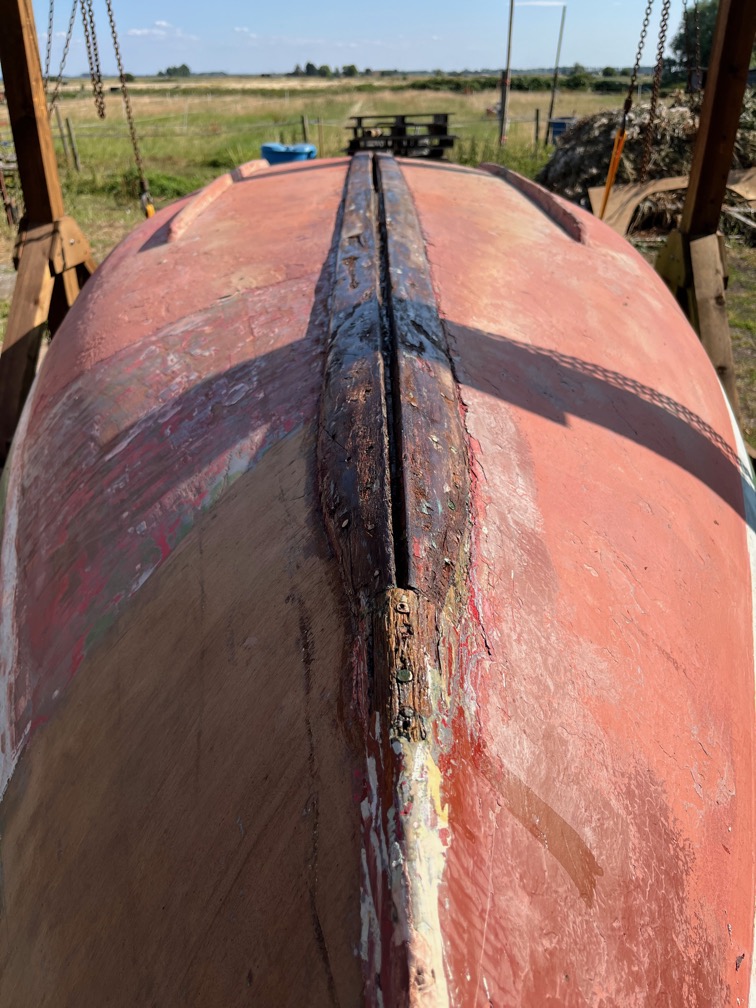
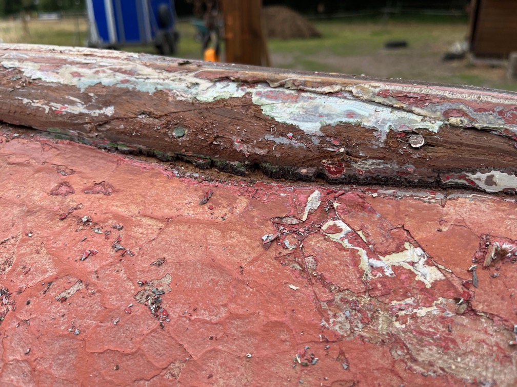
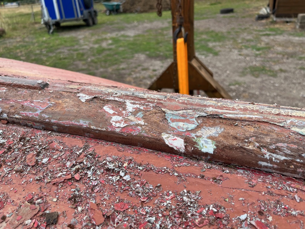
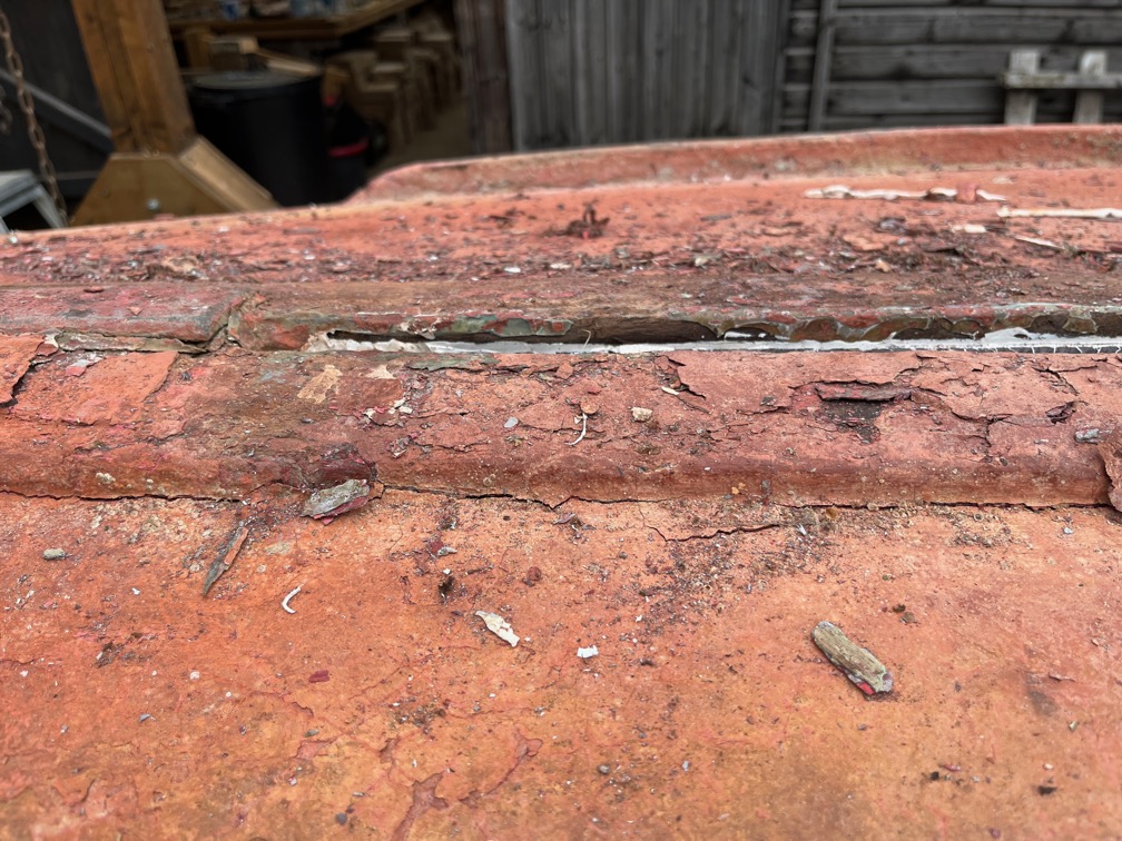
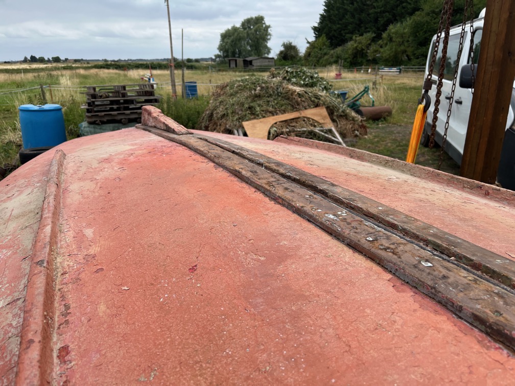
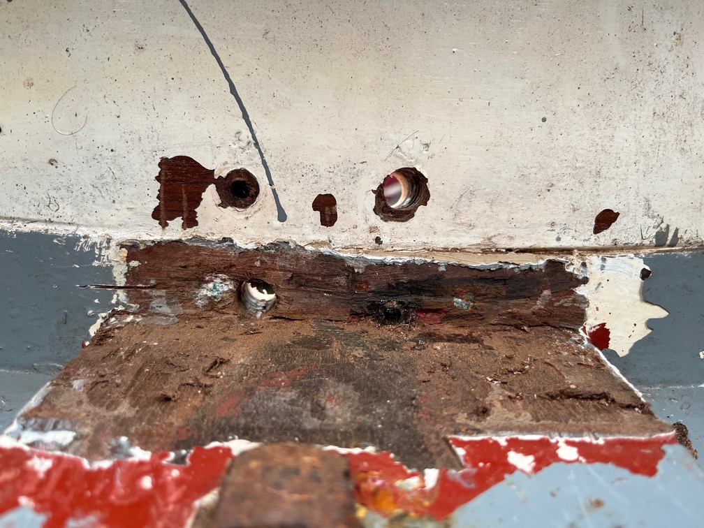
As I approached the aft end of the hull with the hot air gun and scraper, I decided to take a look at the gap the surveyor noticed between the hull and the transom.
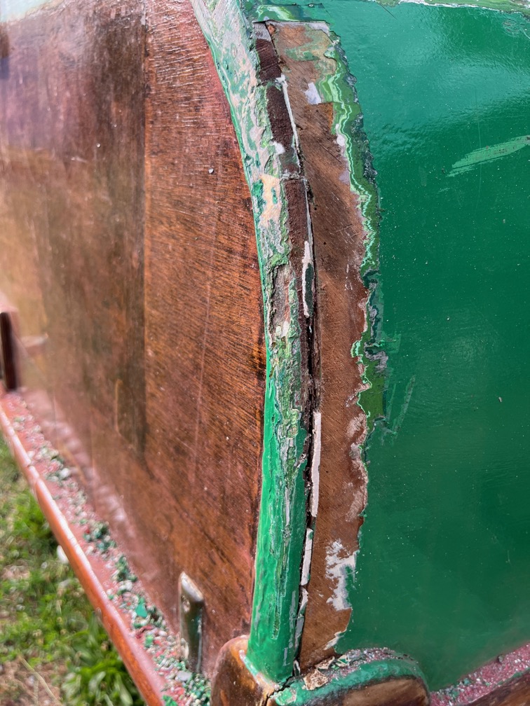
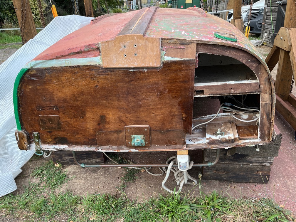
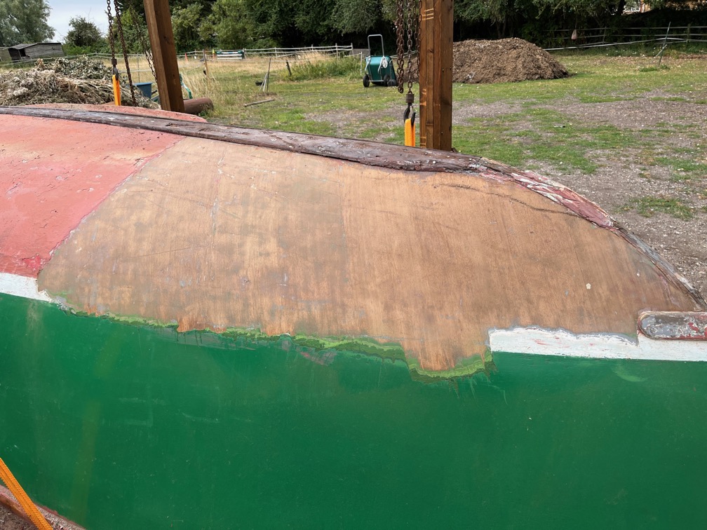
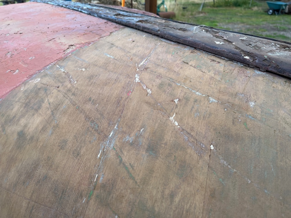
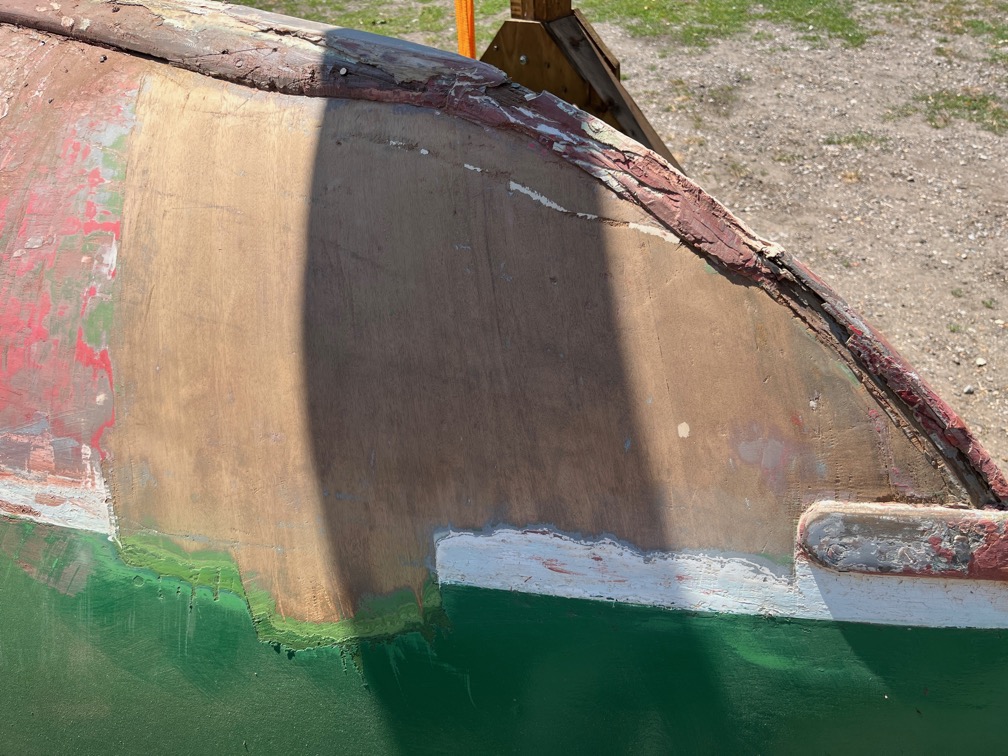
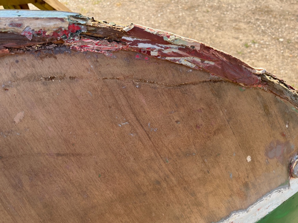
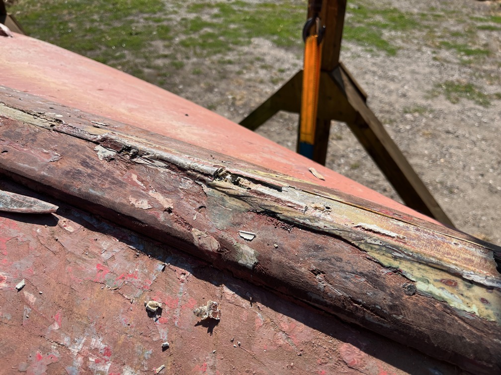
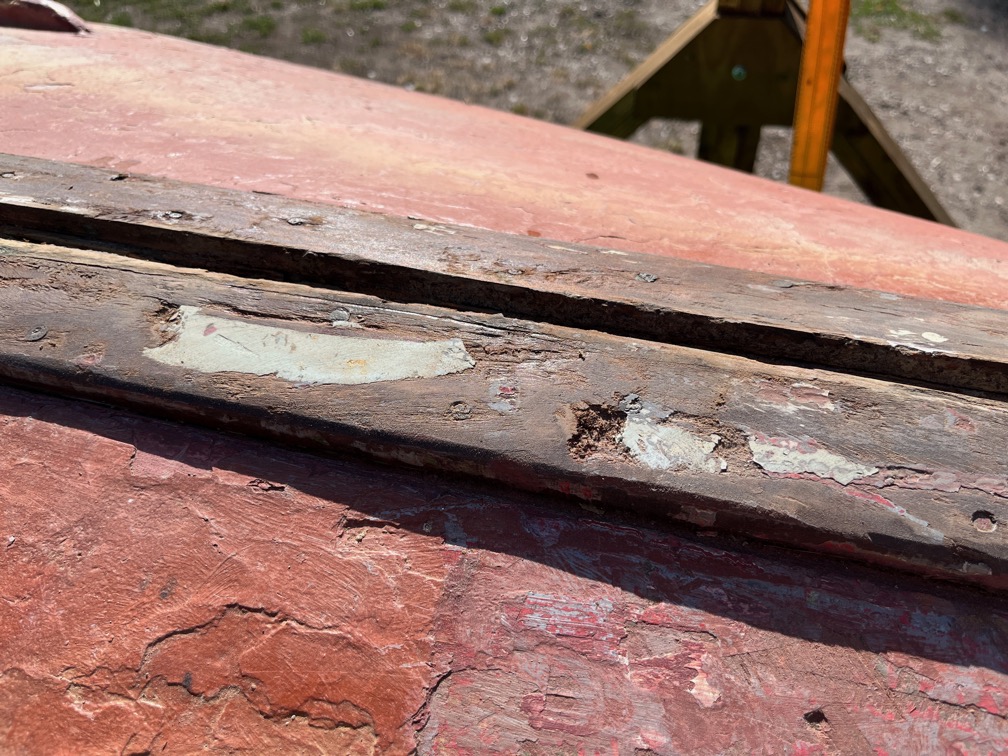
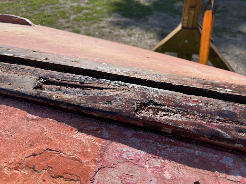
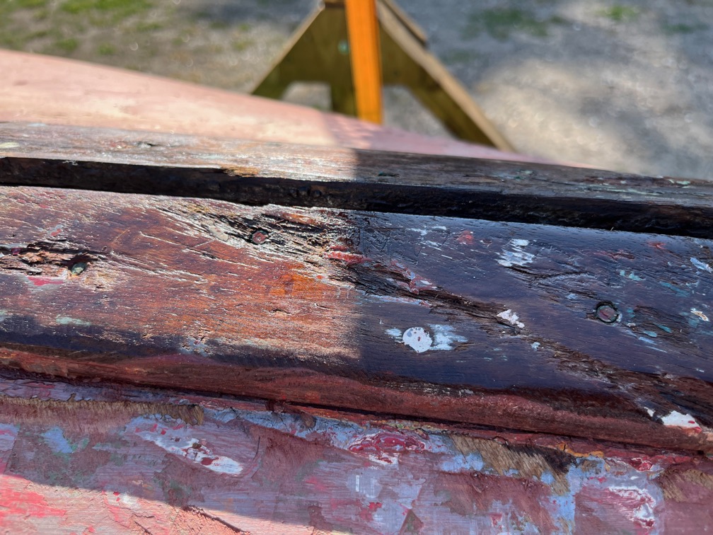
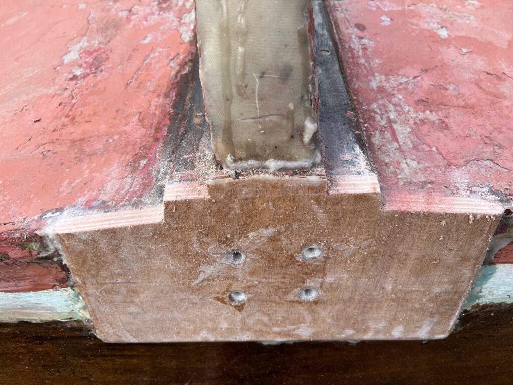
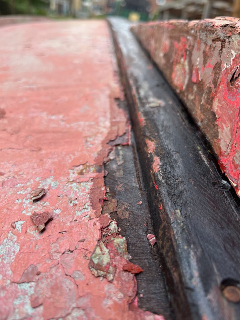
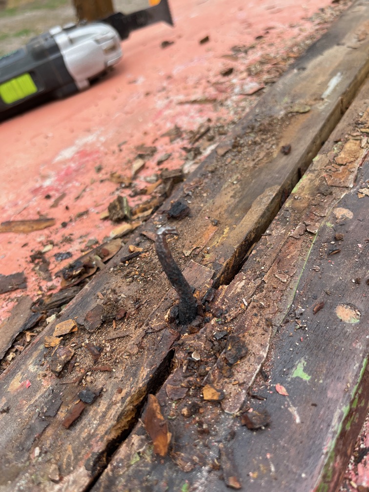
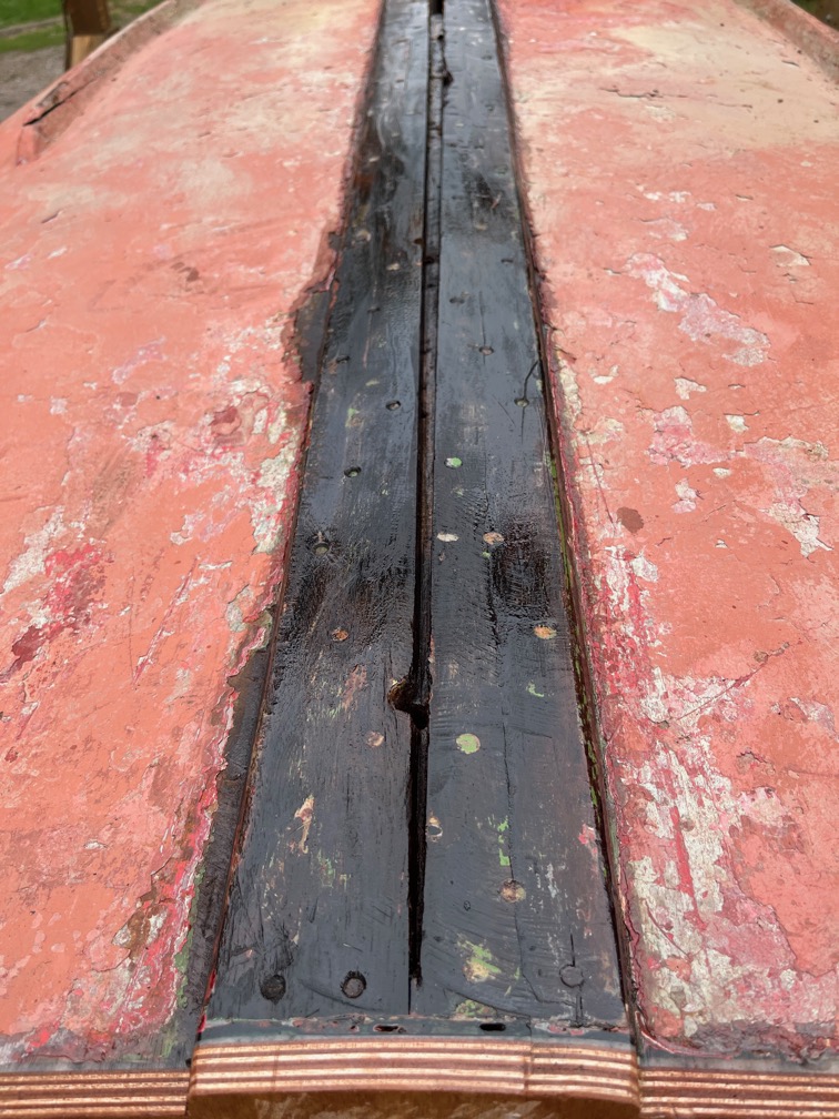
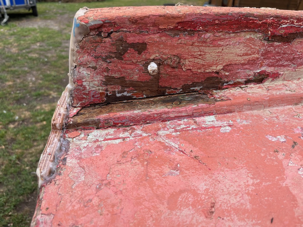
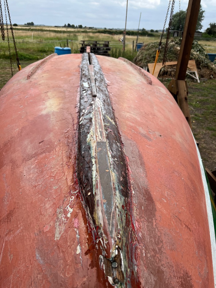
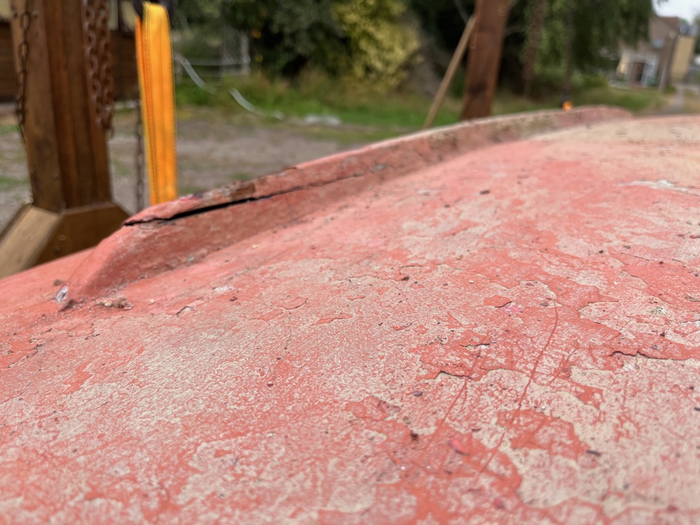
I removed the antifouling and topside paint at the very end of the hull a portion of which you can see here. The curved piece, still painted green, is an end capping put on the the edge of the transom to protect the end of the hull. As you can see, there is a gap which has been filled and which is falling out.
The surveyor thought that this gap might be the fastenings though the hull and into the transom not holding because of the soft transom, but this hull never used fastenings and was glued instead.
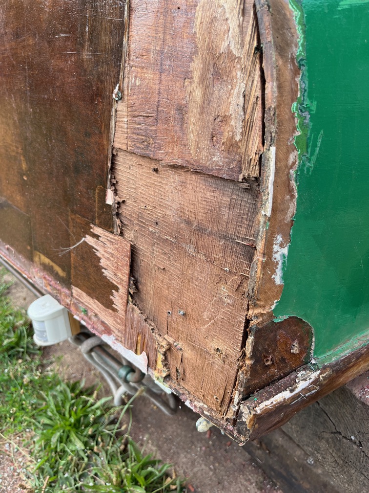
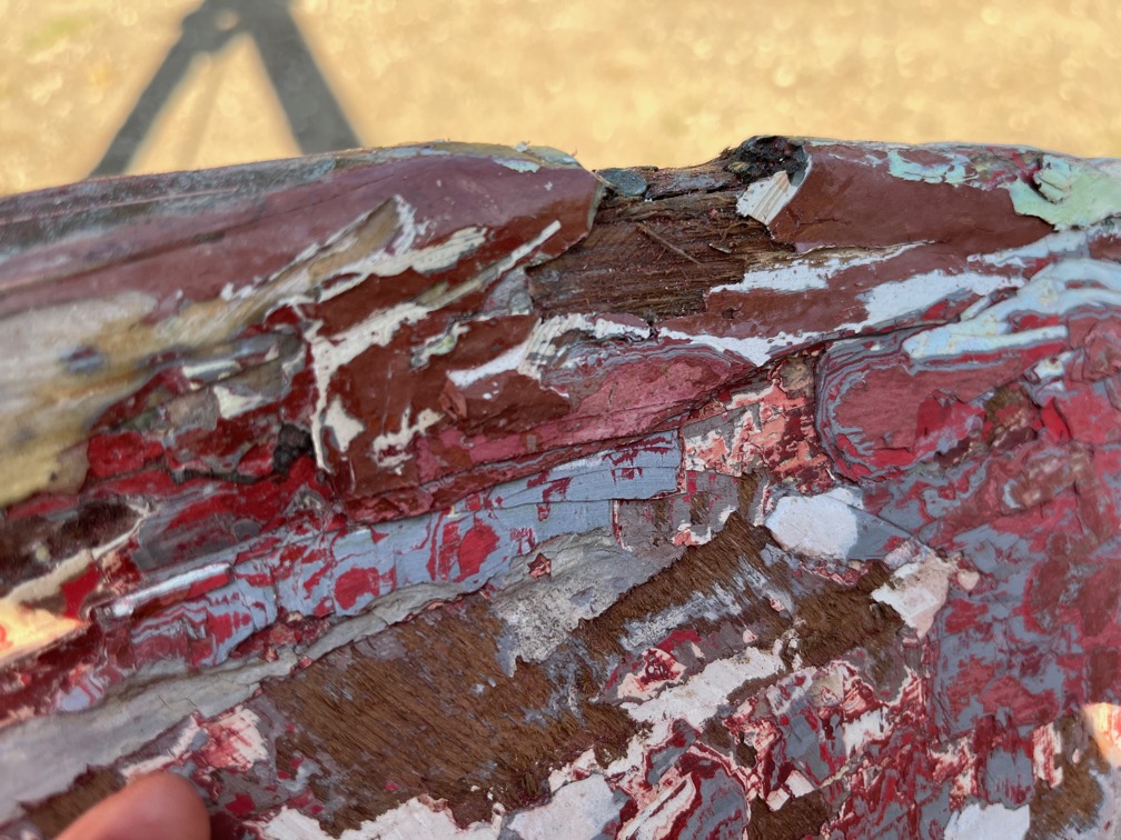
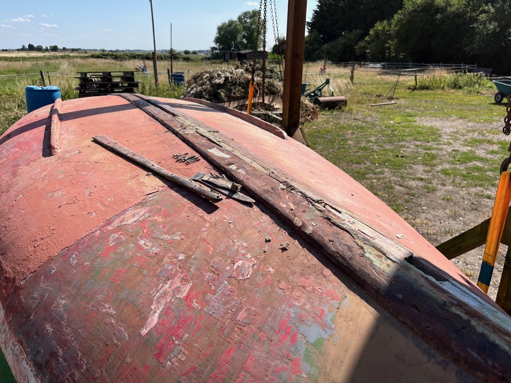
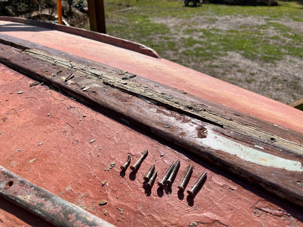
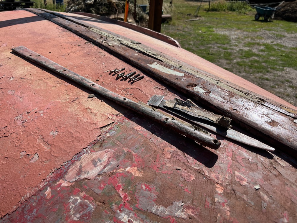
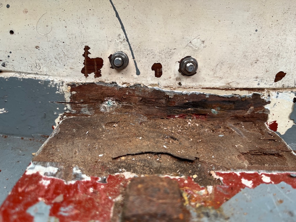
I pulled the capping piece off and part of the transom came off as well. This was obviously the soft area that the surveyor mentioned in his report.
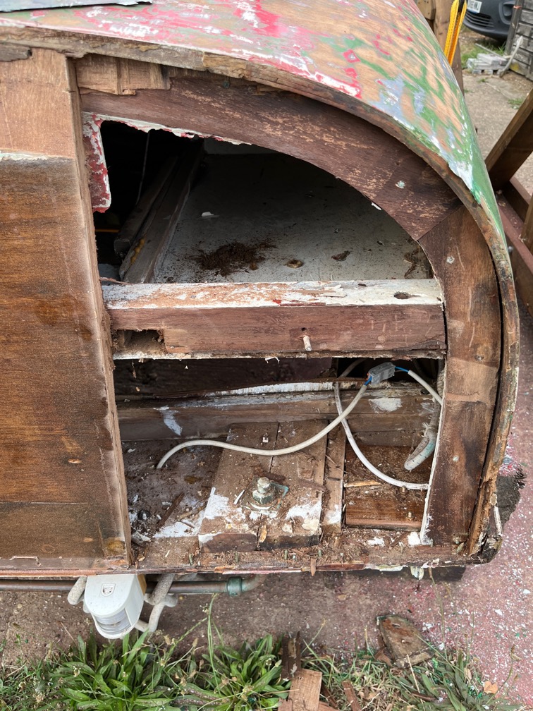
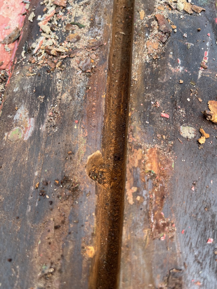
I set to with the multitool, chisel and hammer and soon had the transom cut away to reveal good wood. Looks quite dramatic, doesn’t it, but it is not a difficult repair. The hardest part is going to be fitting the new laminated piece in place since the hull curves inwards. Still, the first thing to do is to make a template to fit the widest part and laminate up a piece to fit in the space. I will probably step the edge of the remaining transom to make the fitting and glueing easier.
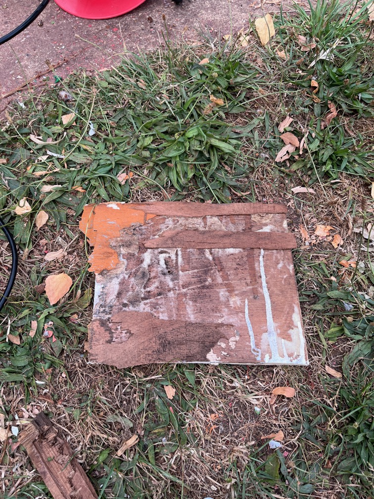
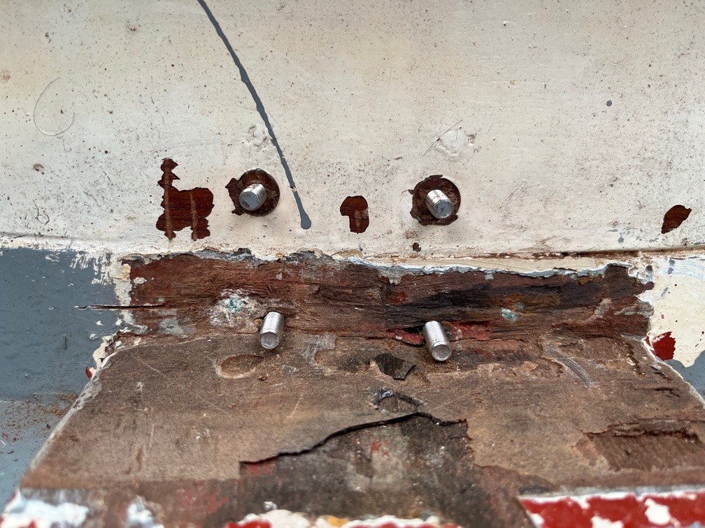
Sometime in the past a primitive repair had been carried out by glueing this piece of plywood to the inside of the transom. Completely ineffective.
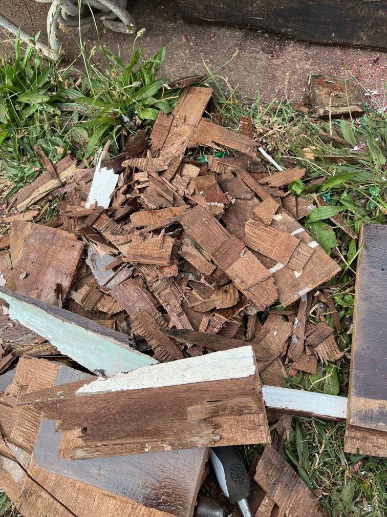
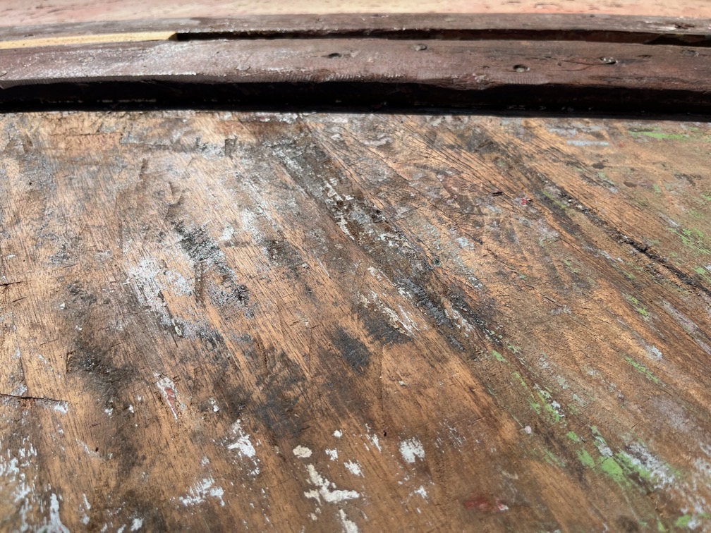
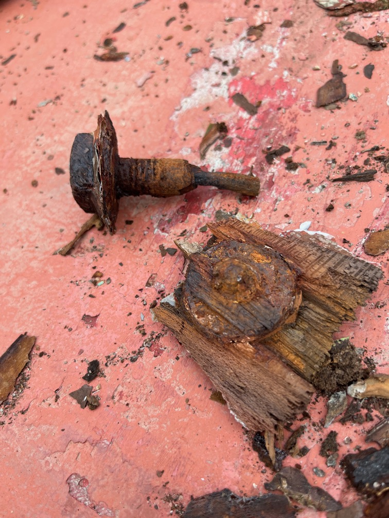
This is all that remains of the transom, it came out in flakes. No wonder the surveyor noticed “soft returns” when tapping this area of the transom.
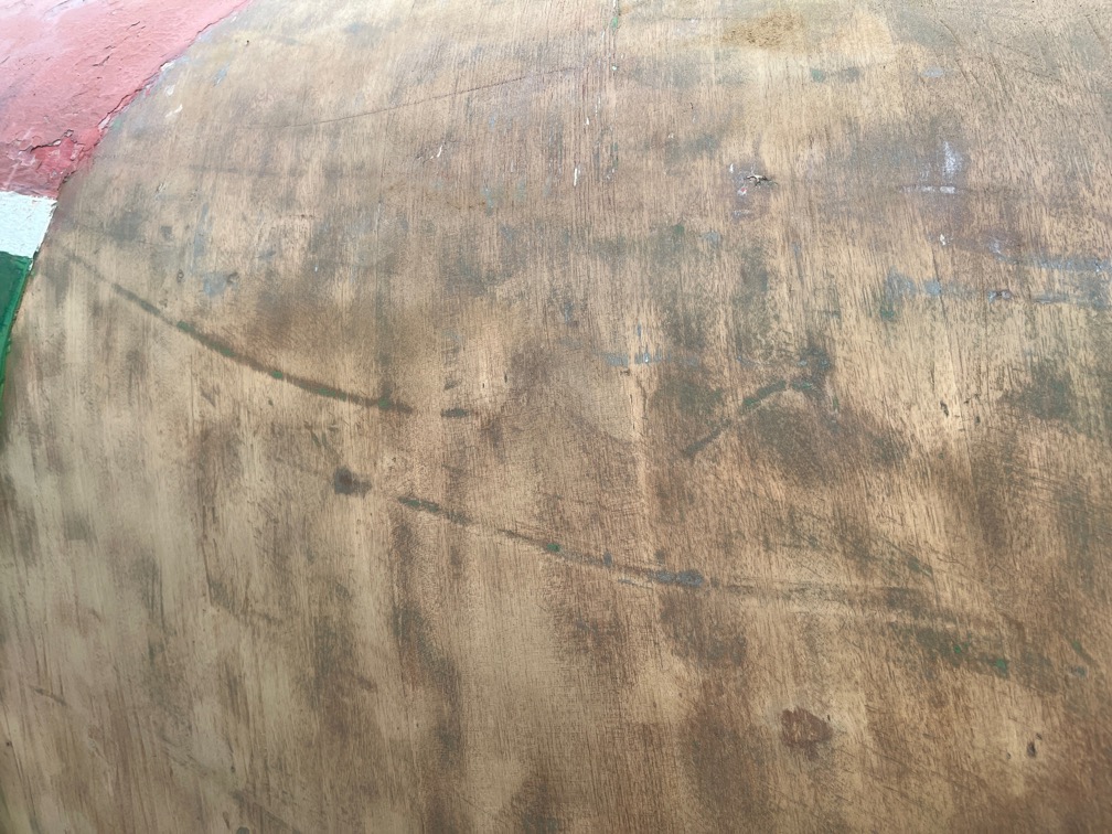
I had said in my last post that there were a lot of scratches under the antifouling but that “None of the damage is deep, no more than a millimeter”.
I have to say that I was wrong about that.
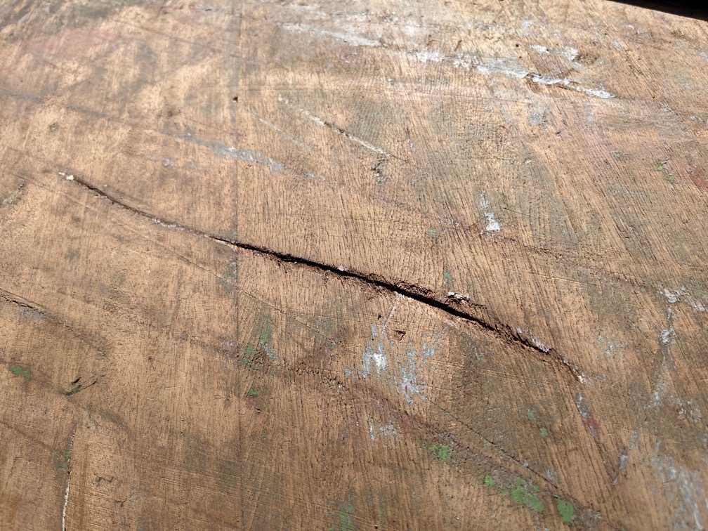
This one, is nearly 5mm deep and since the hull is only 10mm thick, this once can be considered to be significant. This is one of the scratches photographed before, but after I had removed the filler.
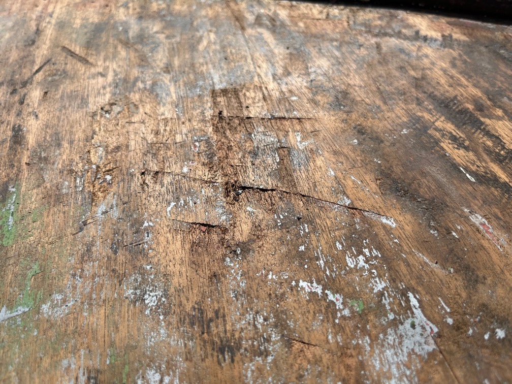
These are not quite so deep but deeper that I had expected.
There is also patches of a black substance that looks like tar, but the paint has stuck to it, so I expect that it is not tar or bitumen. I’ve tried using various solvents, except Acetone as I don’t have any, and nothing shifts it. This patch here is after being sanded as well as the solvent tests.
I laos tried to use the belt sander on the hull but the surface is too uneven to allow it to work properly, so I went back to the orbital sander.
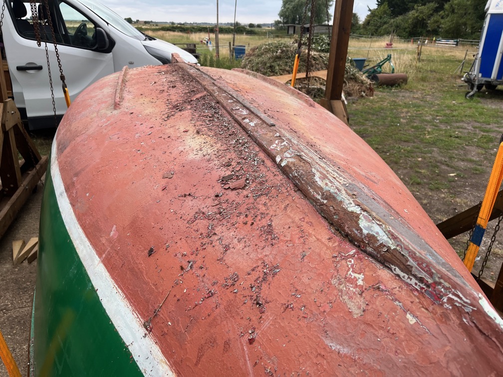
This is the progress to date. nThe section of antifouling between the bilge runner and the keel has been removed and I think that this is probably the hardest part of the job. Trying to scrape away the paint at a stretch is not easy on the muscles and I think that when I start the other side, I shall do this bit first.
Scraping progress has been slow this last week as I have been on my own for a week and that means looking after the horse. That in itself isn’t s problem except that the time I had been spending in the cool of the morning between getting up and starting work was now taken up with feeding duties and pooh picking. Frankly, most days it was too hot to do any significant scraping in the afternoon after work, hence the slow progress.
However, that all changes tomorrow and I will be able to get back to scraping first thing and progress should improve,
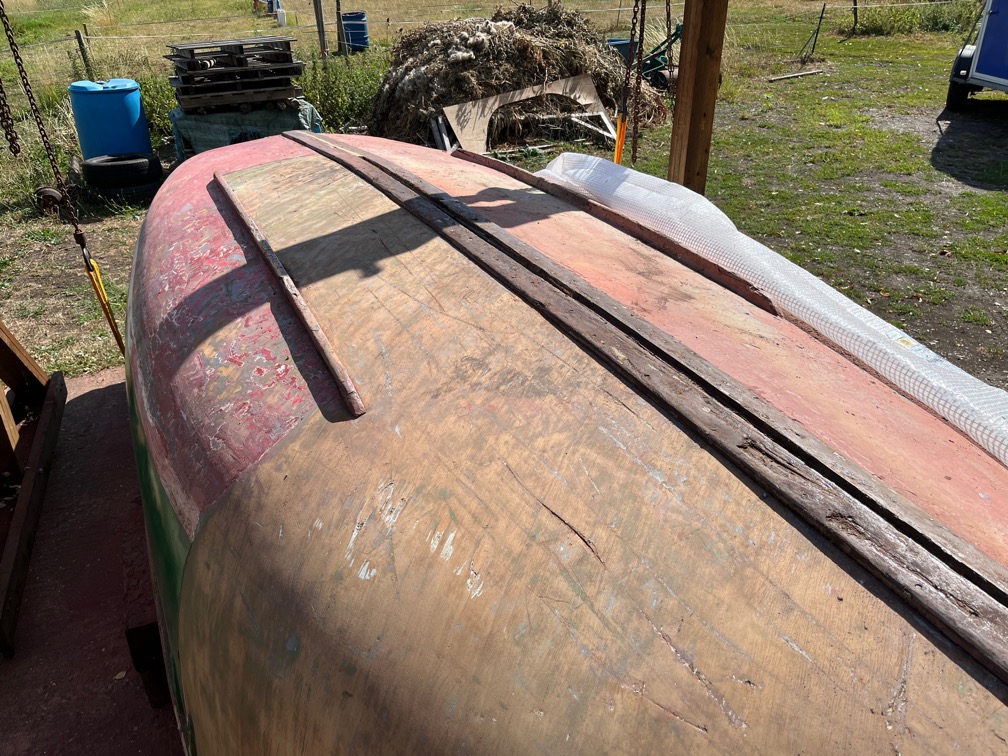
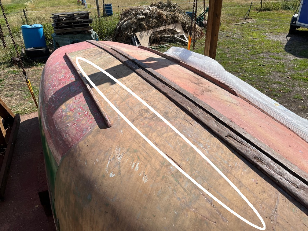
Now that I have quite a lot of the wood under the waterline exposed, I can see that some of the scraped line up. The one highlighted above shows one such line.
Although the main task is to remove the antifouling and topside paint, there are a few other tasks that need to be done and I decided to use these to break up the paint stripping work which is quite physically, and therefore mentally, demanding.
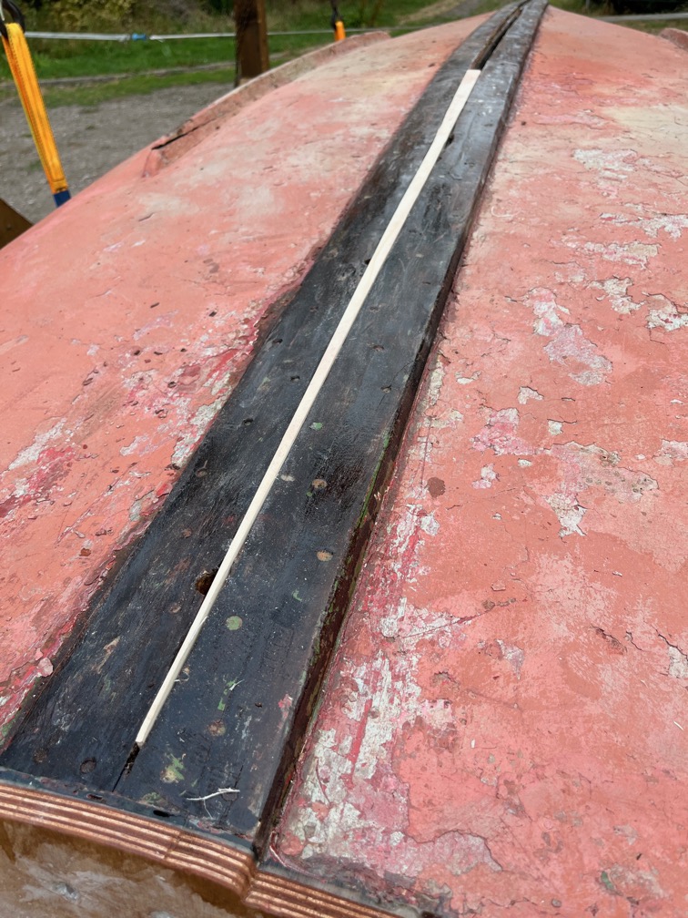
So, I started on filling the aft part of the slot between the reinforcing timbers and the holes through the keel and hog.
And this is the first piece. Looks good, but takes a while to make since not only does it taper in width…
…it tapers from top to bottom as well.
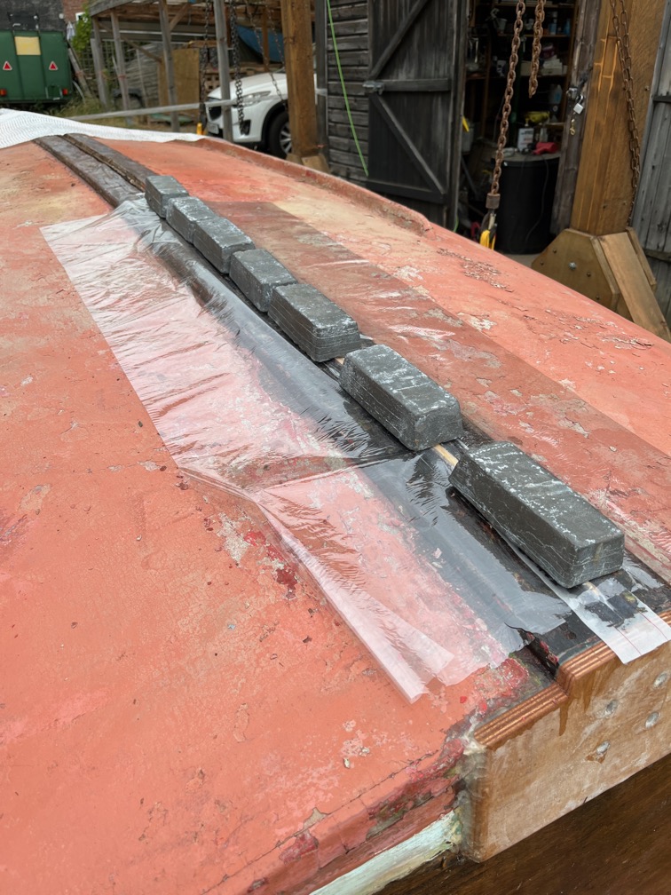
I used some slightly thickened epoxy to glue the spline into the slot and used lead weights to bend it into the slight curve. The plastic film is to prevent the epoxy sticking to the lead.
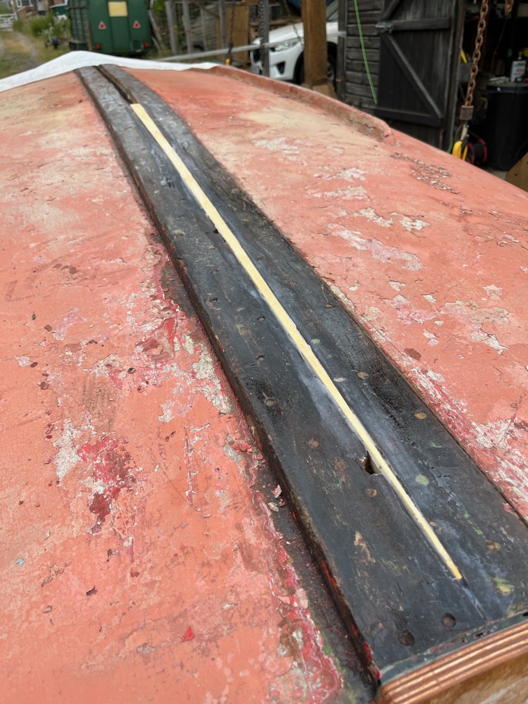
The result is fairly good. I had made the spline a little too tall for the slot so that I can cut it down to the correct height as the depth of the slot is not consistent.
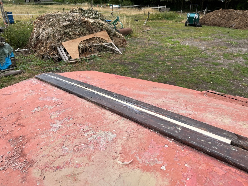
Here the spline has been planed down to the correct height and it is ready for the next phase which will be carried out later.
The scraping work continues albeit slowly due to the heat.
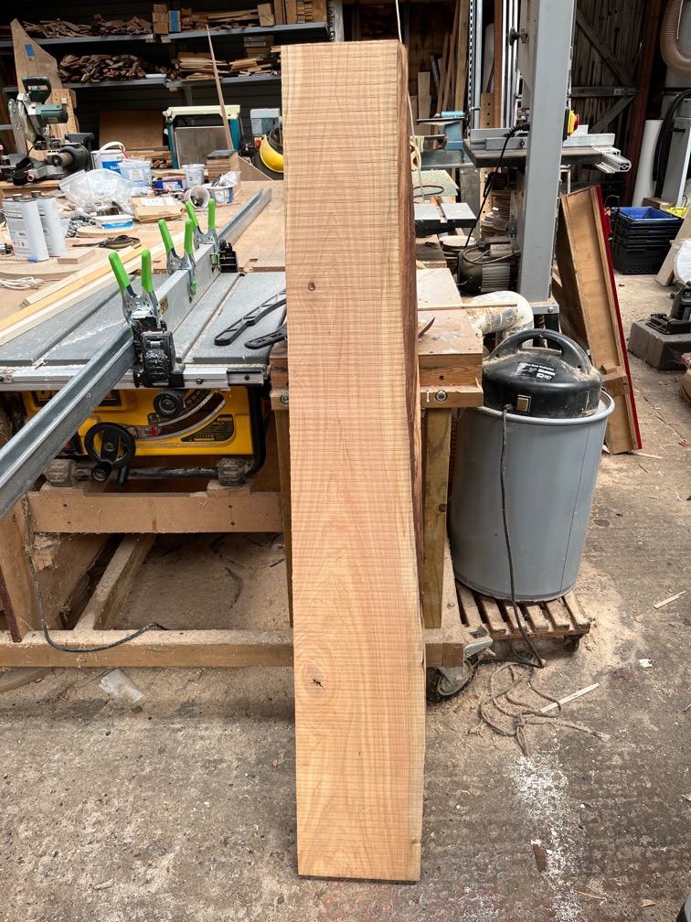
The cedar plank arrived in the post during the week from which I will fashion a new skeg.
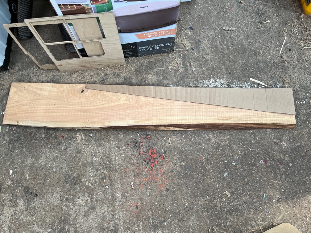
But firstly I cut out a cardboard template to make sure that I can get two pieces out of the plank. As you can see, not only can I do that but I can avoid the knot in the plank as well.
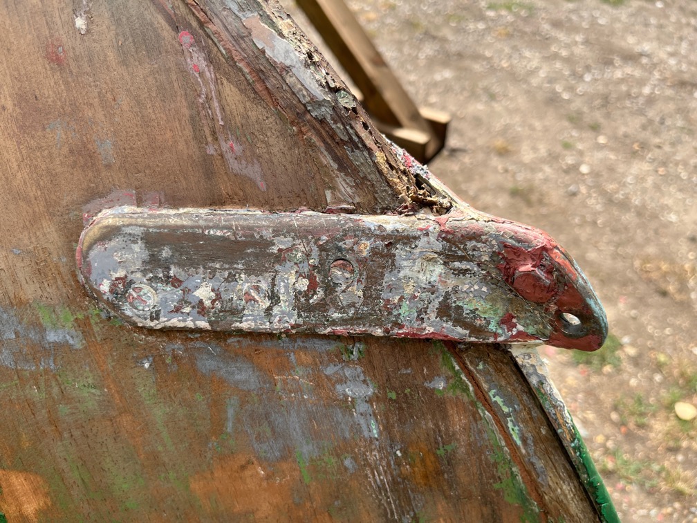
The wooden stem of the boat is not in very good condition once the keel band was removed and will need to be strengthened before a new band in put in place. This meant that I needed to remove the bobstay, technically the lower bobstay chainplate. Conveniently this is made in two pieces.
I say conveniently because of the six screws (brass of course) holding the fitting to the hull, three came out easily, two turned but did not come out and one broke off.
The leftmost screw shown here is the one that broke off.
Still, with the bolt holding the two parts together removed, the individual plates came away easily. Oddly, the bolt was stainless steel, not brass.
With the chainplate removed it was easy to clean up the area as you can see.
I used my nifty 6.3mm screw-removing tool to take out the degraded brass screw…
Then glued in an Ash dowel. The excess glue was removed with a wet cloth. Once the glue was dry I cut the plug flush with the hull using a pull saw.
Then it was back to work with the hot air gun and scraper.
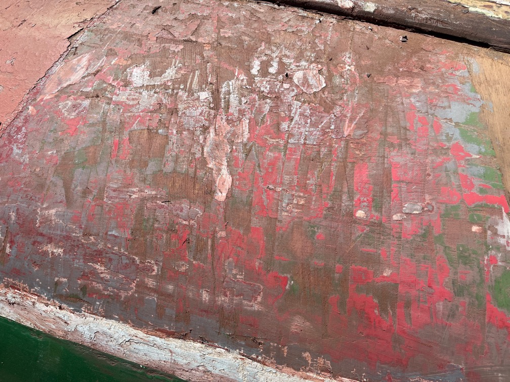
It is quite apparent that neither of the two previous owners worried too much about bumps and scrapes, they simply filled in the dings with filler and painted it over. None of the damage is deep, no more than a millimeter for these scratches, but there are a lot.
Here is a closer look at some of the scrapes on the sides.
And some on the bottom of the hull nearer the keel.
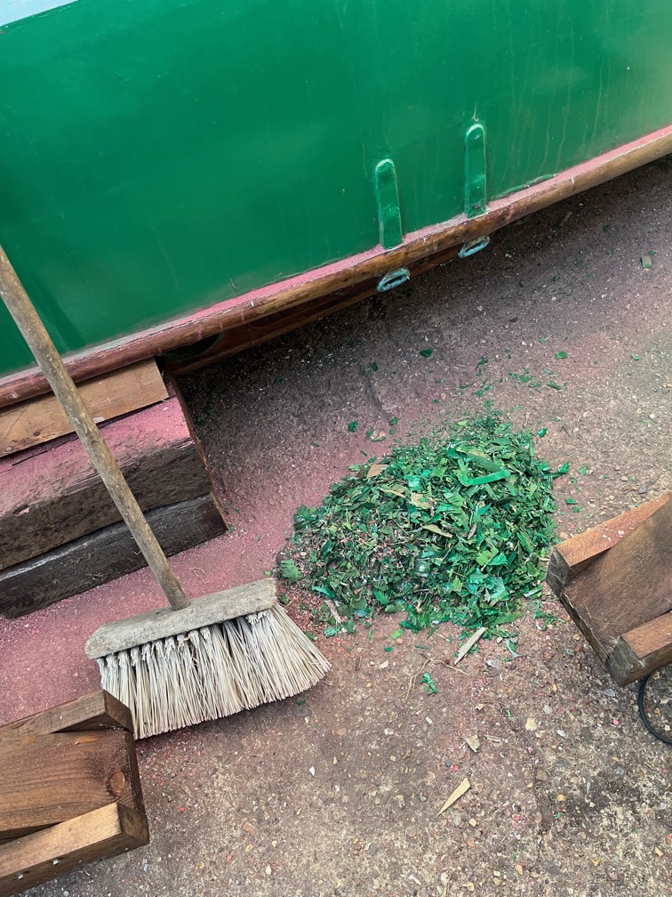
I am under regular scrutiny by a neighbour who sits outside his house in the sun and can see me working, so I make sure to be seen to sweep up the scrapings and then putting them in a stout bin bag.
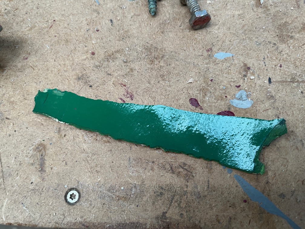
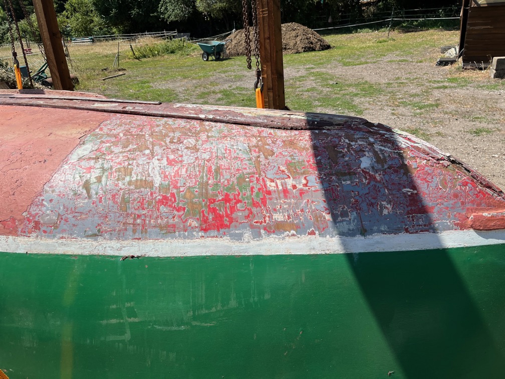
I don’t know how many coats of topside paint there are on the boat, but I can easily see four different shades of green and which looks like an undercoat.
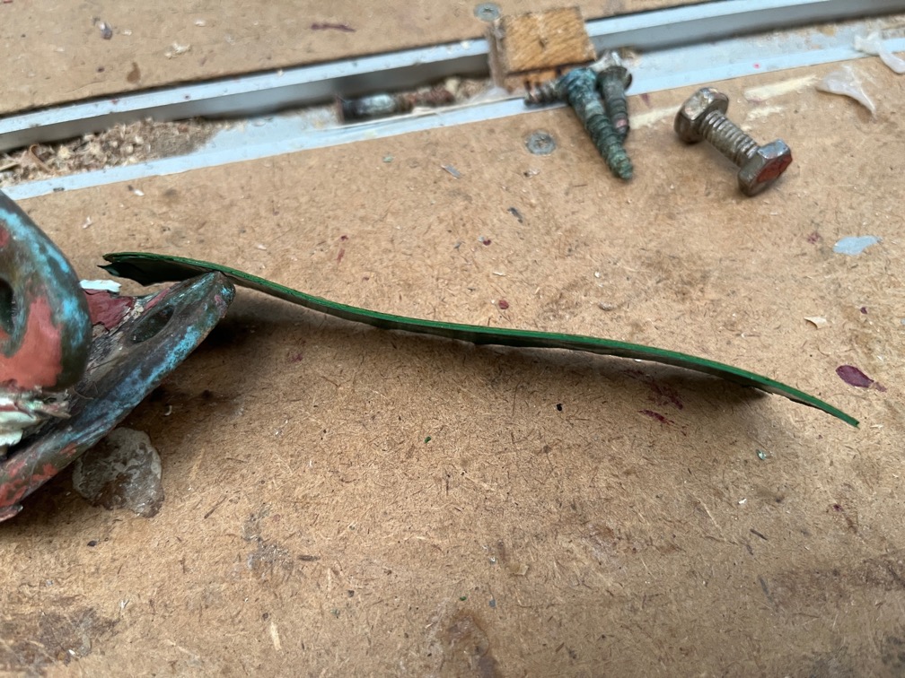
As a result some of the scrapings that come off in one piece right down to the wood are quite thick.
This one is 1mm or 1/16″ thick.
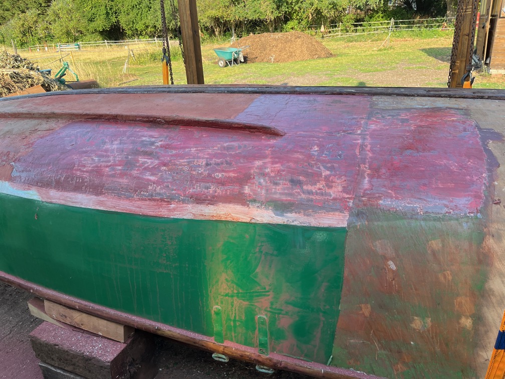
Removing the antifouling is very hard work, so I decided to slop a load of the stripper on the paint and leave it overnight to see if it made the removal task any easier.
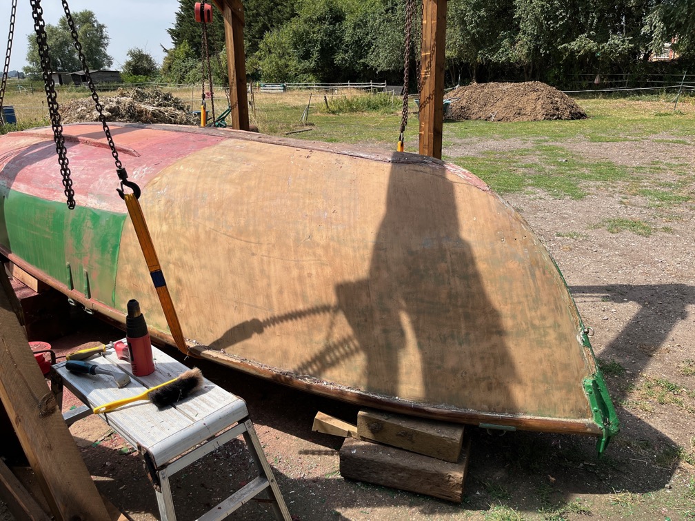
Progress here is about a third of the way down the side. Progress, but slowly.
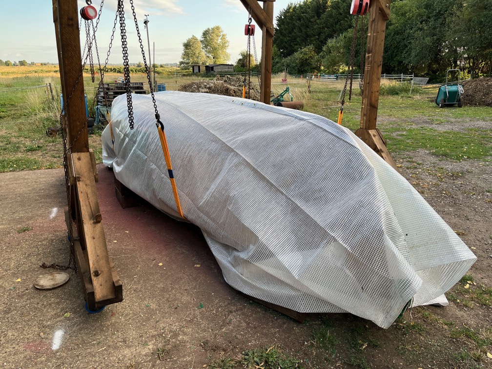
The forecast for one morning was for light rain, so I used a plastic tarpaulin to keep Shoal Waters dry. No stripping for today. To wet, then too hot and then because I had too many other non-boat tasks to do around the property.
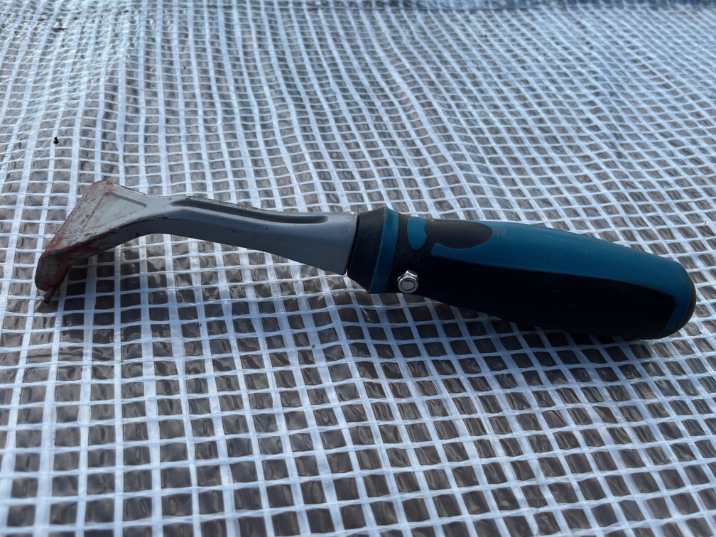
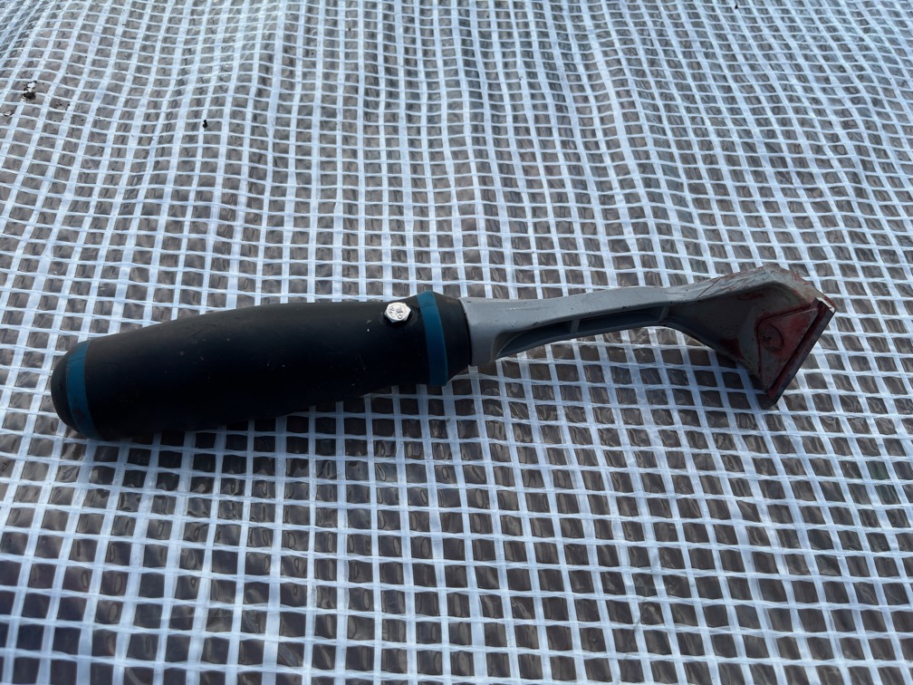
I also broke the scraper. Well, not broken exactly, but the heat of the sun and the heat of the hot air gun softened the plastic handle enough that the metal scraper section came out, even under light scraping.
As you can see, I have “mended” it with a bolt. Not sure if that will work. If not, then I’ll have to try and buy a new one.
I decided that it would be prudent to try to find the best method of removing the antifouling (AF), and in this case “best” meant fastest that left the hull in good shape. A secondary concern was to leave me in good shape as well, so anything requiring too much physical effort was discarded.
Getting old is the pits (GOITP)!
I started with my best paint scraper and removed as much of the loose AF as possible.
As you can see, the results were mixed. In some places the AF came off right down to the wood with ease, in others it was very resistant to being scraped off. I found that the best way to carry out the scraping was to move the tool along the grain of the underlying wood which prevented the sort of damage to the wood that scraping crosswise made.
I then applied a liberal coating of the AF stripper, left it for the ten minutes as instructed…
… and then scrapped it off.
The result was less than impressive. However, the instructions did say that heavy build up might required more than one application.
In this section of the hull I can count at least 12 layers of AF and barrier paint, so the chemical stripper is not looking that effective in this case.
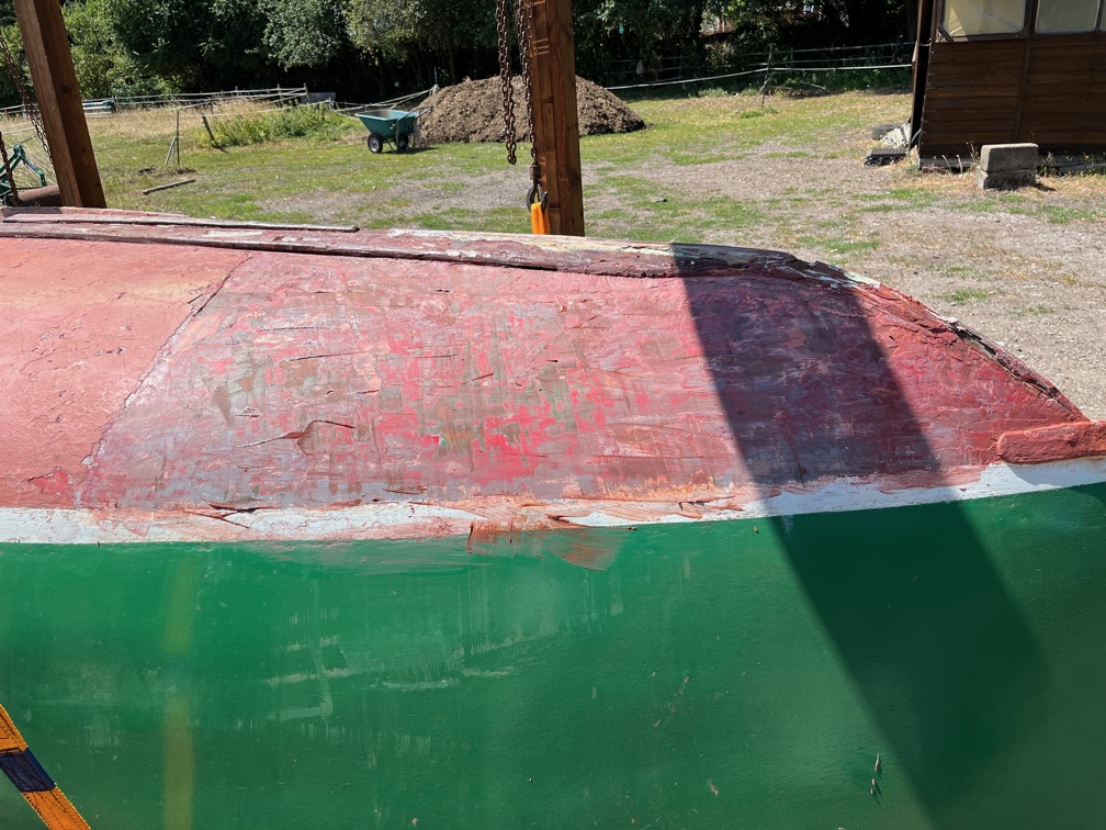
This is the result obtains using the scrapper, a hot air gun and then a light sanding. This is a good way to remove the AF and it works well on the hull paint and boot top as you can see.
There seems to be a scrape in the hull that has been filled and I expect that there will be more dings and scratches found as more of the bare hull is revealed. This one looks like an unexpected encounter with a rock.
This is the scratch with the filled removed. I’ll fill this and any other such damage, with thickened epoxy before the fibreglass cloth is applied.
Having decided on the best AF removal method, I turned my attention to the keel band, the bronze protection strip on the keel. This came off fairly easily as it is not screwed into the wood but mostly into the filler between the two reinforcing timbers.
In places the filler is a soft mastic like material and in others it is something like polyester resin.
It looks quite messy in places but I think it will clean up fairly well.
The plan is to remove the filler and apply penetrating epoxy and then return to the scraping which I estimate will be the better part of a week to effect, depending on how well I hold up physically, GOITP !
The keel band seems to be made up of several different pieces. There’s this huge chuck that looks original.
There’s another section that is of the same sort of width as the big piece but is very thin.
And there are several other pieces that are the half-round cross section that you find on older wooden dinghies. The large piece will probably be put back but the others will almost certainly be replaced with a stainless steel flat bar,
Time for a cup of tea.
It didn’t take long to clear out the gap between the timbers and give it a light sand.
There were more damaged spots in the timbers that were filled with something that looks a lot like car body filler, but it came out easily enough.
These two were quite deep…
… as were some others. Once the majority of the filler had been removed I put on a liberal coat of penetrating expoy.
Interestingly, the epoxy has highlighted two areas of damage, seen in the shadowed area, where the damage is more or less in the same place.
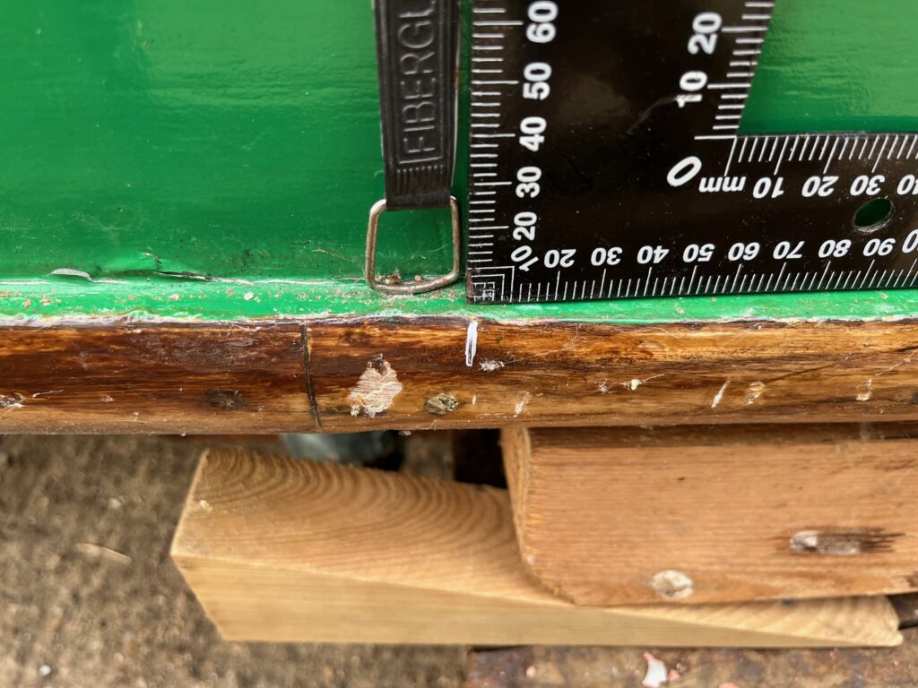
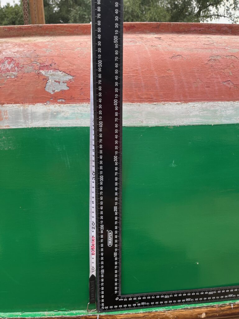
The next task in the long list of tasks for the rest of the year was to measure the height of the boot top from the gunwale. I marked a number of spots 300mm apart on the gunwale and measured up from these marks to the boot top, noting them down on a piece of paper I must make sure not to lose.
I use a large square and a soft tape to make the meaurements up from the white marks.
The measurements were not exact but then do not need to be.
I decided to trim the backing pad on the transom next, a quick job with a pull saw..
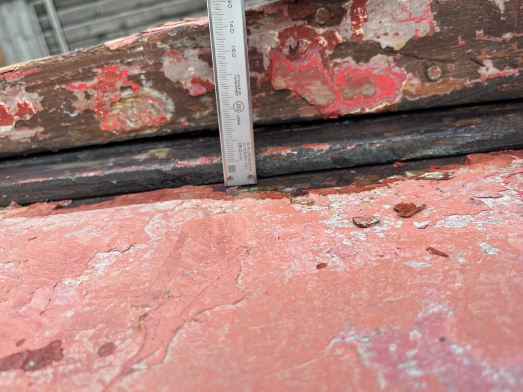
I noticed whilst cutting the backing pad that the antifouling paint is many layers and quite thick.
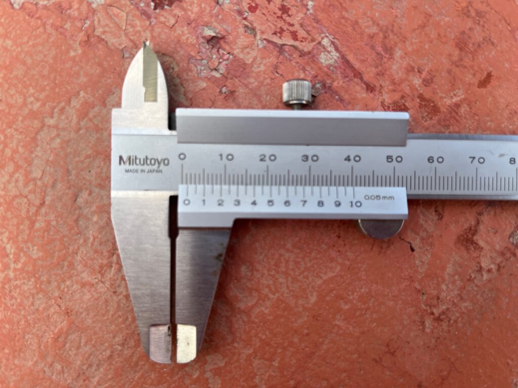
I decided to try and measure the thickness, just for information which was a quick job with the vernier calipers.
The thickness was 1.3mm more or less. Not insignificant.
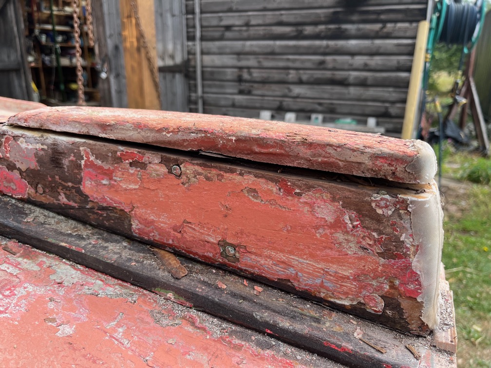
I also noticed whilst trimming the backing pad that the skeg had started to lift off the keel and that meant that the wood underneath was unprotected from drying out. That meant removing the skeg entirely so that i could coat the bare wood underneath with penetrating epoxy.
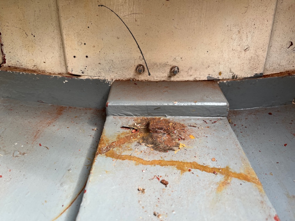
However, this was going to be a problem. There are two bolts protruding through the hog on the inside of the cockpit.
Once here just in front of the transom…
… and one a bit further forward as can bee seen in the above photo just above the bottom of the image. Both are rusted.
I could clearly see where he front one was located in the skeg by the filler that had been put over the top and a little digging with a screwdriver soon prised the fille out revealing the bolt head, also rusted.
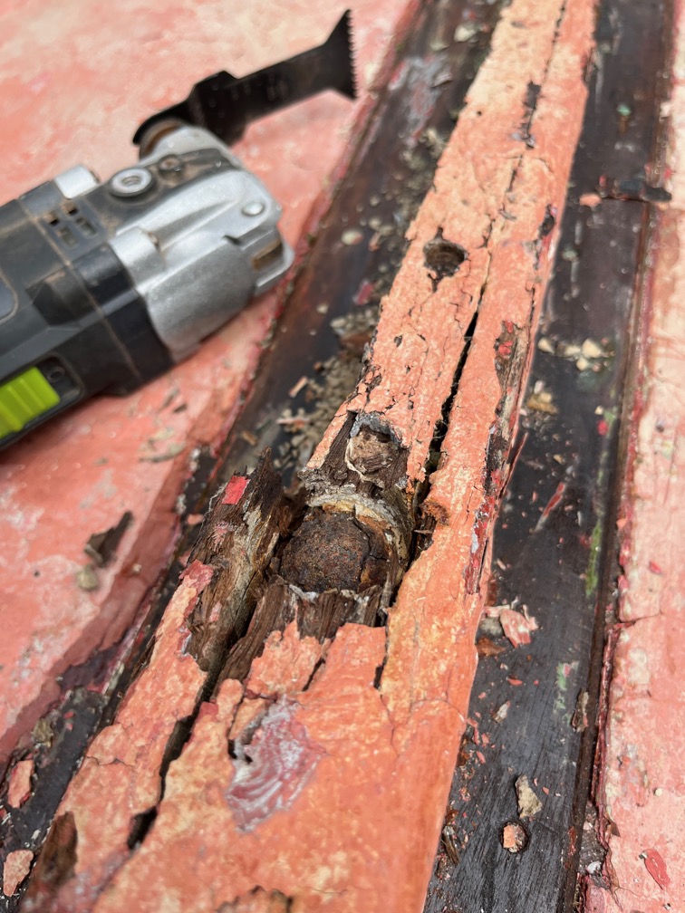
I used the multitool to cut the back portion of the skeg away…
…which revealed the head of the second bolt.
The skeg was very loose on the keel and a little persuasion with a crowbar pulled the whole thing apart.
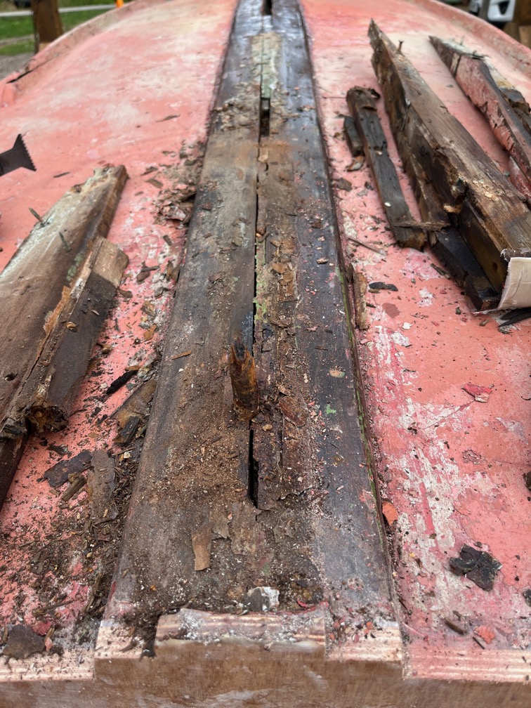
The front bolt came completely away whilst the aft one had waisted in the skeg itself and when the skeg was removed, the upper part of the bolt was left behind, as you can see.
I hit the top of the bolt a few time, bending over the spike of still good metal in the centre but the rusted part of the bolt just shattered away.
This is where the front bolt was, Just rust remains.
I cut off the aft bolt and then used a drift on both bolts, gently hammering the drift which pushed the bolts out through the hog.
They both pulled part of the hog away but that can be repaired with by letting in a graving piece or, more likely given the very restricted access in the cockpit, thickened epoxy.
I cleaned up the slot between the two piece of timber that Charles added, swept up the mess, sanded the timber that was under the skeg and liberally applied penetrating epoxy to prevent drying out and splitting.
I had thought of plugging the two bolt holes with epoxy immediately, but decided not to since it would be difficult to prevent the epoxy from falling out on the inside where I cannot reach for the moment. So, a better bet will be to plug the holes with softwood plugs, using epoxy to glue them in place. The slot between the two piece of timber will also be plugged with a softwood spline, glued in place with epoxy. If the spline is too difficult to make to fit the very aft end where the slot becomes too narrow, then that part will be filled with thickened epoxy.
I have ordered a Cedar plank from which to cut a new skeg. The plank is 32mm thick and I should be able to get two skeg shaped pieces out of this which will be glued together and the epoxied on to the keel one the sheathing and epoxying has been done.
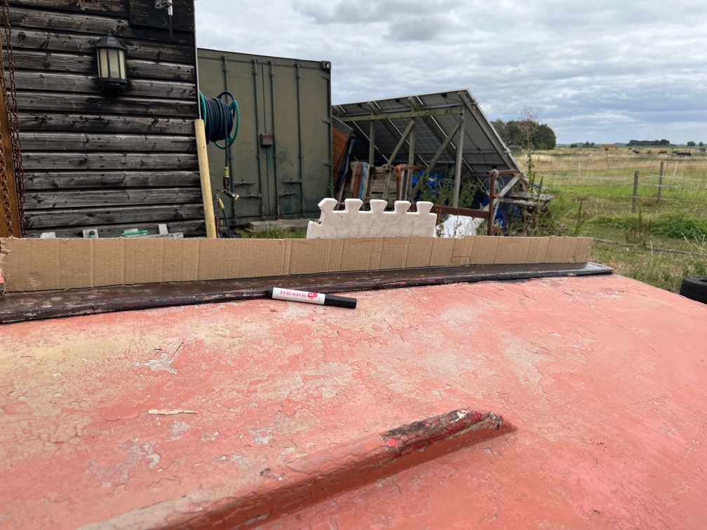
Before making the spline I need a template.
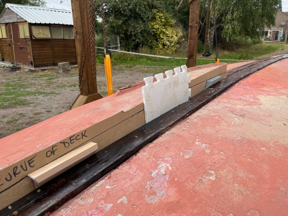
I wedged a piece of cardboard into the slot and used a black marker to draw along the slot where the spline needs to go.
The wedges served two purposes. The first was to push the cardboard against the side of the slot and the second was to stop it from blowing away !
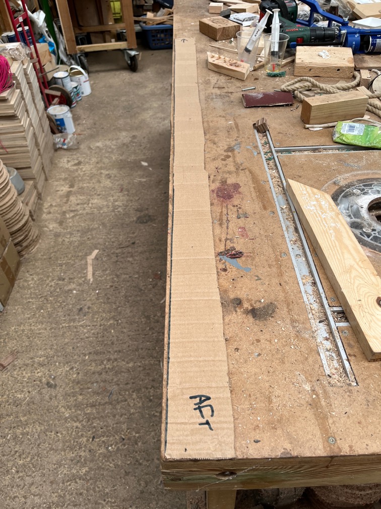
I carefully cut along the line to make the template. As you can see, there isn’t much of a curve, but it needs to be done. I put this away in a safe place for later.
It has been some considerable time since I last carried out any sustained work on Shoal Waters, primarily due to getting my own boat Naiad ready, then launching her then doing some sailing whilst the weather allowed. I will be unable to sail for the next few weekends, so the time has come to continue with the Shoal Waters’ refurbishment.
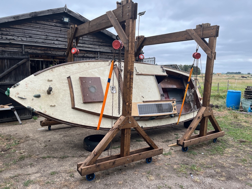
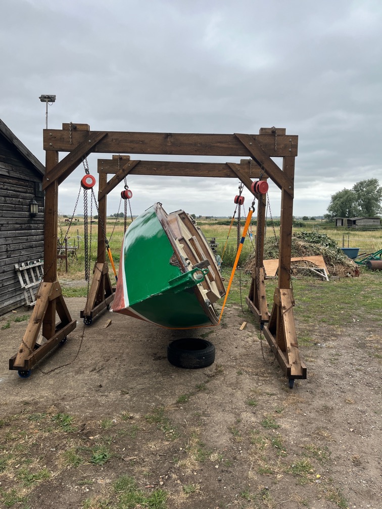
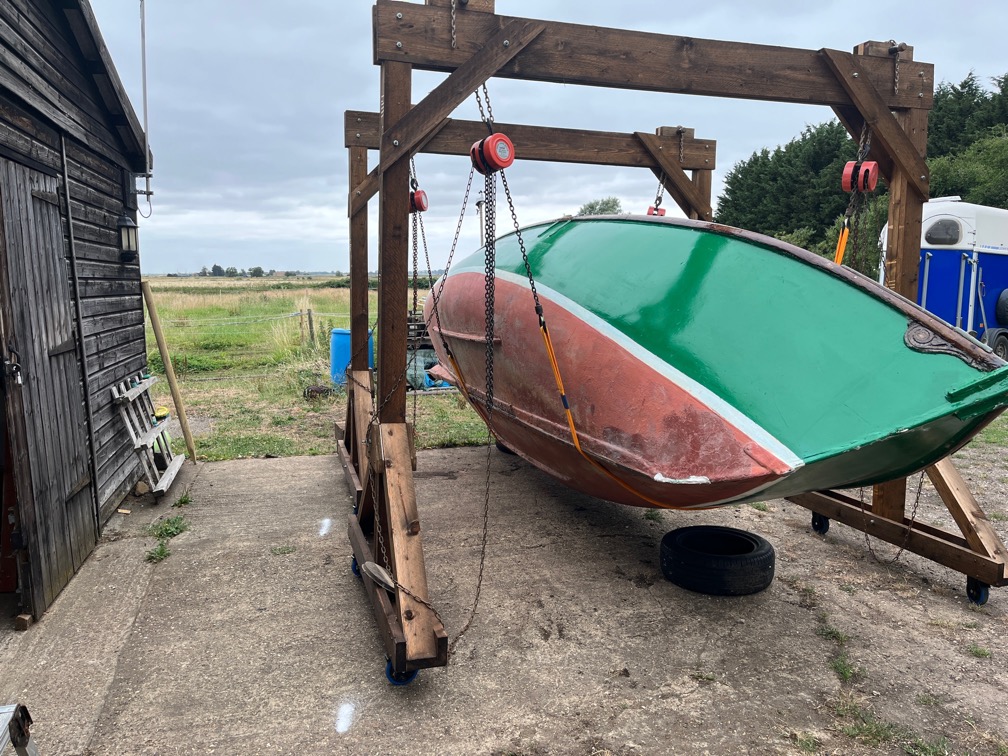
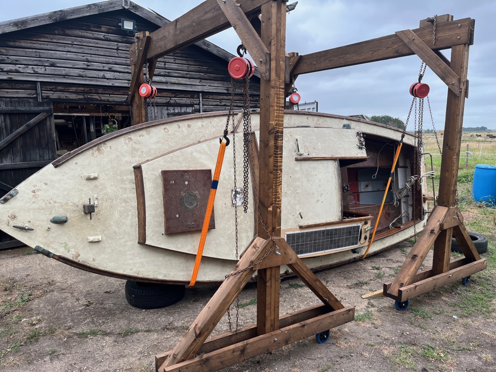
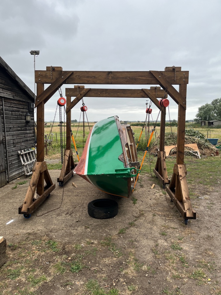
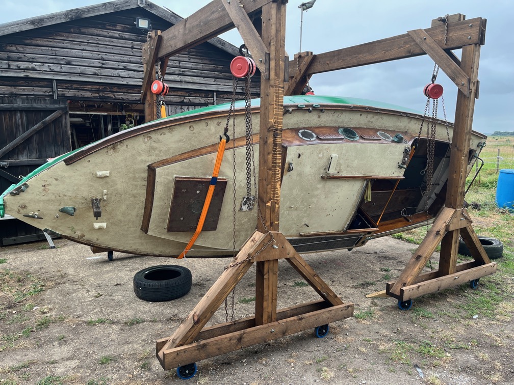
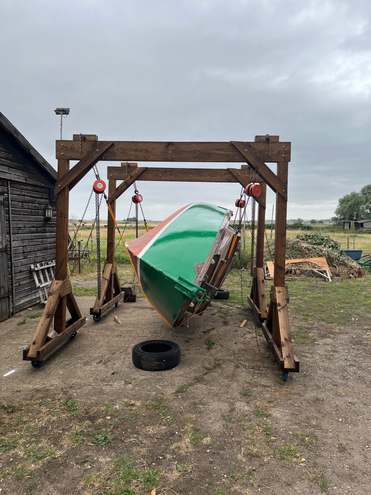
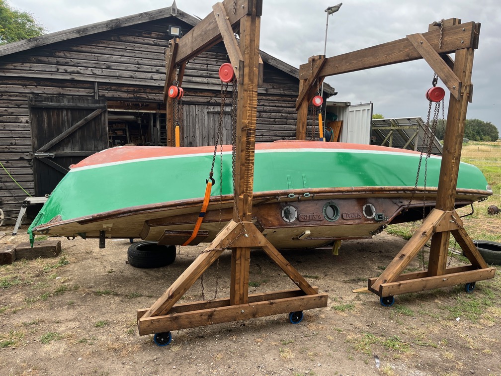
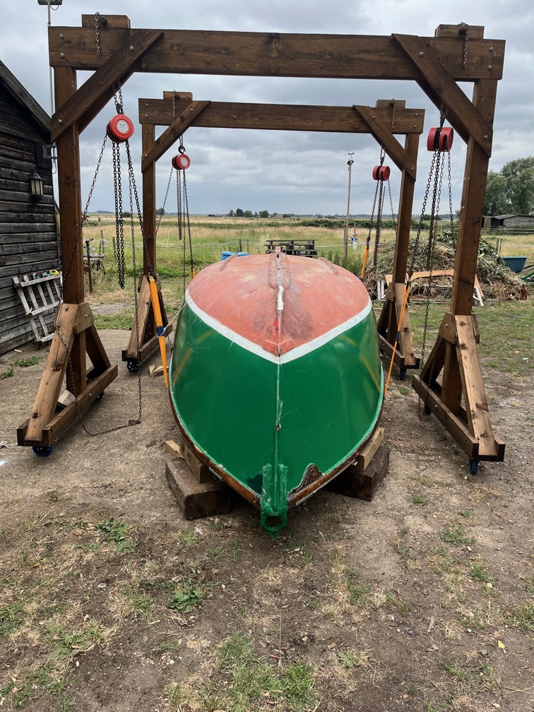
The first task of the day is to invert the boat since it is the hull upon which I need to work next and that is not possible when she is the correct way up. So, the gantry cranes were rigged and put into position, Shoal Waters on the working trailer positioned and strops attached to the hoists and then the tedious process started.
Down on one side and up on the other.
I dislike this part of boat maintenance intensely.
I know it is necessary but that still doesn’t mean I like it much.
More and more she tipped over.
And despite looking like she would tip right over about here, she did not.
It was only at this point that she finally tipped over the center of gravity and came to rest on the strops and chains on the other side.
This shows just how much the topsides have to cant over before the tipping point is reached.
Then it is lowering down instead of lifting up, again little by little. No need to rush, we were not in a hurry.
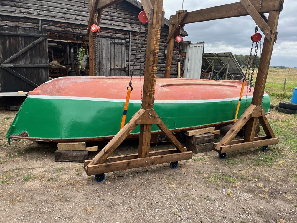
Until she was finally down and resting on blocks.
This is as low as she can be, the main hatch frame is a centimetre or so above the concrete. Time to get to work.
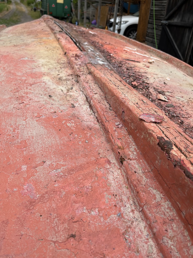
The first task is to remove the paint and antifouling from the keel. Parts of it, as you can see here, are already bare, the accumulation of paint having chipped off sometime since she was last in the water.
I set to with a sharp paint scraper and it didn’t take long to remove the majority of the paint from one side of the keel. This is the after photo…
…and this is the before picture. Quite a difference.
It is quite evident that these pieces of wood are the pieces that were first put onto the hull after she was delivered to Charles Stock way back in 1963. In his book “Sailing Just for Fun” Charles says this:
Fitting a shallow keel below the moulded hull to protect it when grounding or hauled ashore, for the winter, was the first problem. Shaping a solid piece of wood was beyond my skill so I used two pieces of wood three inches by a half inch, laid each side of the keel ridge and glued and fixed into the hull laminates and hog with alternate gripfast nails and brass screws every three inches (p25)
And surprisingly the nails and screws are in better condition than I expected.
There is a lot of evidence of repaired dings and scrapes along these two pieces of timber, but that was the reason for them being there in the first place.
The keel looks to be in poor condition when first viewed but this was not the case.
Here is the keel with most of the paint removed and having been given a fairly aggressive sanding using an angle grinder and a sanding disk.
Finally, the exposed wood was liberally coated with the penetrating epoxy I have. This was an important step in the cleaning up of the keel. We have just had several week of hot weather and although is wasn’t hot today, the forecast indicates that the temperature will rise again over the next few days and the last thing I want to happen is for the exposed timber to dry out and split.
Hence the epoxy coating. I’ll probably put another coat on tomorrow, just to ensure good penetration.
This will not be a problem for the hull itself as this is made of four 2.5mm layers of Agba that have been glued together in a process known as hot moulding. This heats up the wood and glue and the glue then seeps into the wood. It is unlikely that the hull will dry out and split even in the hot weather.
The next task on the list is to measure the distance from the underside of the gunwale to the lower edge of the boot top so that when I get to the point of repainting I know where to put the different layers of paint.
I noticed that the bilge runners were not in good shape as I worked on the keel.
This is an example. Both runners have cracks and crushed sections and will need some serious remedial work. The damage to the keel, skeg, forefoot and bilge runners is not at all surprising when you consider that Shoal Waters spent most of her life to date on drying moorings where the ground consisted of shingle and mud.
Every time the tide went out, she would be deposited on the shingle and every time the tide rose, she would be lifted off the shingle. Now, in calm weather that would not be a problem, but even in a moderate slop, the waves would bounce the boat on the ground for a few minutes until she was firmly aground, or floating.
And that is when the majority of the damage occured.
Before I turn Shoal Waters over for her hull work, I need to finish a few things first, primarily the backing board for the pintle.
I’m fairly sure that the screws in the two lower holes in the pintle come out above the keel timber, or would if they were longer. I can see the remains of two prior screws that have been degraded.
I drilled the holes right through the transom, and sure enough, they were above the keel, although not by a lot in the case of the one one the port side. I found two 6mm bolts of a suitable length as you can see here.
This is good news since these two holes are below the waterline and I don’t like using screws since they are difficult to get and maintain a good seal. The intention is to open out the holes to 13mm, fill them with thickened epoxy and then drill the correct 6mm hole through the centre of the epoxy. This ensures a very good seal between the wood and the epoxy and allows the use of butyl tape to make a good seal between the pintle, bolt and the epoxy.
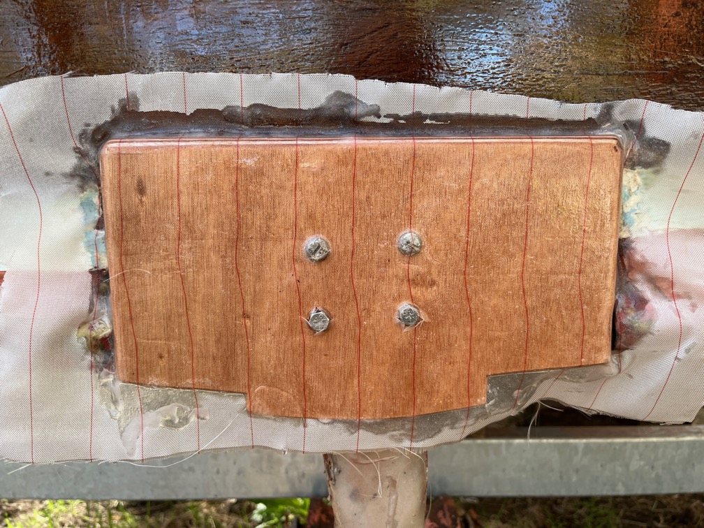
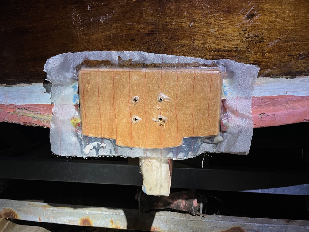
On to the backing pad itself. A template for this was constructed out of low quality plywood and from this two pieces cut out of the 6mm marine plywood and glued together. The mounting holes were transferred to the new pad by holding up the pad to the transom in the correct place and wedging it there with a post. A crosspoint screwdriver with a diameter of 6mm was pushed firmly through one of the holes from the inside, marking the plywood.
After that holes was drilled the pad was bolted in place os that the other holes could be marked. The bare transom was coated with neat epoxy, as was the outer face of the pad and lots of thickened epoxy spread on the pack of the pad. And by lots I really do mean lots of thickened epoxy. The bolts were put in place and tightened up squeezing out about half of the epoxy. This was deliberate as the transom was not entirely flat and having an excess of epoxy that squeezed out meant that there would be not gaps or voids between the transom and the pad. Finally, peel ply was put onto the pad and neat epoxy used to thorughly wet it out.
After a few hours, when the epoxy was sufficiently cured to stay in place without the bolts, they were removed through holes that I’d cut in the peel ply before laying it on.
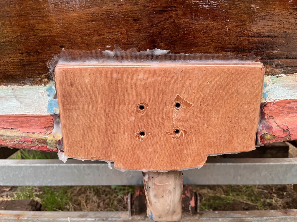
The following day the peel ply was removed. The excess will be tidied up after the epoxy work is completed, which is not now.
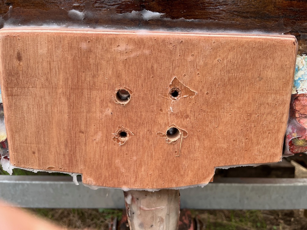
Two of the holes, one upper and one lower, were drilled out to 13mm, firstly using a stepped bit to 10mm and then by drilling successively larger bits through the holes.
This is the view from the inside. Now you may be asking yourselves why only two of the holes? The answer is so that I can use the other two to fit the pintle and mark the correct position of the new holes in the epoxy. Once these two holes are done the other two holes will be similarly treated.
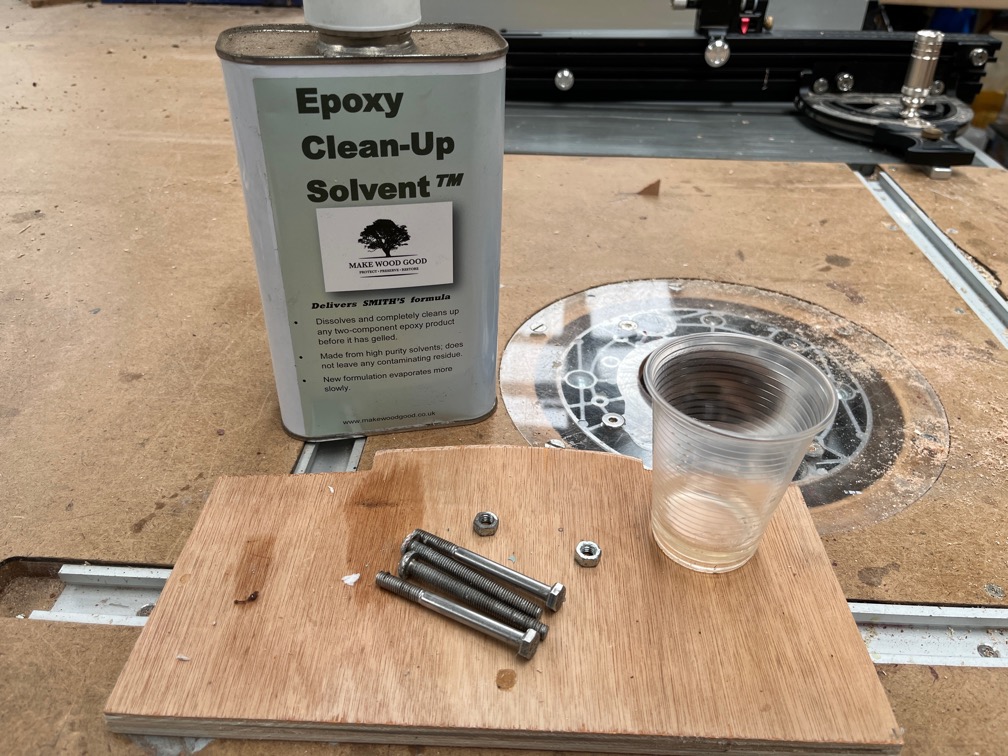
I did, however, have to spend some time cleaning the curing epoxy off the bolts.
I have an epoxy solvent that does the job fairly well but only on epoxy that is still soft. Once it is hard you need to use heat to soften the epoxy enough to scrape it off. The bolts cleaned up well, ready to be used once the rest of the epoxy work is done.