2026-02-22 – More Epoxy Work & Glue Ups

Today was going to be a little bitty since the epoxy and glue work that needed doing meant that other tasks had to wait until the epoxy set cured and the glue dried properly. The varnish work was completed before breakfast. Later I made a start on glueing things.

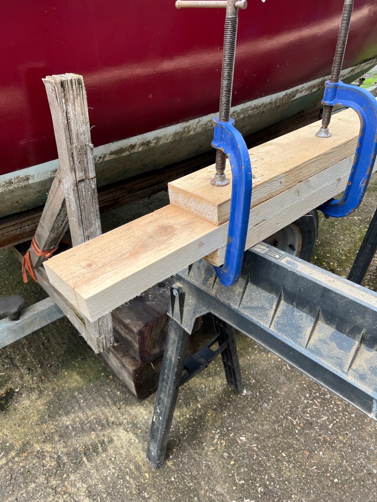
The first item on the list is the block extender. I placed the new piece on top of the block and drew the outline of the block on the underside with a soft pencil, then sanded the sides of the block away until it was down to the pencilled line. This piece was glued on with a temporary screw since clamping is not possible just here. As with all the other temporary screws, the holes will be filled later.

Next up were the case sides. The adjustments that were made during the dry fit meant that unsealed plywood edges were exposed and these all had to be coated with neat epoxy.

This means that not further work on the case can be carried out until the new piece of wood on the aft block is firmly stuck and then shaped and the epoxy on the cases has cured.

The new plywood on the transom needed another coat of stain as they were still obviously lighter that the rest of the transom.

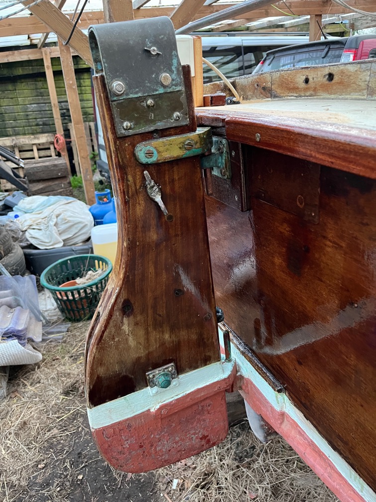
Something I did forget when I had the stain out yesterday was the gudgeon backing pad.

So that was next. This is the second coat and I think that one more will be enough to match the transom.

Time for a cup of tea.

Once the glue had set enough to withstand some strong sanding, I took a sanding disk on an angle grinder and the belt sander to shape the aft block.

It’ not perfect just yet, for that I need the case sides in place.

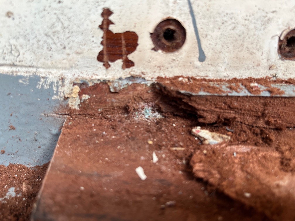
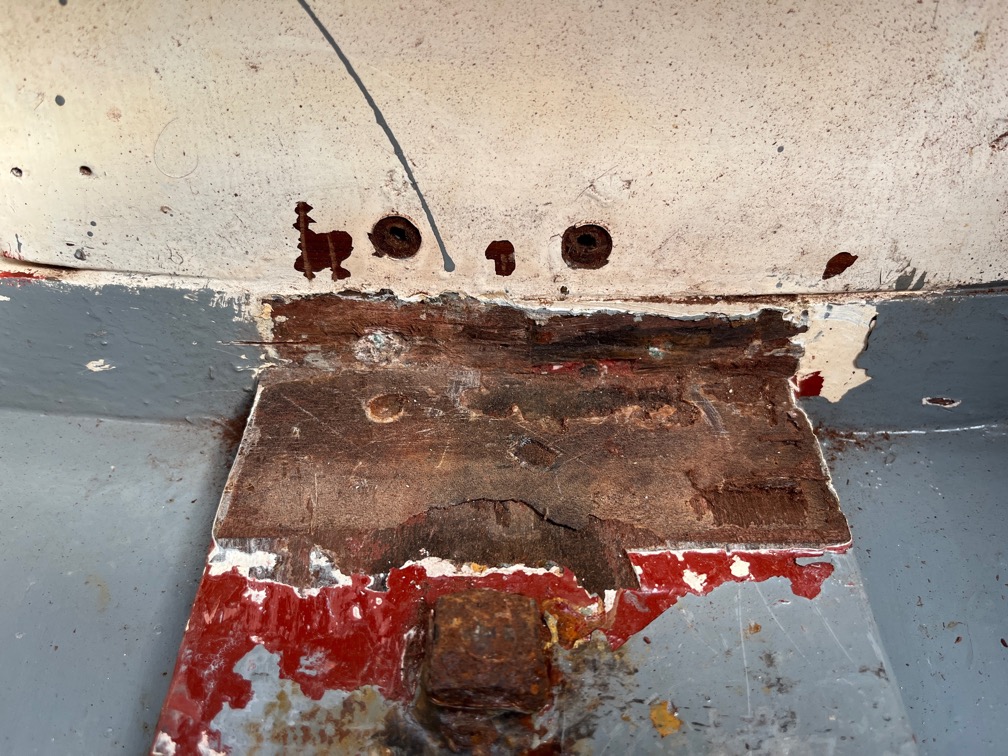
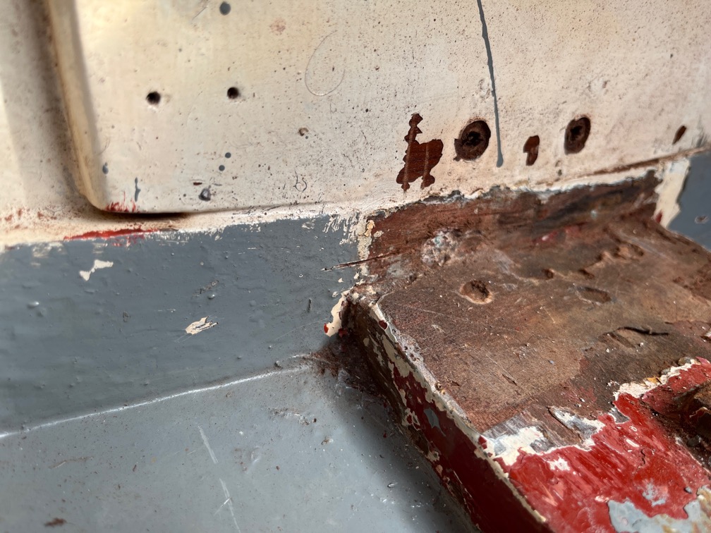
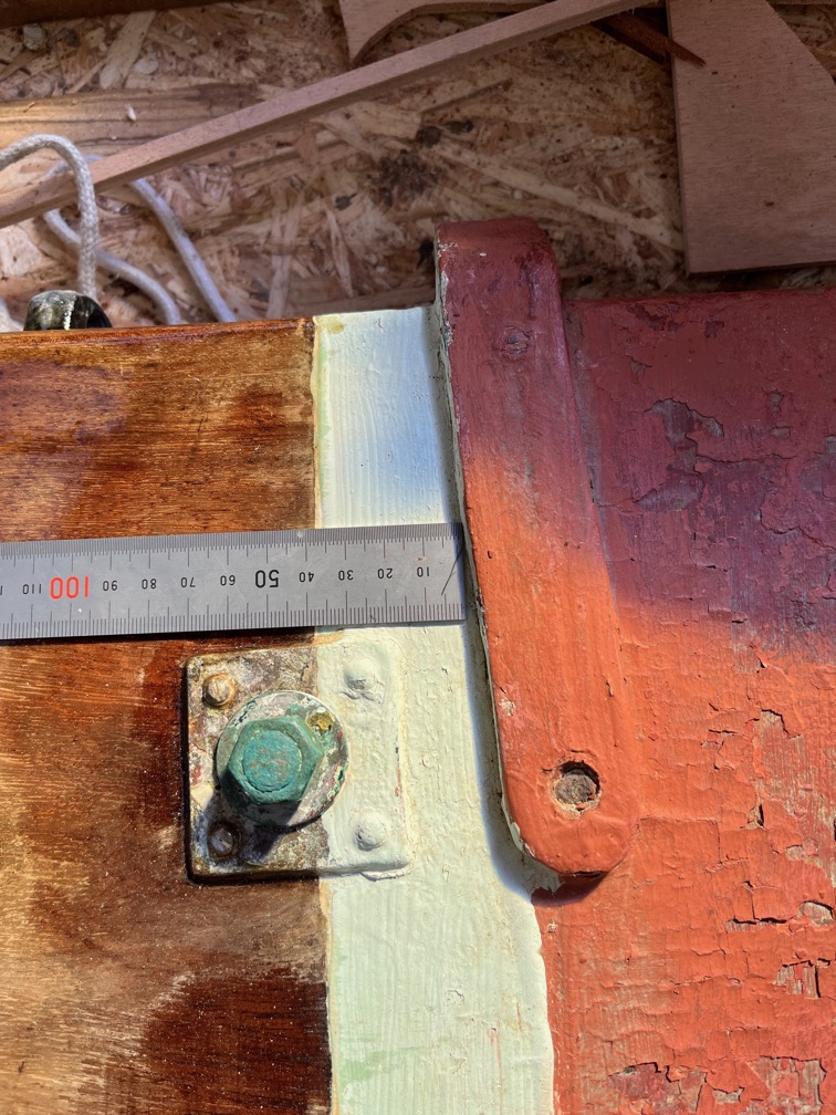
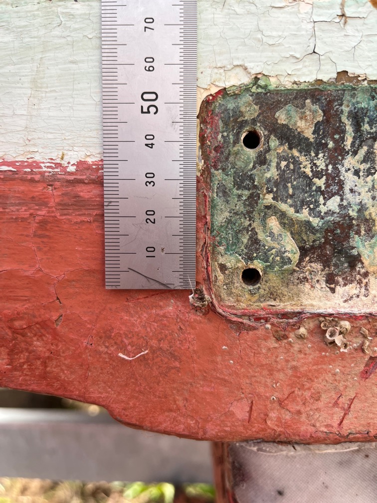
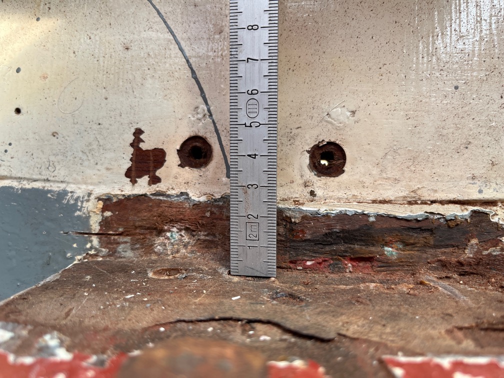
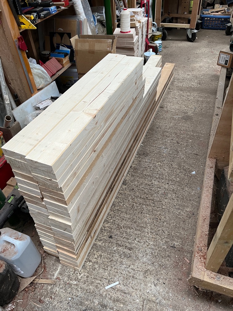
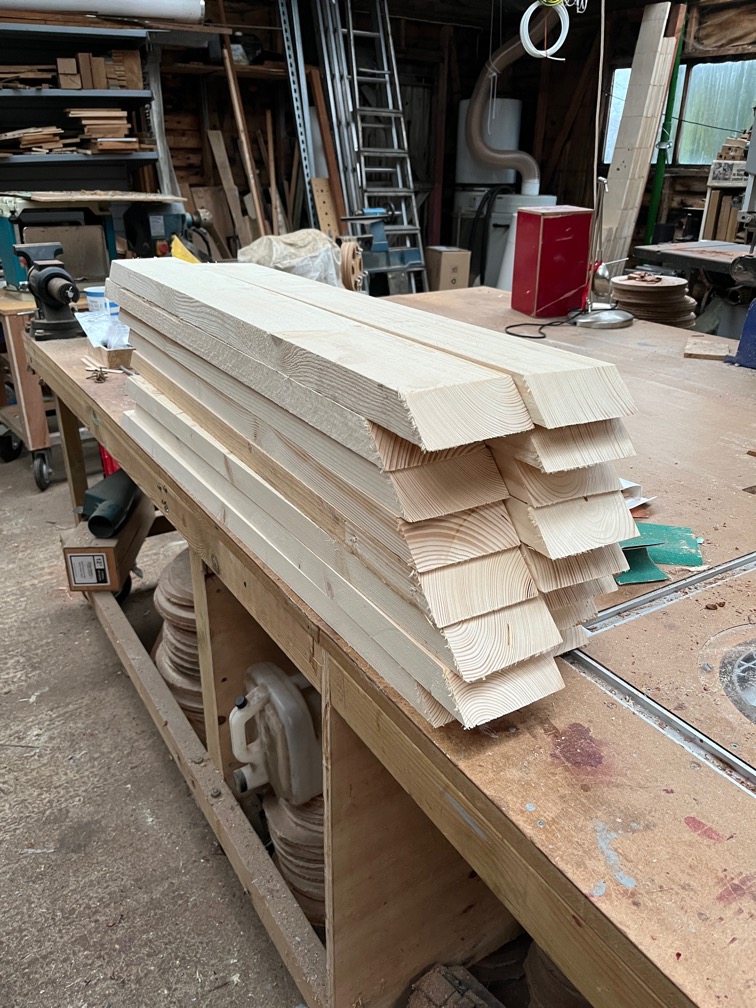
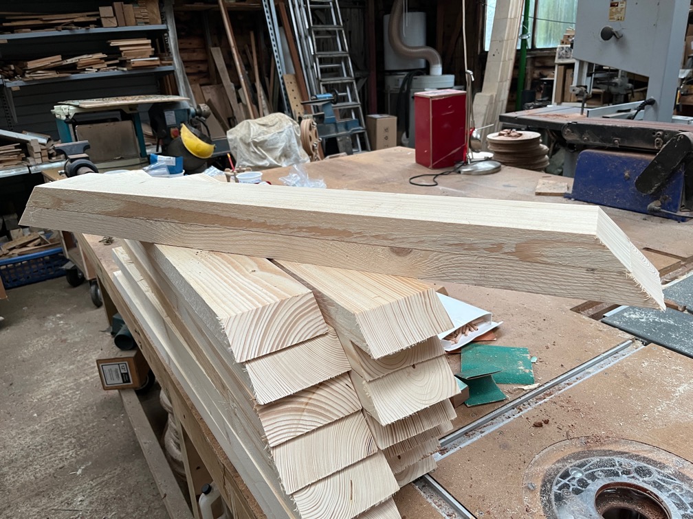
Now comes the task of laminating a new rubbing strake on the transom. The original was 30mm wide and as you can see, the centre line for the screws goes straight through the transom/deck joint. This is not good. You can see in the photo above that the joint has cracked and I’ve no doubt that this was due to the screw acting like a small wedge as it was screwed in. The crack may not have occurred immediately, but the pressure trying to open the joint was there until the point that the glue failed.

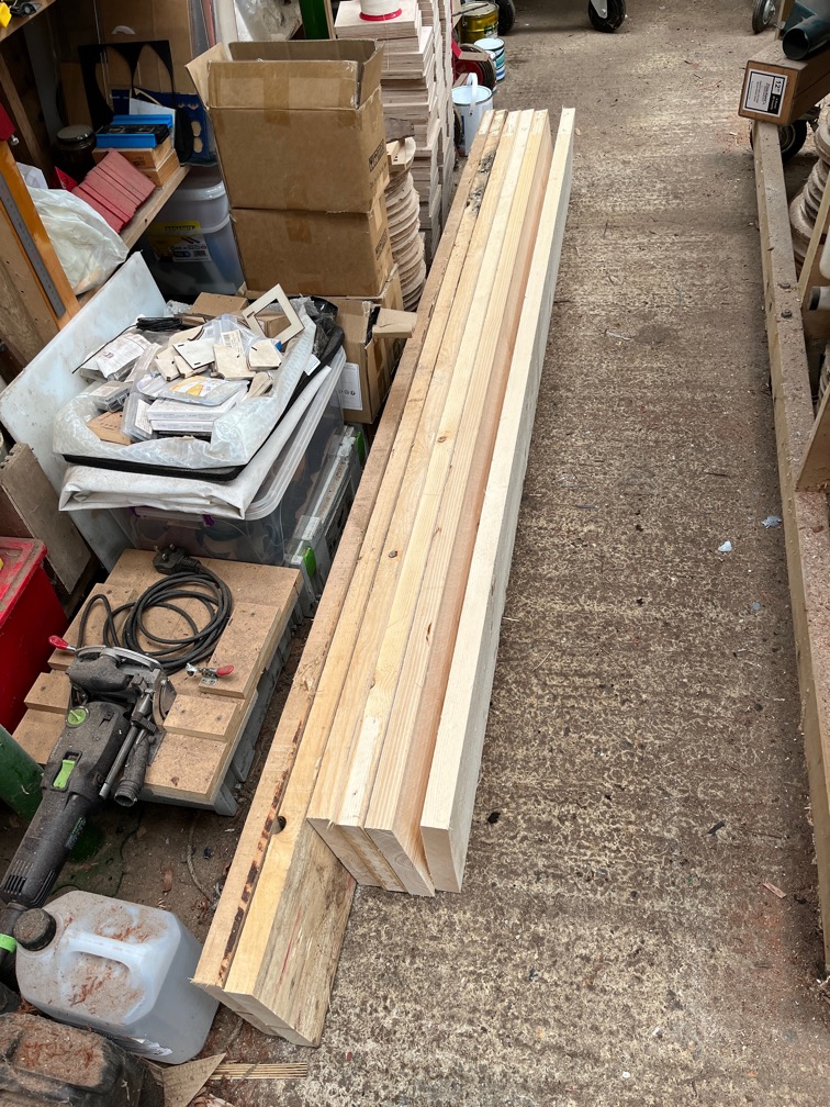
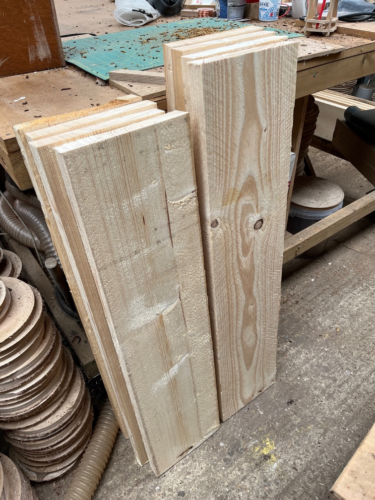
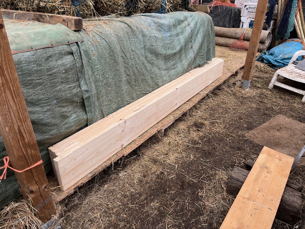
So, I cut the laminates such that the strake is 40mm wide and this will move the screw holes down into the top of the transom.

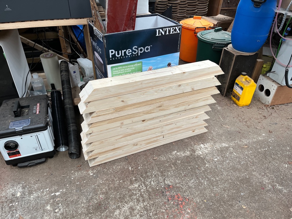
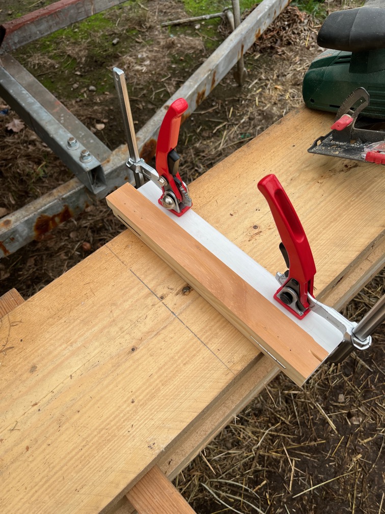
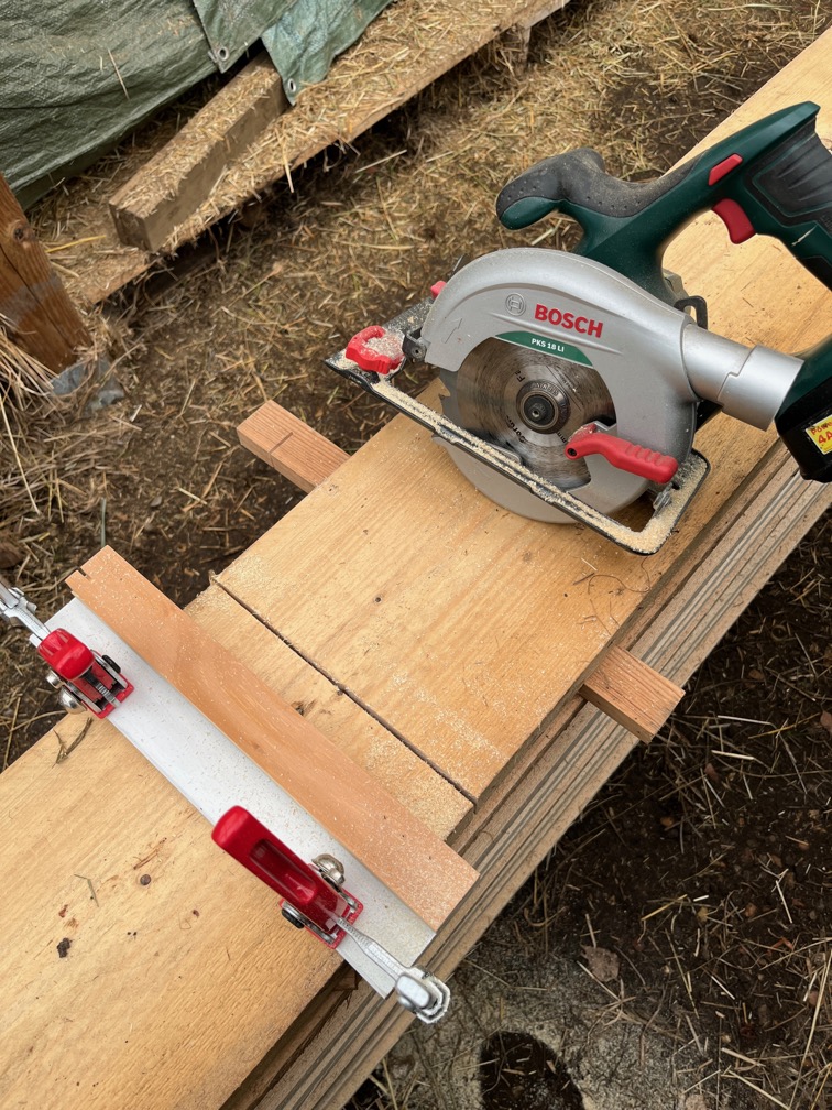
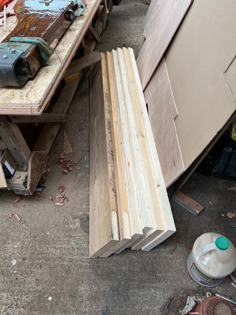
The next task after cutting the laminates was to make the jig. I used the cardboard template that I made previously to draw the curve on a suitable piece of gash wood, in this case MDF, then screwed blocks to the board against which the laminates will be clamped.

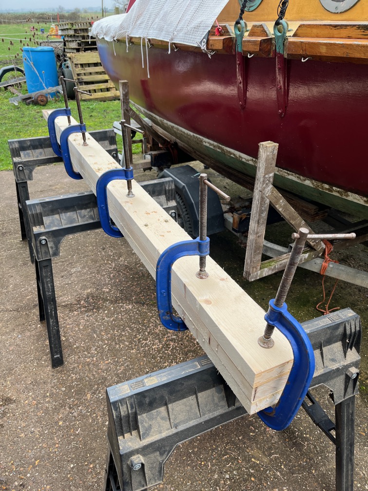
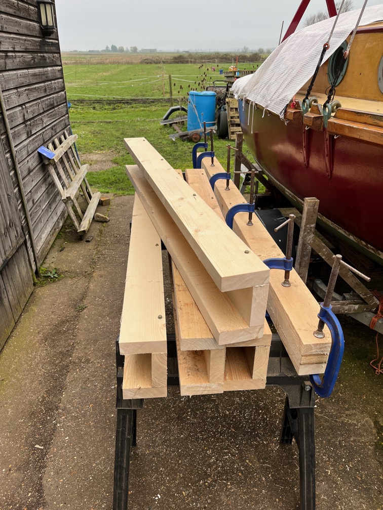
Like this. The jig was covered in film to prevent the laminates from being glued to the jig and the laminates covered in glue on both sides except for the outermost ones which only had glue on one face. These were stacked and put into the jig and clamped in place.

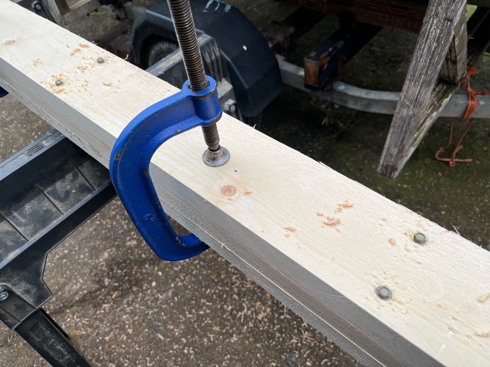
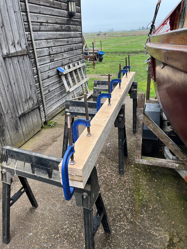
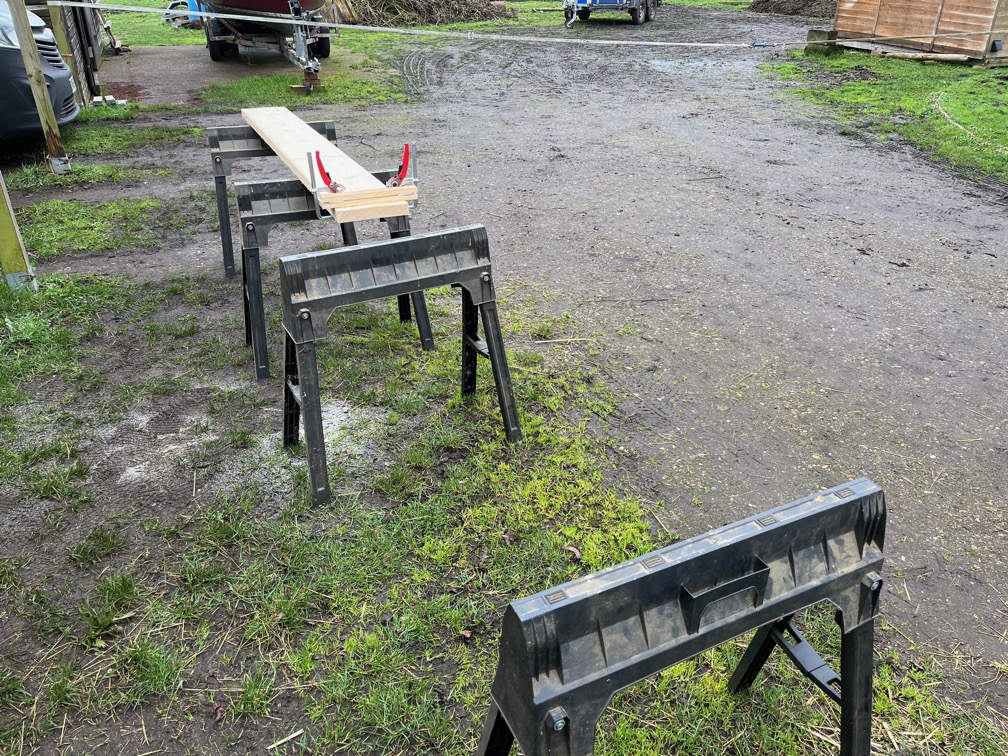
Laminating can take a fair number of cramps.

And you can never have too many cramps in the boat building business.

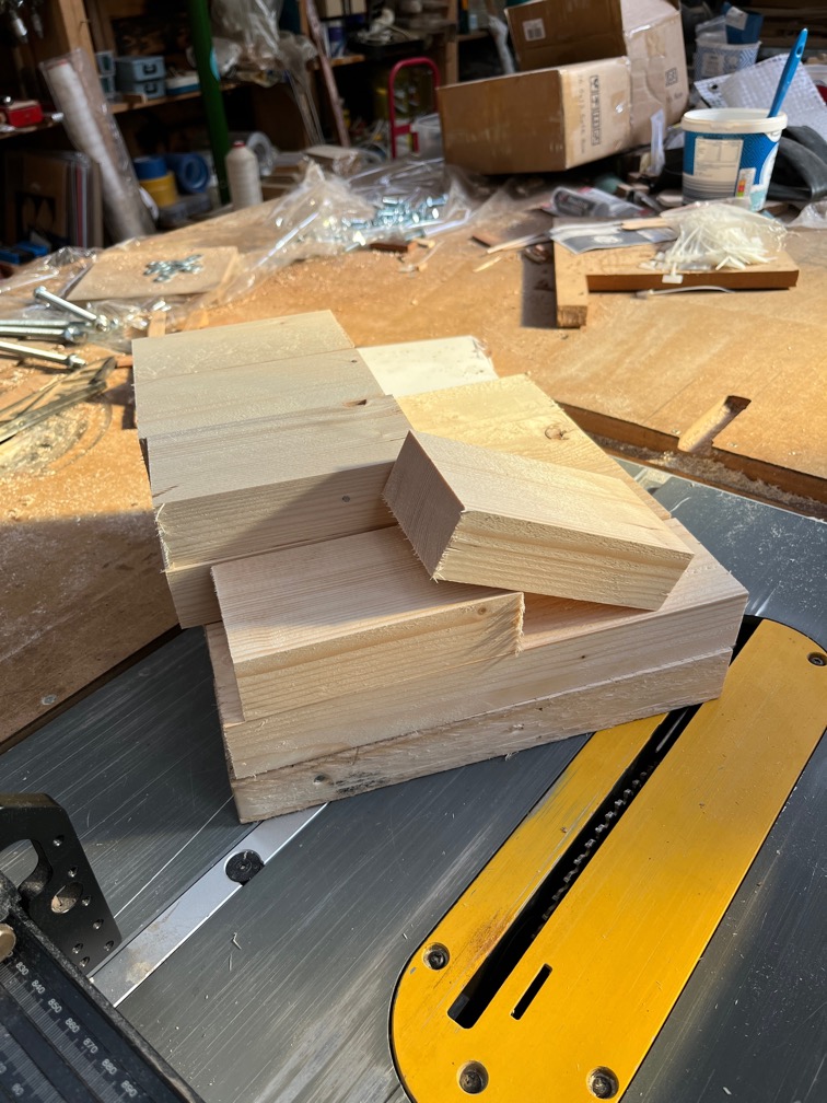
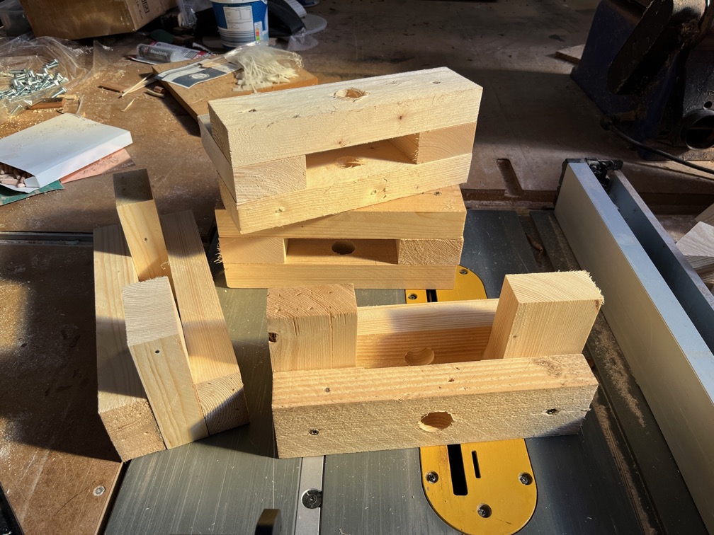
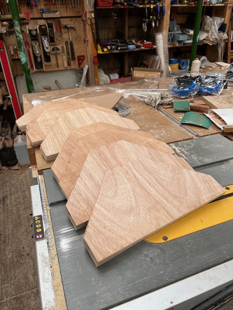
One more glue up was required and that is the above which will form the missing top of the centerplate case as I did not have a single piece the correct size.

So far, a good day.

Time for a cup of tea.

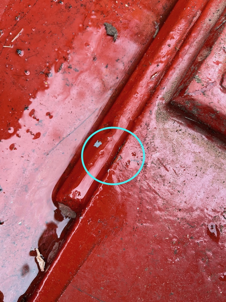
Annoyingly, as I was drinking my tea I realised that I had forgotten to coat one of the centerplate case sides on one end. So I mixed up another shot of epoxy and rectified that omission.

This was the missed section and once I had coated that I still had a lot of epoxy left. I went around trying to find things where I could use up the remainder of the shot rather than waste it. I didn’t have a lot of time for this as I used the fast hardener and I could feel the heat of the reaction as I held the plastic cup in which I mixed the epoxy. I had perhaps five minutes before it became unusable.

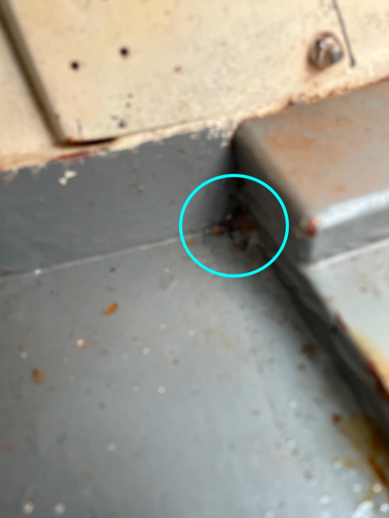
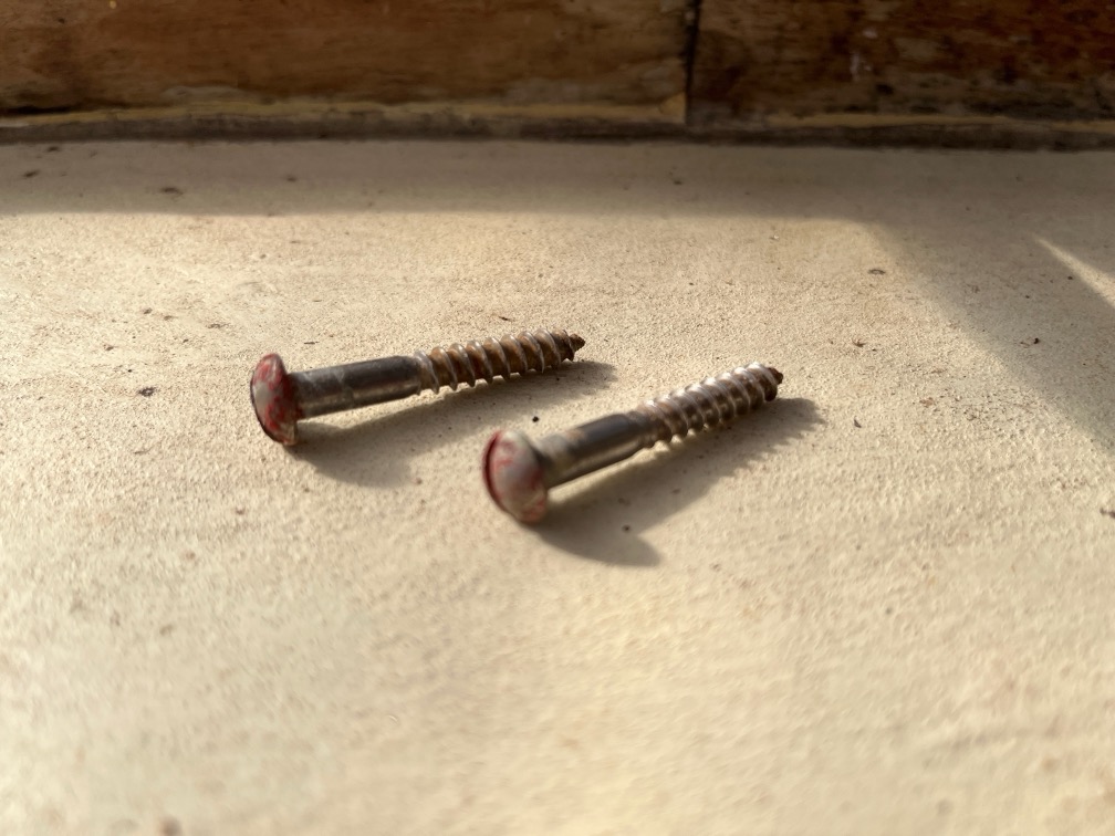
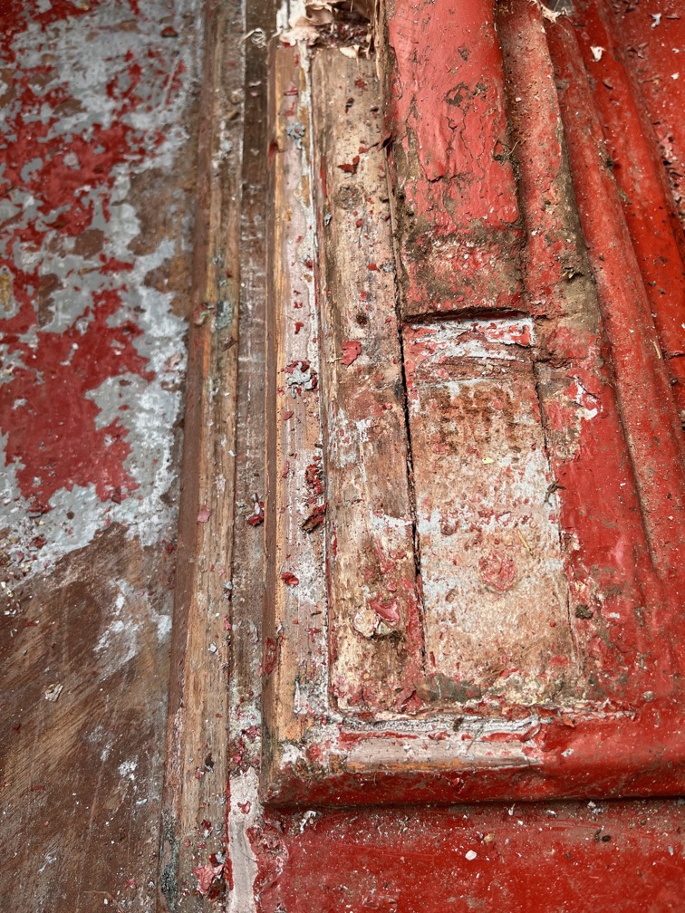
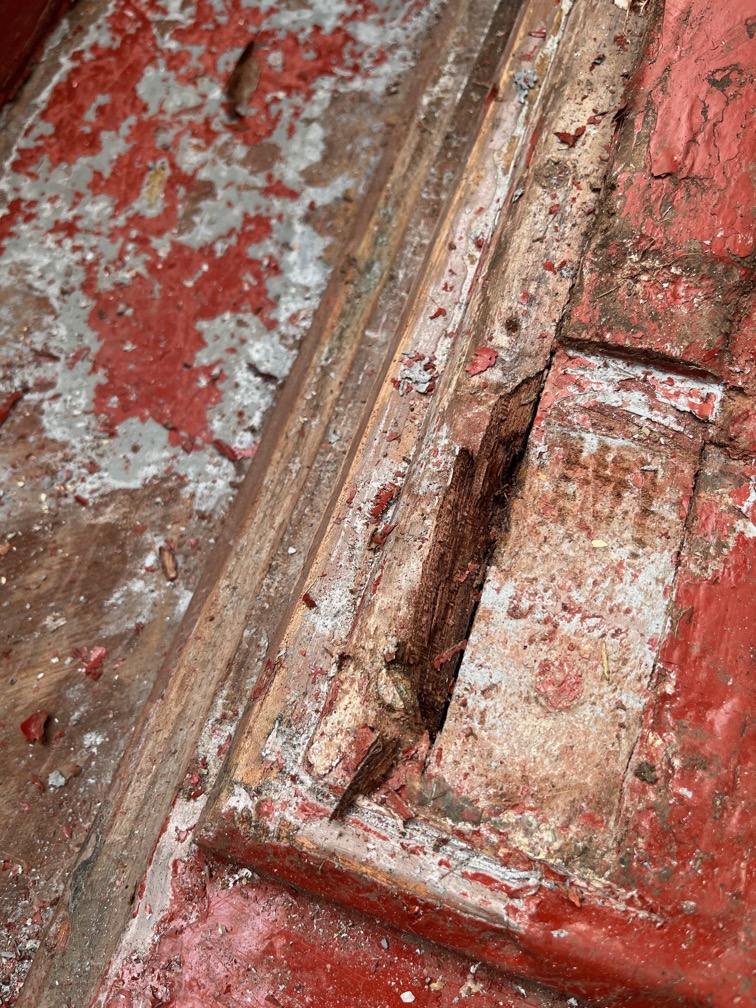
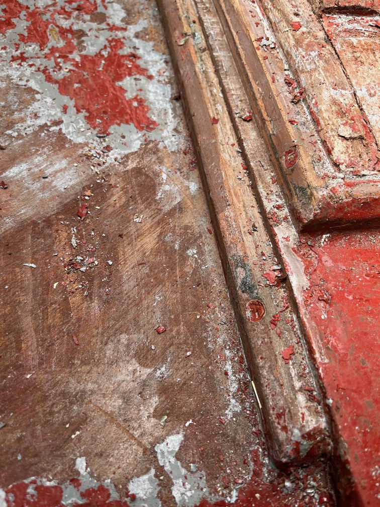
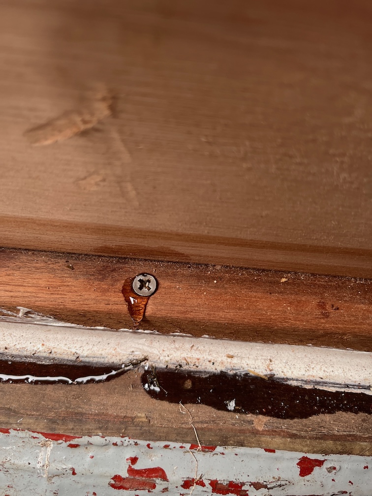
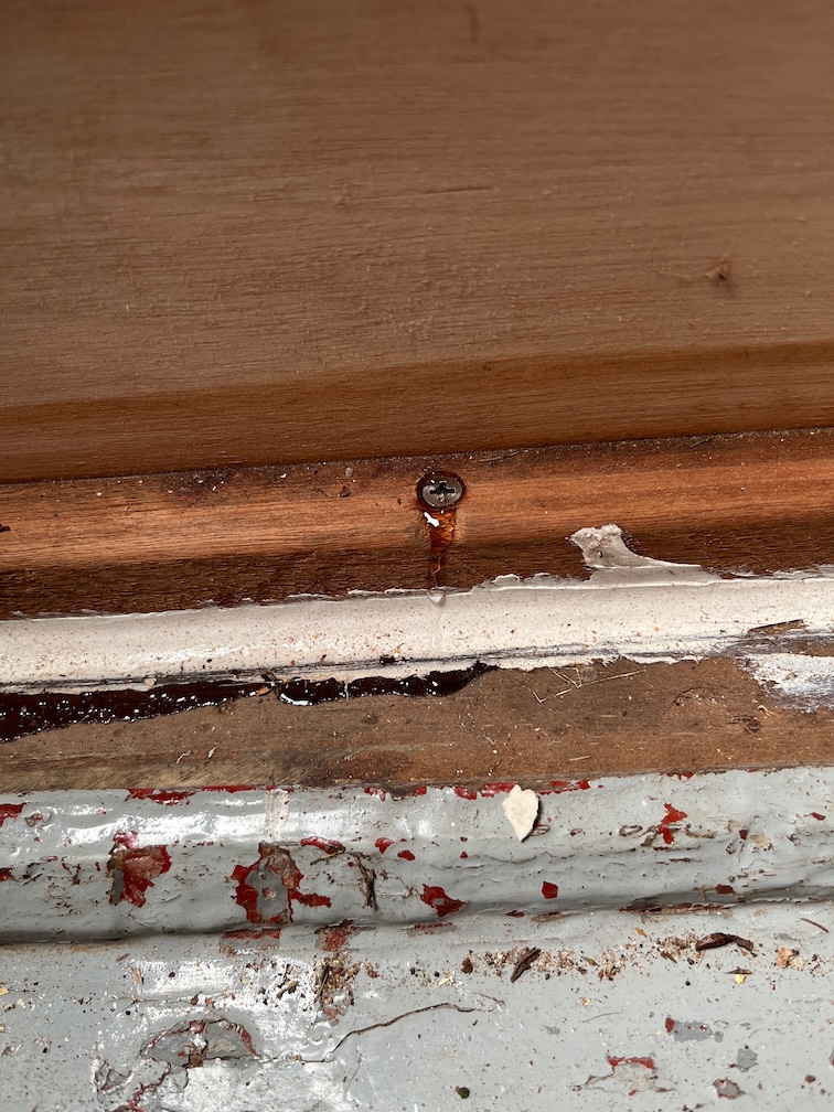
Some went in this screw hole.

And I used some more coating the top of the transom where the rubbing strake had been and also the edge of the plywood that makes up the aft deck.

Since I was in a hurry I didn’t clean these areas up first, just slapped on the rapidly curing epoxy. If it subsequently falls off when I’m fitting the new rubbing strake, then I’ll just clean up the area and put more fresh on.

I think that is all the construction, epoxy and glueing work done for today and I think I have covered everything that was on the critical path, so I can get one with other tasks now the were previously blocked.

Back to my cup of tea.

Have had a break I started on the Shoal Waters name plate.

The old fixing holes were plugged and once the glue had dried sufficiently, the plugs were sanded flush. The board was then mounted on the CNC Router table and given a surface cut just deep enough to cover the entire surface.

Then a 6mm bit was used to cut out the larger areas of waste.

Followed by 1/8″ bit.

Finally a 1/16″ bit was used to finish the letters. I messed up the positioning of the two right hand side mounting holes, I’ll have to fix that later. The board was given a light sanding to remove any fuzzies and taken inside to warm up.

After about an hour the board was warm so I applied a coat of clear epoxy.

The letters are 3mm deep and will be filled with epoxy coloured with white pigment. However, if you skip this coating stage you run the risk of the coloured epoxy bleeding in to the surrounding wood, especially if it is porous. The clear coating serves as a barrier to prevent the bleeding.

The epoxy used will not be cured for 24 hours, so the next stage of this task will not be carried out until tomorrow evening at the earliest.

Time for a cup of tea.
2026-02-21 – Transom & Centerplate Case

I made an early start thing morning, but only for the varnishing which I carried out before breakfast. After that I started making some muffins. English ones not the American kind.

Spoiler alert, this is how they came out a couple of hours later.

There were eight, but we had to try them out. This is the first time I’ve made muffins like this and they worked out well.

Whilst the transom was still warming up, it might have been reading 13º C at the weather station but the mass of the boat takes a little time to warm up, I put masking tape on the graving pieces…

…and on the transom. Epoxy will squeeze out of the seams when the graving pieces are put in and the tape helps to prevent that from getting on the rest of the transom.

I used an infrared temperature meter to check the temperature of the transom and once it had reached 13º C I applied neat epoxy to all the edges of the graving pieces and the recesses, then applied some thickened epoxy to the mating surfaces. This was to fill any gaps between the mating surfaces and was just a thin layer, not loads. I used the fast hardener since I want this to kick off quickly and to be cured before the temperature drops below 10ºC. You can see where I have scraped off the squeeze out.

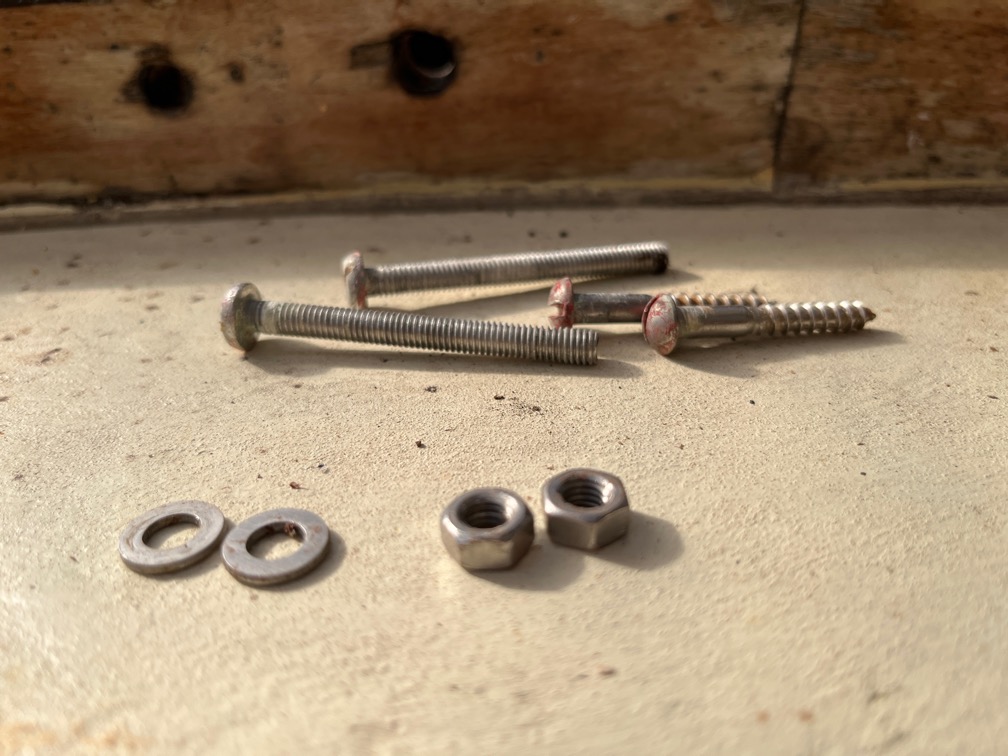
You may also notice that I’ve used some modified truss head screws to hold the graving pieces in place since there is no practical way to clamp them. I’ll fill in the screw holes once the epoxy has reached full strength.

It is imperative to epoxy all the edges of the plywood to prevent the inner cores from soaking up water. Some of the remaining epoxy was liberally spread in the top of the new transom piece.

It is also fairly important to remove the tape before the epoxy hardens too much. When the seams stop oozing then it’s time to get the tape off. I will have to apply more stain to the graving pieces, I’ll do that later.

Once that was out of the way it was time to dry fit the case sides. they are a pretty good fit, just a couple of slight modifications to make them fit without needing a mallet.

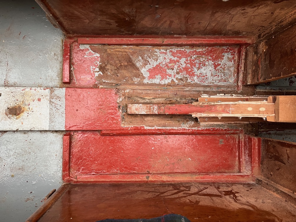
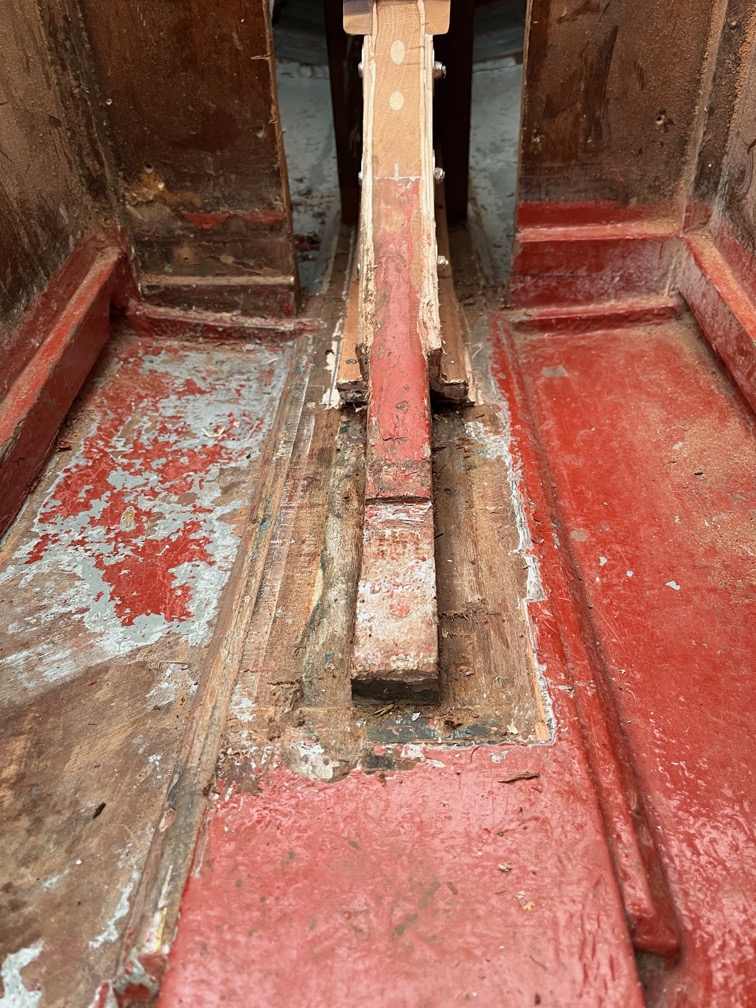
The new top part of the aft block is too short and I will have to make a piece to fit on top of this to bring it up to the level of the case sides.

The pivot bolt almost fitted through but I did have to widen the hole in the starboard side slightly to allow the bolt to go in easily. It is out of focus, but you can see the pivot spacer in position. I wrapped a wire coat hanger around the spacer to be able to get it in the correct place and so that it doesn’t drop out when I take the bolt out. I needed to tighten this up to the point where the spacer is hard against the case sides as this draws the sides together a little.

I was delighted to see that the two original top pieces that came off the old case fit perfectly on the new on. I must be doing something right.

There is virtually no step between the new case and the tops.

The top piece that went in here was destroyed in the removal, unfortunately, but I have some Sapele left and can make up another one easily enough.

I stopped at this point as I made three mistakes one after the other. Getting tired and there isn’t really any hurry any more.

Time for a cup of tea.

So then, moving on…

I put another coat of stain on the graving pieces and then gave the entire transom another coat of the stain. As you can see, it has made a complete difference. The graving pieces are not so noticeable now and the entire transom is darker. I expect that this will lighten a little once it has dried, but it is looking pretty good.

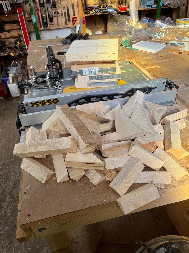
These are the cutoffs from when I made the new aft block top and I can use one one them to make the piece I need to heighten the block.

Like this. The new piece will be glued onto the top of the block and shaped to fit. Once the case sides have been properly fitted I’ll cut it down to the correct height since it is deliberately too high.

Finally, for work on Shoal Waters today, I removed the end pieces of the rubbing strake at the top of the transom, making space for the new one once I have made it.

The deck and transom under the rubbing strake seems to be in good condition. This is the area where the repair was made…

…and this looks to be original.

Time for a cup of tea.
2026-02-20 – Odds and Ends

With the weather forecast for the next few days indicating that the temperature is going to be 10º C or above, I have a shed load of things to get done on Shoal Waters. Here’s the list in no particular order:

  1. Sand the transom and the graving pieces.
  2. Stain the transom & graving pieces.
  3. Epoxy in the three graving pieces.
  4. Dry fit the centerplate case sides & adjust where required.
  5. Fit the case sides.
  6. Cut back the aft deck to good wood.
  7. Epoxy glue in plywood to repair the aft deck.
  8. Fit the through deck fitting for the aft navigation light.
  9. Laminate a new rubbing strake for the top of the transom.
  10. Epoxy glue the backing pad on the transom that was cut away for access.
  11. Carve ‘Shoal Waters’ into the old name plate.
  12. Carve ‘Maldon’ on to a new name plate or the existing one. TBD

That is what I can think of right now and it is a fair bit of work to get done in the time I have.

So, after the morning varnish application, during a tea break, I made a cardboard template for the curve of the aft deck.

The idea is to laminate a new rubbing strake for the entire width of the transom. The pieces I did not cut off before will be removed and replaced by this new one. The reasoning is that I will need to remove the rubbing strake the next time Shoal Waters is out of the water for maintenance so that I can repair the repair that is giving soft returns. If I make an entire new timber, screw it on with 304 stainless screws, with a non-adhesive sealant between it and the transom and aft deck edge, then I will be able to remove it without damaging it when the time comes to make the repair. It will be alot easier to make the whole thing rather than pieces here and there.

Hence the template. I’ll also use this template to replace the timber on the transom that is under the aft deck on the inside. This was originally a single piece, I think, but has been cut away in sections over the years. Now that the aft lockers have been removed, there is no need for the timber to be in pieces, so I’ll do the same, laminate a new timber as part of the transom repair next time.

The next task was to clear up the work tables again. Lots of odd pieces of wood went either into the burn barrel of into the useful bits of wood box. I need to find somewhere to put all the pieces of wood that I have cut out or otherwise removed from the boat.

I also need to service the CNC Router as it hasn’t been used in two or three months and it needs to be cleaned up, oiled and the calibration checked before I do any work on the name places. I have several other non-boat projects that need the CNC Laser and the CNC Router and I hope to get these done before the temperature drops again.

The staining needs to be done and dry before the epoxy work and since it was 10º C I took my tea break and applied a coat of stain. To show you the difference I’m putting up a set of three photos showing before, after scraping and after staining

I think the stained version is quite good and, unlike the coloured varnish or paint that was applied before, it does not hide the problems. It may lighten a bit once it has dried and I’ll decide then whether to put on another coat.

The graving pieces also received a coat of stain.

The reason for staining all these before gluing in the repairs is that if you glue first and then stain, unless you are ultra careful not to get glue or epoxy on the wood you will find that the glue stops the stain from soaking into the wood fibres and you get blotchy bits. Doing it this way prevents that and the glue does not have any problems being applied after the stain.

So far, so good.

Time for a cup of tea.
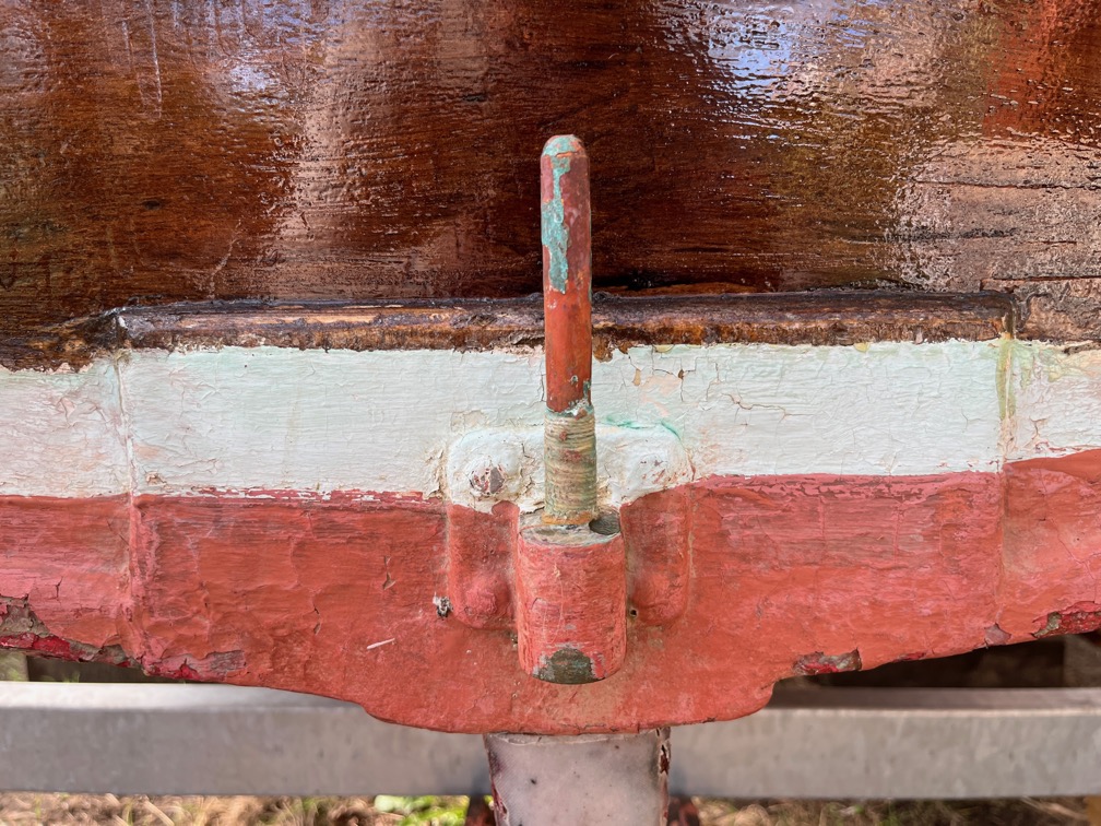
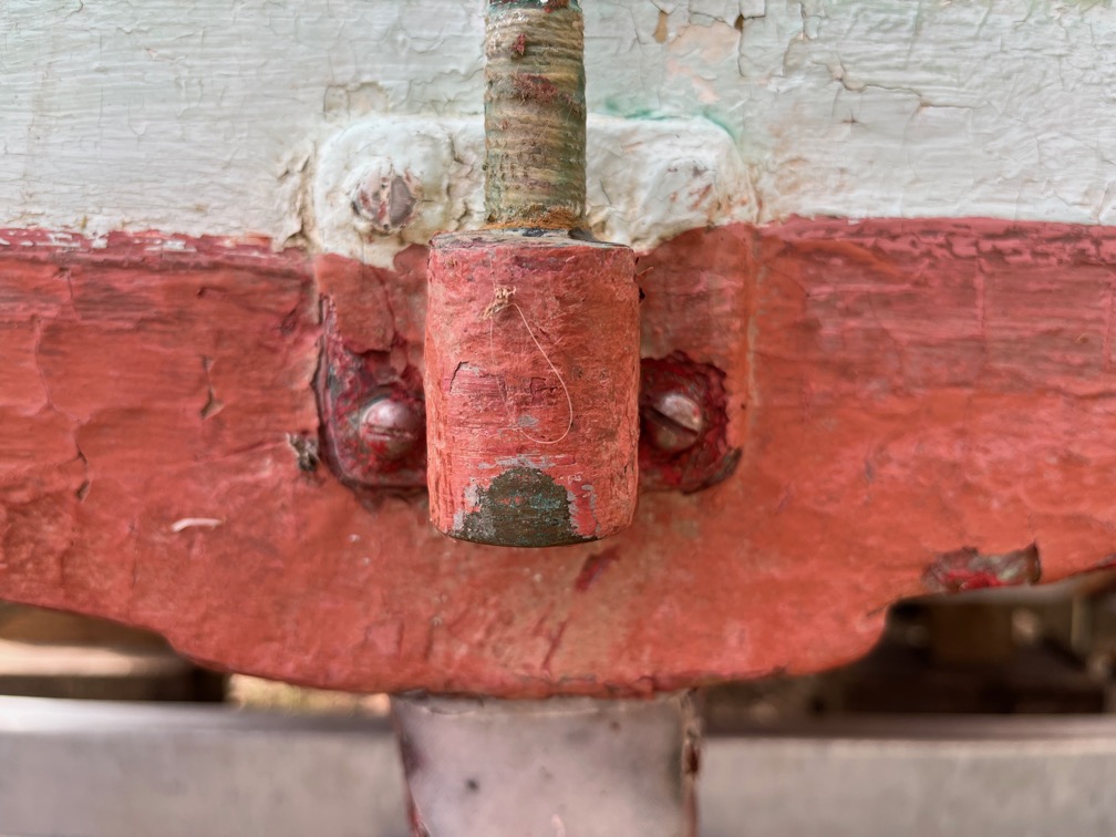
This little fitting was the reason that there was rot or water damage in the transom.

Its purpose was to guide the up and down hauls form the rudder into the cockit.

You can see it this photo on the aft deck above and to the left of the gudgeon fitting.

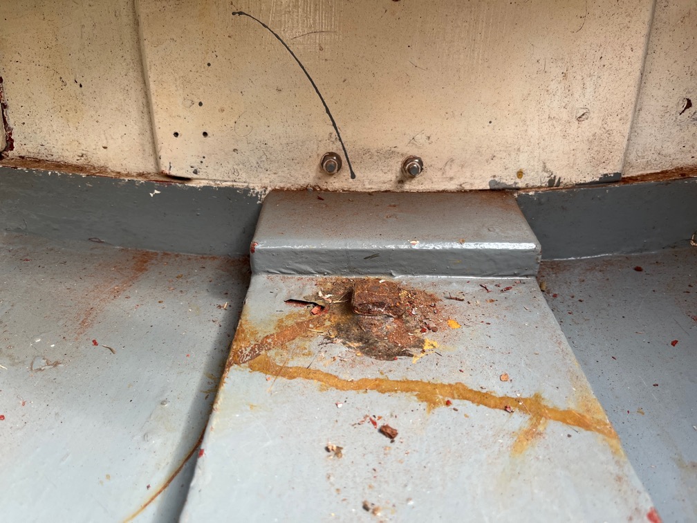
In this photo with the transom opened up, you can see where it was screwed through the deck and into the top of the transom. There is some sealant left in the wood where the screw holes was cut in half.

The problem was that despite the sealant, the two rudder lines pulled in such a way that the fitting was twisted slightly one way and then the other each time the rudder was hauled up or down. Eventually, this broke the watertight seal and allowed water, probably mainly rainwater, to seep into the wood resulting the damage you can see.

I will not be putting this fitting back. If you look in the phot prior to the one above, you can just see a groove in the rubbing strake where the uphaul has worn into the wood over the years.

What I will do instead is to nail a piece of copper over the rubbing strake where the two hauling line pass. That should stop both problems.

This is another thing that needs a little bit of attention, the aft navigation light. It was screwed to the support with steel (rusted) screws and the cable won’t go through either the hole in the back of the light, nor the hole in the deck, due to the crimp connectors. So, I shall fix both of these issues so that I can put in the deck gland.

Tomorrow !

After looking at the nav light I spent some time checking the CNC Router, cleaning it, oiling the linear bearings and so on. Nothing appears to be wrong, nothing is binding. All good news.

Time for a cup of tea.

2026-02-19 – Transom III

Varnishing first thing and I shall be very glad when all this brightwork is done !

The first task of the day, apart from the varnishing, that is, was to check that the epoxied templates, now a solid block, fitted into the transom. I am very pleased to report that it fitted without any modifications. I hadn’t trimmed the top edge as there was no point doing that if modifications were required.

The fit from the inside.

It was a simple job to trim back the tops to match the inner laminate and then give it a quick sand to smooth any rough bits.

With the graving block in place now, you can see that the tops all match the line of the underside of the deck.

This part will be out aside far a few days as the next stop on its journey is to be epoxied into place and for that, the temperature needs to rise a bit.

Next up is the gudgeon backing pad that had to be chiselled off. This is fairly straightforward, two piece of marine plywood the correct size, glued together, shaped and sanded. The only difficulty in this is that the original backing pad is half an inch thick and my two pieces of plywood measure 12 mm, nearly 1 mm thinner. Now that shouldn’t make a huge difference over the distance between the upper and lower fittings, but if it does, then I have some bronze washers that are 1 mm thick which I can put between the bronze gudgeon fitting and the backing pad.

It might be that the layers of varnish on the backing pad and the thin layer of sealant between the pad and the transom will compensate for that 1 mm difference. I shall only find out when it comes time to fit the pad and fitting.

For now, I cut the two pieces of marine plywood from some of the offcuts I have from the centerplate case sides, drilled three locating holes and glued them together. NOt epoxy this time as this pad is not structural. Why three holes and not four? With three you can’t get the pieces the wrong way round.

There are two remaining tasks to complete before the transom repair can be completed. Firstly, glue the large backing pad on the inside of the transom back together. It was cut away to allow the construction of the graving block. Secondly make the other two smaller graving pieces for the minor damage to the transom and route out the transom to accept the graving pieces.

After work I set about making the other graving pieces for the transom .

Firstly the larger of the two damaged area which was a little tricky due to the bronze fitting that impeded the router. I could have taken the fitting off, I suppose, but that was a rabbit hole down which I did not wish to fall.

Instead I used a chisel to finish off the recess.

A short while later, the graving pieces was completed and I moved on to the other area.

This time the recess was well clear of the bronze fitting, but I still had to modify the upper right corner.

And here is the graving piece for this recess.

That is all the graving pieces and recesses done for the transom. The next time Shoal Waters is out of the water for the off season, the repair that you can see in the photo will need to be removed and redone as it is virtually all giving soft returns when tapped. I’ll probably start in the middle of the upper piece and cut it away and then explore the damage from there, but I suspect that it all has to be removed.

A job for another Winter season, methinks.

One thing I need to remember to do is to make a template for the rubbing strake at the top of the transom. Or rather the bit that is missing. I can get most of it from the top of the main transom graving block but I need to extend the curve on the template to meet the strake where I’ve had to cut it away. The reason for this is that I want to laminate a new piece to fit in the gap rather than get an oversize piece and curve it top and bottom.

Finally, for today, the shaped gudgeon backing pad.

Time for a cup of tea.

2026-02-18 – Transom II

Just to give myself a change from the normal morning routine, I didn’t varnish the brightwork until this afternoon. Translation, I overslept and didn’t have any time before starting work !

Nevertheless, these items did get a coat of varnish but on the reverse side to the sides coats before. These all have four new coats of varnish on the first side and I’ll do four on this side as well.

I checked the new bolt length for fit on the centerplate case sides and there is plenty of length now.

The next task was to get the laminates for the transom repair made, starting with the outermost. As this is the face that will be seen, it needs to be as perfect as possible. Grain going in the same direction as the wood surrounding it and with as few gaps around the edges as possible. This is not difficult, it just requires a bit of to and fro as you dial the size in to fit exactly. I normally cut the piece about 1mm too large, offer it up the the gap and cut off fractions until it fits exactly.

What I did not do was the same thing for the top edge. I made the sides fit, as you can see, but left the rest too large. This will be fitted later when the inner laminate is done and the three pieces glued together.

Time for a cup of tea.
After work I set about making the other two laminates for the transom repair.

This is the inner laminate and like the outer one, the top edge was not finished.

And this is the inner laminate.

This one wasn’t quite such a good fit, but this will be filled with thickened epoxy when the plug is glued in place.

I traced the curve of the underside of the deck on the inner laminate. It is quite rough so I decided to smooth it out.

I clamped a flexible batten to the wood such that the edge ran along the pencilled line, more or less and then drew a dark pencil line along the batten.

Now the curve is fair and I can cut it out.

The result looks lopsided and that is because it is. The repair is not quite centred on the transom, so the curve is not symmetrical.

But, as you can see, it is a pretty good fit.

All that remained was to locate the laminates and I did this by drilling four 3.2 mm holes in the inner laminate, putting all the laminates in place and drilling through the holes right through the inner laminate and halfway through the outer such that the holes did not appear on the outside of the outer face.

Short piece of bamboo skewer were inserted into the holes to hold the laminates in position. This was dry fit to check that I hadn’t messed it up and then the laminates were brought inside to warm up.

Once the laminates had warmed up it was time to epoxy them together.

Neat epoxy was spread on all the surfaces to be glued and left for a few minutes to soak in a little before the laminates were assembled, using the bamboo skewer pieces to locate the three in the correct relative positions. Lead weight was used to apply clamping pressure and the excess squeeze out removed every quarter of an hour or so the avoid having to deal with hardened epoxy later on.

With the weather due to warm up into the low teens at the weekend, this plug will be ready to be glued into place when a suitable temperature is reached.

All in all, a satisfactory day’s work.

Time for a cup of tea.
2026-02-17 – Transom Major Issue

After I had lunch I still had some time left on my lunch break, so I decided to cut out the top section of the transom that was damaged and giving soft returns when tapped.

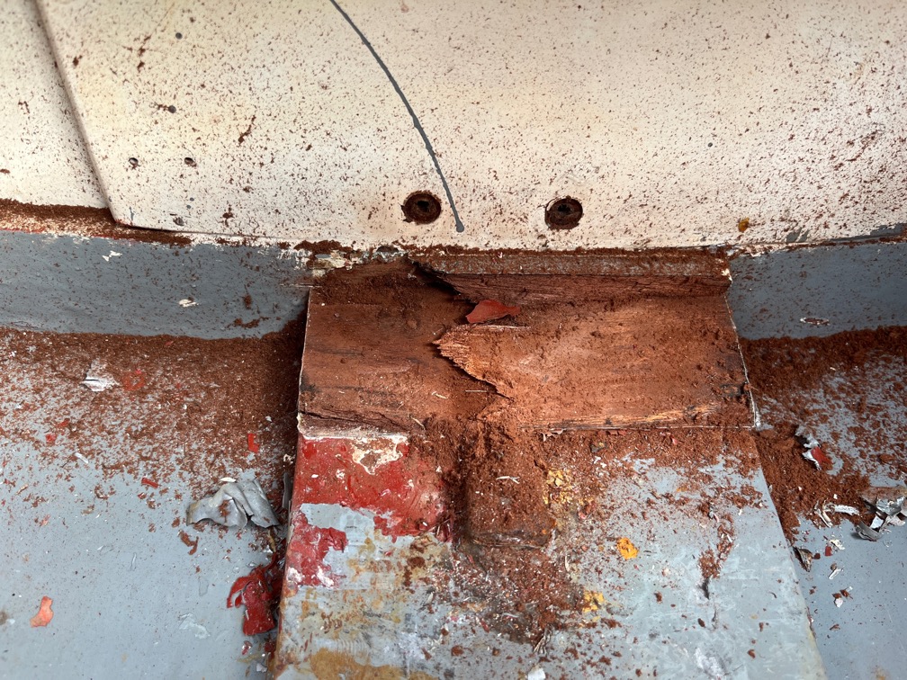
I was surprised to find that the damage was quite extensive.You can see the area that was marked as needing a graving piece, I’ve had to cut entirely through the transom. You can also see that the rotten/damaged wood extends into the aft deck and down behind the backing pad upon which the rudder gudgeon was fixed. That meant that the pad had to come off and in the process of removing the rudder fitting I found that only the lower two screws were holding. The upper two came out without needing to unscrew them.

So, that part of the transom has to be replaced and the reason for that is that if nothing was done and the top part of the rudder broke away from the transom due to the rot behind it, you would be unable to control the boat and that is a safety issue.

I went back to work at this point and continued at my next break.

From this point I have to chase the rot along the deck and the transom to find good wood before I can rebuild the transom.

This is how much needed to be removed of the transom before I found good wood. The deck was also cut back a little but not that far. The rot seems to have travelled downwards.

I have no idea what this feature is, it was filled in with epoxy but you can see that it was painted at some point and may have been an old repair made by cutting out the ‘scoop’ of wood and then sealing and painting it.

On the other side I had to take the beading at the top of the transom back a little further than the plywood./

This is the centre section and I think that the pad of wood glued to the transom from the inside is either a backing pad to spread the strain of the rudder or a repair. Possibly even both.

Still, this now needs to be dealt with.

The repair is not difficult despite looking quite extreme. I’ll cut a plywood router guide and nail that to the transom about 5mm out from the hole and then use a router follower bit to make the edges of the hole square to the face of the transom and square to the sides and bottom of the hole. Then I shall make another plywood template that cuts a hole about 10 mm wider and taller than the hole and remove two thirds of the thickness of the edges of the hole. I’ll repeat this once more such that the edges of the hole are stepped instead of straight. The hole will then be filled with three layers of plywood with each piece filling one of the steps.

I’ll need to remove the big pad on the inside and the batten that runs at the top of the transom since the glueing is done from the outside inwards and those will get in the way. A portion of the aft deck will be removed so that I can graft in a new section once the transom is done.

If all goes well, this should only take a few days to repair.

Time for a cup of tea.
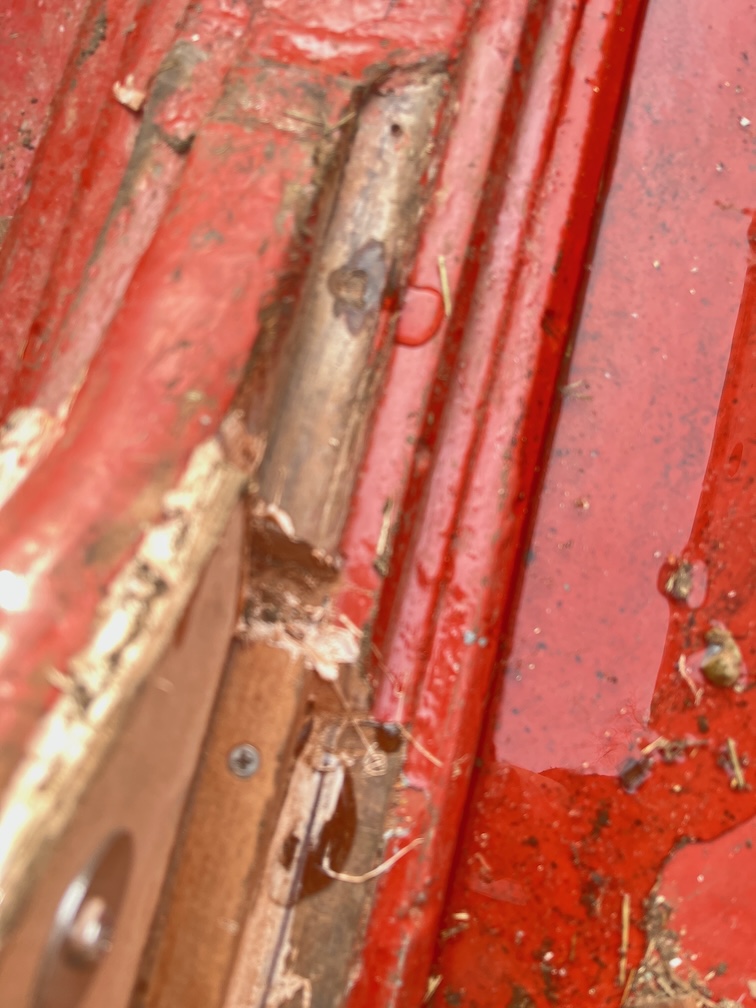
The first thing to do is to cut away the sections of the transom that will impede the router. I decided not to remove the centre backing pad as I do not know how it is fastened on at the back and this way is quicker.

The second thing to do is to make a template for the curvature of the top of the transom since all the filler pieces will need to follow this curve or the deck will not sit flush with the top of the transom when it is repaired.

The transom is three quarters of an inch thick or a fraction over 19 mm. The marine plywood I have is 6 mm so three layers of that plus epoxy will be around that thickness. All well and good.

Time for a cup of tea.
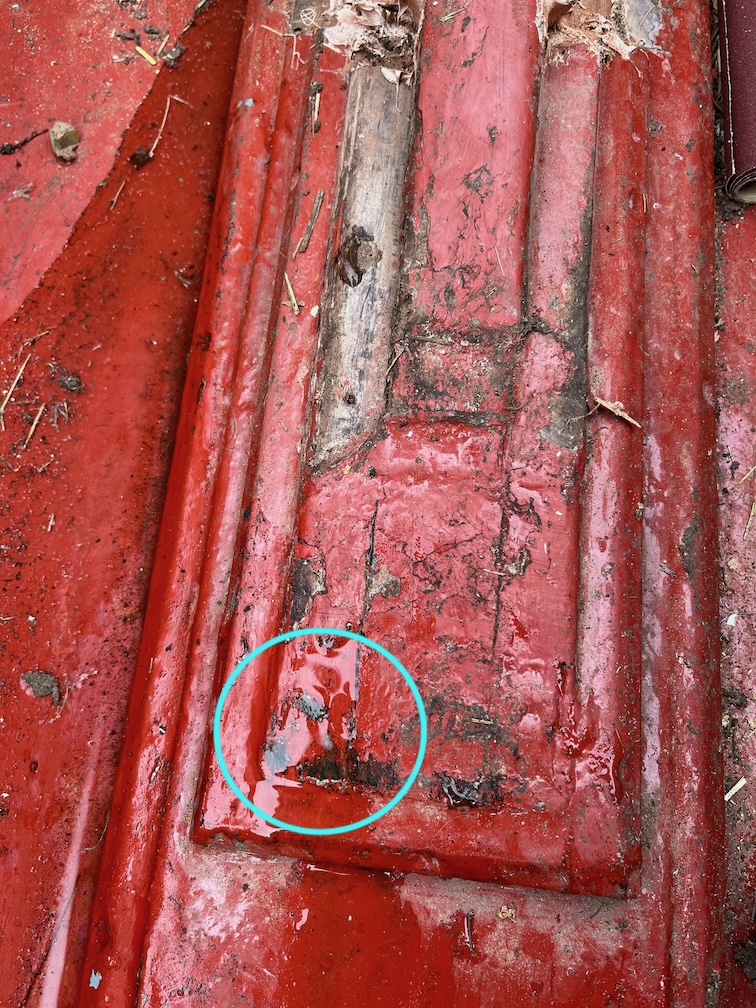
After knocking off from work I set about cutting the stepped opening.

Firstly the curved template. This was fairly easy to do, I just pressed a piece of cardboard on the outside and drew under the aft deck on the inside and cut along the line. Easy.

This is the routing template. It is quite large since the cut out gets bigger each time it is used. This will straighten the edge of the current raggedy hole.

And this is how it is used. The template is nailed to the transom with panel pins and a bottom follower bit in a trim router is used to cut away the excess wood all the way through the transom.

Here is the result of the first pass, nice straight edges.

The only drawback of this method is the rounded corners. The top ones can be cut away with a sharp chisel easily enough, but the bottom ones are a sufficient trial that I round the corners of the inserts instead.

This is the result after three passes, each one larger than the last but a shallower cut.

This is a slightly better view. I checked with a piece of plywood and the two outer cuts are about as perfect as I’m going to get. The inner cut is 1mm deeper than the plywood as three layers of 6mm is 18mm and the original transom is 19 mm so there always was going to be a discrepancy, but I can live with that.

That’s it for today, it’s dark and cold.

Time for a cup of tea.
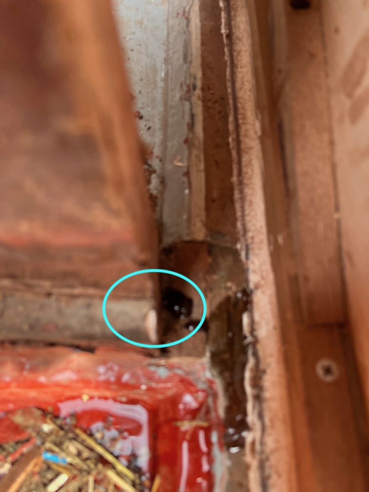
2026-02-17 – Transom I

After the usual round of applying varnish to various parts of the boat, I took a look at the case side.

Here I have removed the peel ply and the result is pretty good. It will need sanding but that was expected. For now, I shall put it by the Rayburn to keep warm to allow the epoxy to reach full strength before I take sand paper to it.

After that I turned my attention to the transom. Armed with hot air gun and a scraper it was the work of only half an hour to remove the paint and varnish. I say paint, but I think it is a coloured varnish rather than a paint and you can see why it was put on. There are several damaged areas as well as dark areas where the wood has suffered water damage.

This is an area that needs some attention, at the top of the transom just to the left of the rudder gudgeon. Here is looks as though the plywood has been sanded too aggressively and that has removed the outer layer of the plywood. The exposed and rough grain will wick water easily and although no damaged seems to have occurred as yet, this area needs to be sealed to prevent water ingress.

This was the most surprising area. It looks to be a massive repair and I suspect that it was carried out due to severe water damage.

This is a section from a photo of Shoal Waters whilst she was still in the ownership of Charles Stock and you can see a large discoloured area to the left of the name board that corresponds to the repair in the photo I took this morning.

So, more tasks to add to the list. Remove any remaining varish, sand and fill the two, possibly three areas that need graving pieces. Carry out some stain removal to at least lighten the darkened wood. Then I will probably stain the entire transom just to stop it looking such a light colour and after that, we shall see.

Sa far an interesting morning.

Time for a cup of tea.

During my next break I sanded the transom with 180 grit sandpaper and then went tapping around to see where the soft returns were.

The green area is where I’ll certainly put a graving piece and the red areas show where I’m getting soft returns with my tapping. The top red area is a place where I’m tempted to put another graving piece rather than use the epoxy sealer. One or two of the very darkened areas of wood I’ll treat with Oxalic acid and try to bleach the wood a little, but other than that I think the transom will be lightly stained to even out the discolouring and then varnished. This will not hide the repairs and such, but they will be less noticable unlike with the varnish/paint which hid everything.

The two red area on the left will be left until Shoal Waters is next out of the water for maintenance and I can spend more time investigating and repairing.

Time for a cup of tea.

2026-02-16 – Centerplate Case II and Small Tasks

The weather this morning was a little warmer than yesterday, but even so, the day started in much the same fashion as previous days, varnishing.

The first small task was to insulate the flame spreader handle. This handle is not left on the spreader when in use but used to remove the spreader when hot. Unfortunately, the bare handle becomes very hot very quickly and without care a burnt hand results. This insulation consists of 6 mm round stove rope threaded onto the handle, glued at the ends with seal adhesive and then, when the adhesive had dried, cotton string was wound over the stove rope creating the handle you see. This resists burning and insulates the handle well enough to be able to use it on a hot spreader without burning skin in the process.

The spreader fits well on the galley stove but I now need to find somewhere to stow the spreader and handle.

The next task was to repair the port centerplate case side that was damaged yesterday. I have clamped a small batten of wood encased in film up agains the edge where the repair is required.

Epoxy lightly thickened with low-density filler was dripped into the damages area and peel ply applied. I used the fast hardener as it was a simple application and I did not need the extended pot life of hte slow hardener.

There were also two other spots where the glass mat was slightly exposed and were treated similarly. Once the epoxy has cured all three areas will be lightly sanded to the same level as the surrounding epoxy.

Another small task was to rummage through the various boat bits I have around the places for two cleats to put on the boom for the luff reefing lines. I did have some but they were far too small for the job, so suitable ones are on order.

To complete the galley stove locker I put in place some chafe and clink prevention.

I put a length of sticky-back neoprene tape on the bottom of the locker where the edge of the stove board or the lid will rest. This is the chafe protection.

Then I used some very sticky double sided sticking tape to fix a small foam paint roller in the corner of the locker and this is the clink protection.

When the stove is stowed the foam roller prevents the lid of the stove opening and closing, going clink against the locker or against the stove itself every time the boat rocks with a wave. I know this from experience of living aboard a sailing boat for ten years. There’s absolutely nothing so annoying as something going clink, clink, clink, clink whilst you are trying to sleep. Whether it be pots, pans, crockery, loose tools, it doesn’t matter, it is infuriating !!!

Anyway, that completes the galley stove and locker task.

The next small task is to remove the Maldon sign on the transom.

This is the back of the sign and you can see that some of the transom has pulled off with the sign. This sign is marine plywood and was glued in place with a sealer adhesive and a very good one at that.Too good, as it turns out.

Here you can see the area on the transom that was pulled off. You’ll note that there appears to be three holes in the transom, two at the bottom and one at the top right. I would presume that there is fourth under the white stuff. Armed with a heat gun and scraper I got rid of all the sealant and the brown paint/varnish.

Here is the result. there was indeed a fourth hole but it also looks like that large area of white sealant also filled in an area that was damaged. You can see the vertical grain of the plywood that is under the outer layer, so there seems to have been some older damage to the transom in this area.

I recall that for the first year that Tony Smith owned Shoal Waters, he mounted what looks like a long shaft seagull outboard motor in the stern and I wonder if these holes and damage were something to do with that. Not that it matters, the thing is how far down the rabbit hole do I want to go with the repair? The simplest and easiest way to deal with this is to fill it with sealant again, a non-adhesive type, since it is under the Maldon sign and will not be noticeable. The correct way to fix this is to insert a graving piece by cutting a shallow recess where the damage is now, I’d make this 6 mm deep as that is the thickness of the marine plywood I have, then cut out a piece of plywood that fits into the recess and glue it in.

My first inclination is to do it properly, but I recall that there is a soft area on the transom on the port side that needs looking at, so I am really tempted to scrape the layers of paint and varnish off the transom entirely, it comes off really easily, and to see if there are other areas that need to be dealt with and do them all at once.

Something to think about.

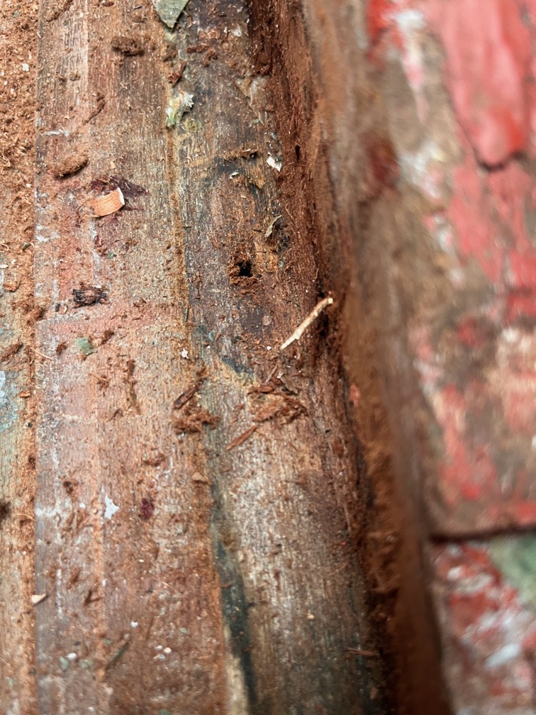
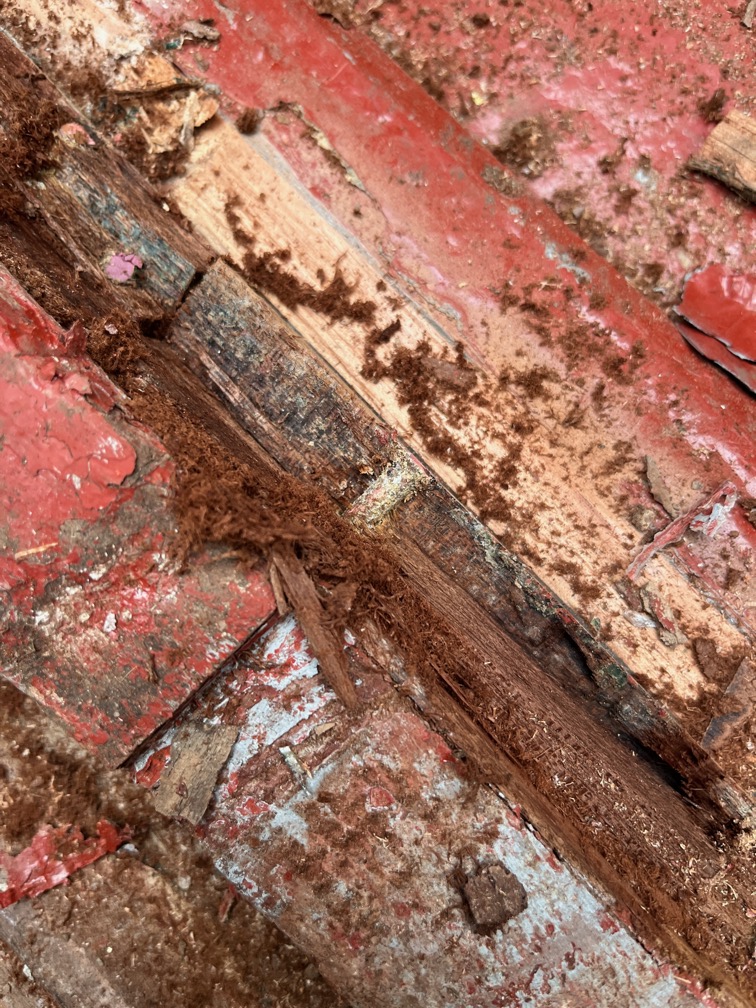
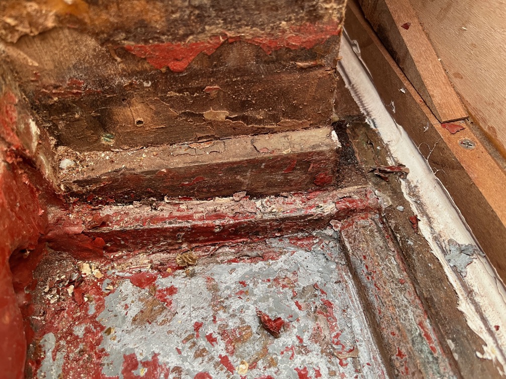
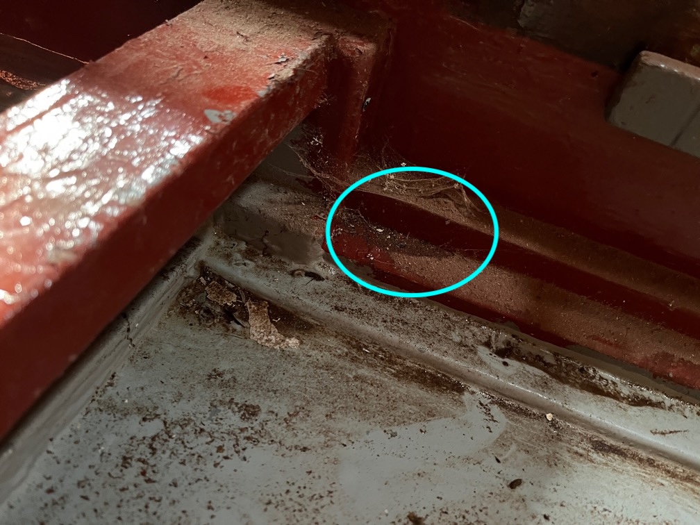
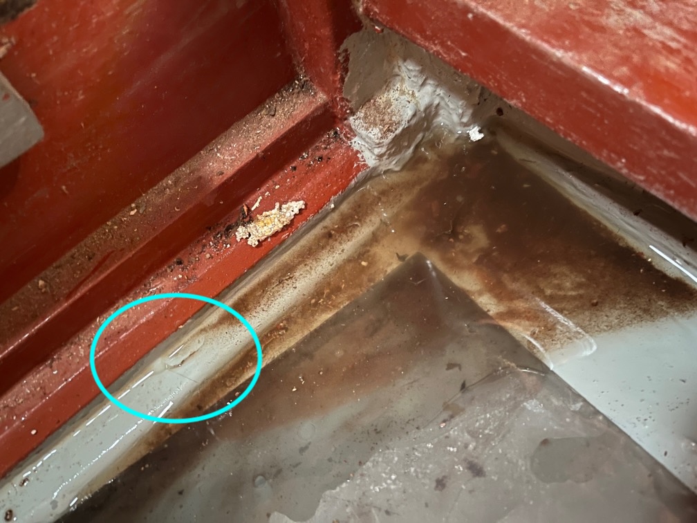
The final task for the day, for which I do not have photos, was to clean up the slot and top of the keel. Mostly this meant removing any loose glue by sanding and then prising it off with a chisel. Quite a lot is on very securely and rather than risk damaging the wood by forcing it off, I’m going to leave it on. The sides of the entire slot was sanded with 120 grit sandpaper as was the top of the slot. I also cleaned up the front face of the aft block and found another soft spot. This was about the size of the thimble and I excavated it with a chisel blade. Before I assemble the case properly this area, as well as the two soft spots on the hull, will be liberally coated with the penetrating epoxy. The thimble sized hole itself will then be filled with thickened epoxy.

Time for a cup of tea.
2026-02-15 – Centerplate Case I

It is a miserable day today, here in the Fens of Norfolk. It has been sleeting sideways for the last couple of hours and it cold, just 2º C. Still, most of the tasks for today are in the workshop out of the wind and rain.

First up is the name board.

This is the board vanished on the front..

But not on the back. The varnish you can see here has come from being varnished in place on the transom. The trouble is that having no varnish on the back has caused the wood to warp and with screws in the middle of the sides instead of on the four corners, the warp has pulled the top and bottom away from the transom and varnish has seeped down behind the sign.

So, to carve the name I had to first un-warp the board. It’s currently resting on the Rayburn, varnish side up and is starting to get flatter.

Next I took sandpaper and scraper to the rudder stock for a little energetic work to warm me up.

Next, trimming the excess glass mat and epoxy from the case sides. This one worked well.

The port side not so well. The trimming and sanding around three of the edges came out correctly.

But I screwed up when putting the peel ply on the aft section here and it overlapped the inside face where it should not and I had to cut away the glass matt to get it all out. It’s not too much of a problem, I’ll just have to mix up some epoxy and patch the gap.

In the meantime, I drilled out the pivot bolt holes, put the case sides together inner face to inner face, put the metal plates on the stiffeners and put the bolt in place with the spacer on the outside. As you can see, the bolt is about 5mm too short ! It has to be long enough to screw through the nylon locking ring, it is not called nyloc for nothing, or be long enough to allow a lock nut.

So, one 10mm longer is on order. This one will do for the next phases, the dry fit possibly even the real fitting, but the longer one will be needed before the boat goes into the water. There will be six layers of sealant, two either side of the spacer and one each under the metal plates and one on the outside of each plate and under the bolt head on one side and the nut on the other. All those sealant layers will probably mean that the shorter bolt may not fit. I have M10 studding from which I can cut a longer bolt but since it is mild steel it will only be good enough for the assembly.

Still, not having the correct bolt will not stop progress.

It has stopped sleeting and is now snowing. Still cold.

Makes one glad for a workshop.

Since I have the poop deck removed I decided to continue the theme of getting ahead of the brightwork where possible and give it a coat or two. I was sanded in the workshop, brushed off and then brought into the workroom for its first coat of varnish. Being an outside piece of varnish it needed a good sanding but has come up nicely as a result. This might only need two coats. I might put more on, after all it is going to be out in all weathers when sailing and under a piece of canvas when on the mooring, so more coats of varnish will be better than less.

One of the things on my list of upgrades for Shoal Waters in the future is to replace all her old blocks with new ones. In the meantime I will replace the old blocks with Tufnol blocks that I have left over from building Naiad.

Shoal Waters’ blocks are currently like the one on the left and the spare ones I have are the others. I say spare but the fact of the matter is that I ordered exactly enough blocks to dress Naiad’s mast, the five new looking blocks on the top row. But they didn’t arrive. After a month or so I got back to the supplier and asked what had happened and they had no record of the order being fulfilled, so they sent out a new set of blocks which arrived within a few days. All well and good. Naiad was launched and I thought nothing more about it until about nine months later when the original set of blocks arrived in the post.

I contacted the supplier and they said that since they still didn’t have a record of those being fulfilled and dispatched I was free to keep them. They have been sitting in my rigging kit box for the last seven years!

So, Shoal Waters will have her existing block replaced by these Tufnol blocks and I’ll make some shiny new wooden ones for another season.

For now, since it is Sunday and I have already carried out a number of tasks, I shall call it a day and rest for the remainder of the afternoon and evenong.

Time for a cup of tea.
2026-02-14 – Aft Lockers

A slight change to the procedure today, it was 1º C when I first went down to the boat this morning and there’s no way that it is suitable to apply varnish. So I turned on the heater and took a look at the work I did yesterday.
Having removed the cramps and such I tested the epoxy with a fingernail and found that it was quite solid. It seems that the heater arrangement worked well.

I trimmed off the tops of the pins and the did not break the top off the block, so I will presume for the moment that it is well stuck.

Time to clear the area for the next task.

This is the area under the poop deck and you can see the lockers that occupy the space under the aft deck. This is pretty useless as is in order to get at anything in these lockers you need to clear out everything under the poop deck, or remove the poop deck.

I would have left these untouched but the surveyor noted:

…the two bronze cleats aft are only screw fastened to the thin plywood deck; without any wooden blockings below. Recommendations: Ensure the aft bronze mooring cleats are securely mounted.

The access to these cleats is via the locakers and that is not going to be easy. So, I elected to remove these lockers which will not only allow backing pads to be placed under the cleats but easier access to the otherwise awkward space.

The area under the poop and aft decks is quite spacious.

There is even more space once the locker fronts are removed. This space is now usable.

The next part of the task is to remove the cleats. This one has a wellie hook.

Here’s what Charles has to say about wellington boots:

I use traditional knee length wellington boots for mud work. They need to fit well so that they do not stay behind in the mud as you walk forward. One minor irritation, especially for knock-kneed sailors is that mud on the inner side of each boot will transfer from one boot to the other as you walk, rising higher each time and getting onto the inner side of your trouser legs above knee level. This means mud on board and in the cabin. The answer is to walk slightly ‘Frankenstein’ fashion, preventing the boots from touching. Whatever you do when working in mud, some will stick to your clothing. Do not try to rub if off wet for it will only stick harder. Leave it to dry when it will brush off cleanly. Once boots have been in the mud they are not welcome on board until cleaned, but this cannot be done without water. Don’t leave them stuck in the mud alongside the boat for they will float off very quickly as the tide returns. Tie them to a cleat (see fig. 5). I use a piece of shock cord with hooks at each end. Once wellingtons came with holes punched in them at the back just below the lip, presumably to tie them together in pairs. Since the advent of packaging in hygienic boxes such holes are missing but the office punch will suffice.

Sailing Just for Fun pp 57-58

Anyway, the hook is in the way and needs to come off.

The screws in this cleat have been replaced with stainless steel screws, a sure sign that the originals were brass and dezinced to the point of being useless.

The screws came out easily, thankfully, which is not surprising when you consider that they are just into 3/8″ plywood.

Similarly, the screws came out easily on the port side. Now to make the backing pads.

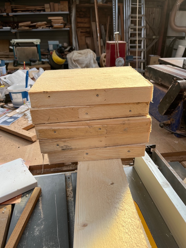
I cut the removed fronts of the aft lockers into four 120mm square pieces…

…and glued them together with the varnished side outwards.

It was still sufficiently cold to make the glue drying time long, so into the house they went to be placed on the Rayburn with a pot on top as a weight.

Since I hd a little bit of time I decided to try and locate the ‘soft return’ that was reported by the surveyor on the port bow.

This is it here, I think. Here’s a short video of me tapping.

I think you can hear the difference in the sound return from the good and soft wood.

I’ve sanded the paint a bit to tidy up the area and once the wood has dried I’ll apply so of that penetrating epoxy I keep going on about. The same for the transom, if I can find the soft spots.

The name plate on the stern is looking a bit ragged so I took it off and sanded and scraped a bit. The trouble is that the letters are a vinyl transfer, as far as I can see and sanding is going to sand off the vinyl as well.

You can see that happening on the bottom of the ‘W’.

Time to move on with the cleat backing pads. It was a bit tricky but eventually I got the bolts cut to length, the butyl tape applied and the backing pads in place. This is the starboard one…

And this is the port side. The bolts came out very close to the edge of the pad, but that is due to the location of the cleat on the deck.

The starboard cleat from the top. The squeezed out butyl will be removed later.

The port side cleat had a bit more butyl tape under the cleat so there is more oozing out.

The drop nose pin arrived in the post this afternoon and I didn’t waste any time trying it out.

The is the other side and the head has a groove running around the circumference for attaching a light line.

The tiller was a tight fit, mostly due to excessive build up of varnish, so I took it over to the belt sander and slimmed it down a little.

I had to take more off than required as needed to varnish the now bare wood.

This does seem to be a very nice piece of wood and as far as I can tell, it is the original tiller that Charles put into Shoal Waters back in 1963. Every photo I have of the boat around that time shows this as the tiller. I wonder if this came from Charles’ previous boat the Zephyr? I know he took a lot of the gear out of the Zephyr and used it in Shoal Waters, but whether the tiller was part of that I don’t know.

Still, it is at least 63 years old and in near perfect condition.

Hanging from the beams in the workroom with a coat of varnish. I lightly sanded the existing varnish prior to applying fresh.

I also washed these two boards with white spirit, lightly sanded and applied varnish. The board on the left is the bottom washboard, and the other is the board that goes between the two thwarts under the poop deck. A second coat of varnish was applied in the cabin, so that is also coming along.

It was a great day. The sun shone and despite a cold start to the day it soon warmed up to a balmy 7º C. There was little or no wind and I managed to get a lot of things done and ticked off the list.

All that remains of the major construction efforts are the fitting of the centerplate case and whilst that is not a simple task, it is not difficult. It is, however, just a tad daunting. Making it completely watertight and strong is critical to not having the boat sink when launched !

Time for a cup of tea.