The forecast temperature for today was 11º Celsius, quite a difference from the -10º Celsius we had a week ago, but the warm spell is just forecast to last two days and I determined to get some of the exterior epoxy work done. I took multiple tea breaks and got to work.
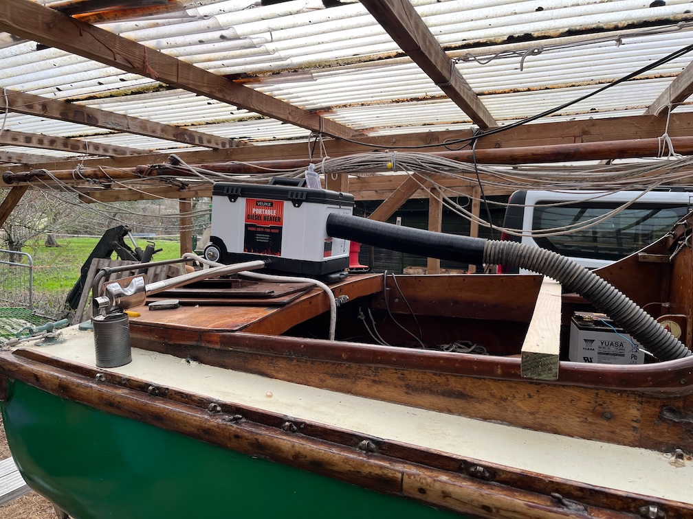
The first thing I did when I saw the forecast on Saturday was to buy this portable diesel heater which was delivered yesterday. The idea is to pump warm air into the cabin and thereby heat up the decking and coachroof from underneath. Hopefully this will allow the epoxy on the outside to cure in a reasonable time. The heater will be used for other purposes, but I bought it sooner than I expected for this job.
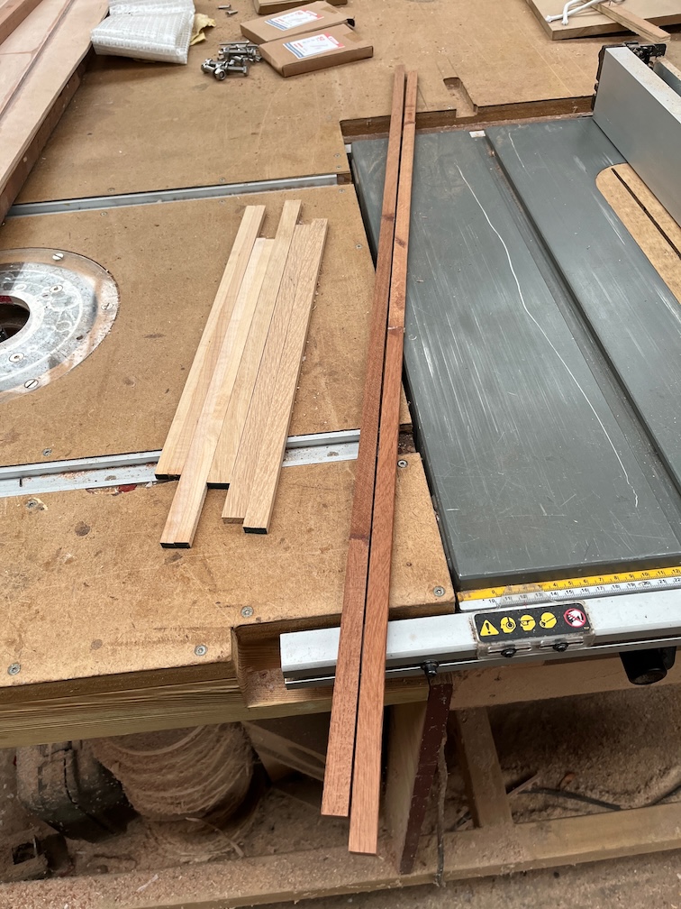
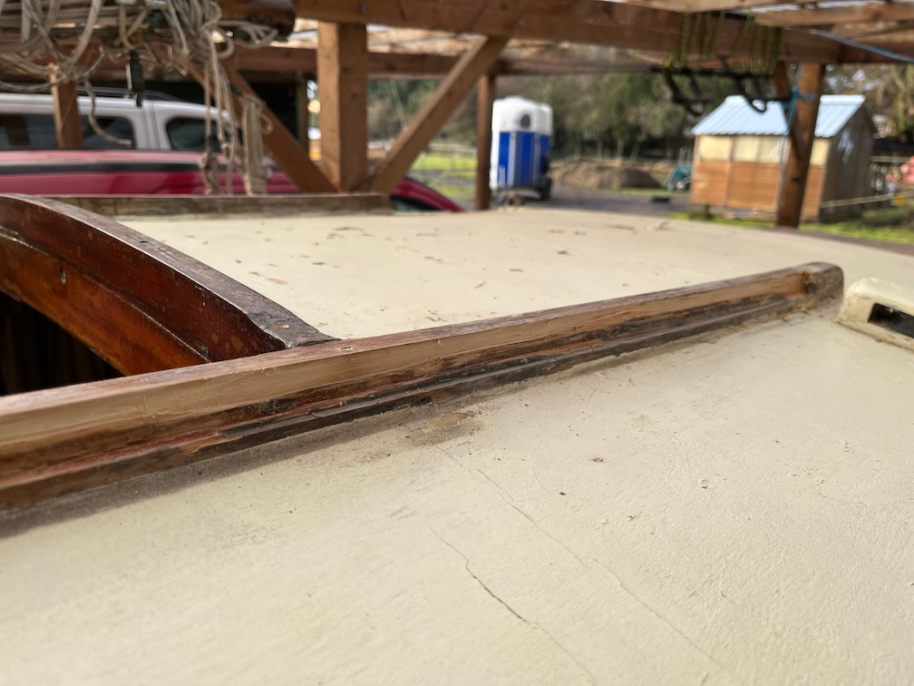
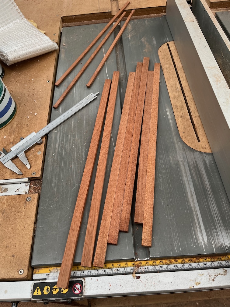
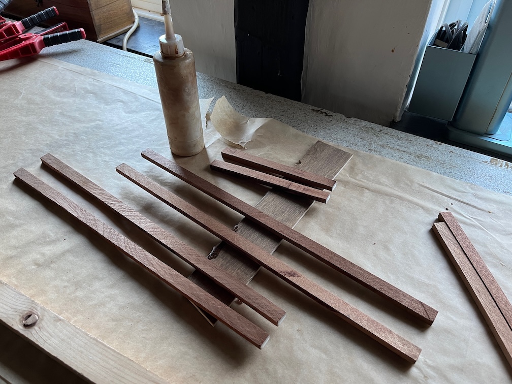
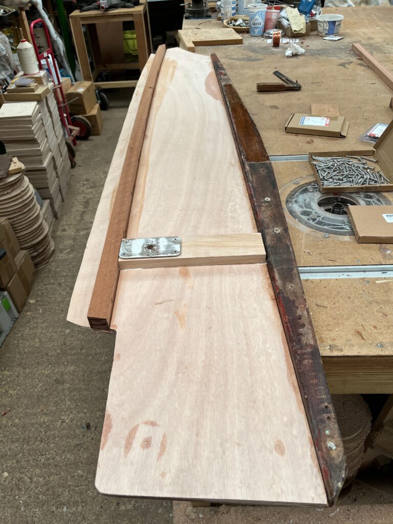
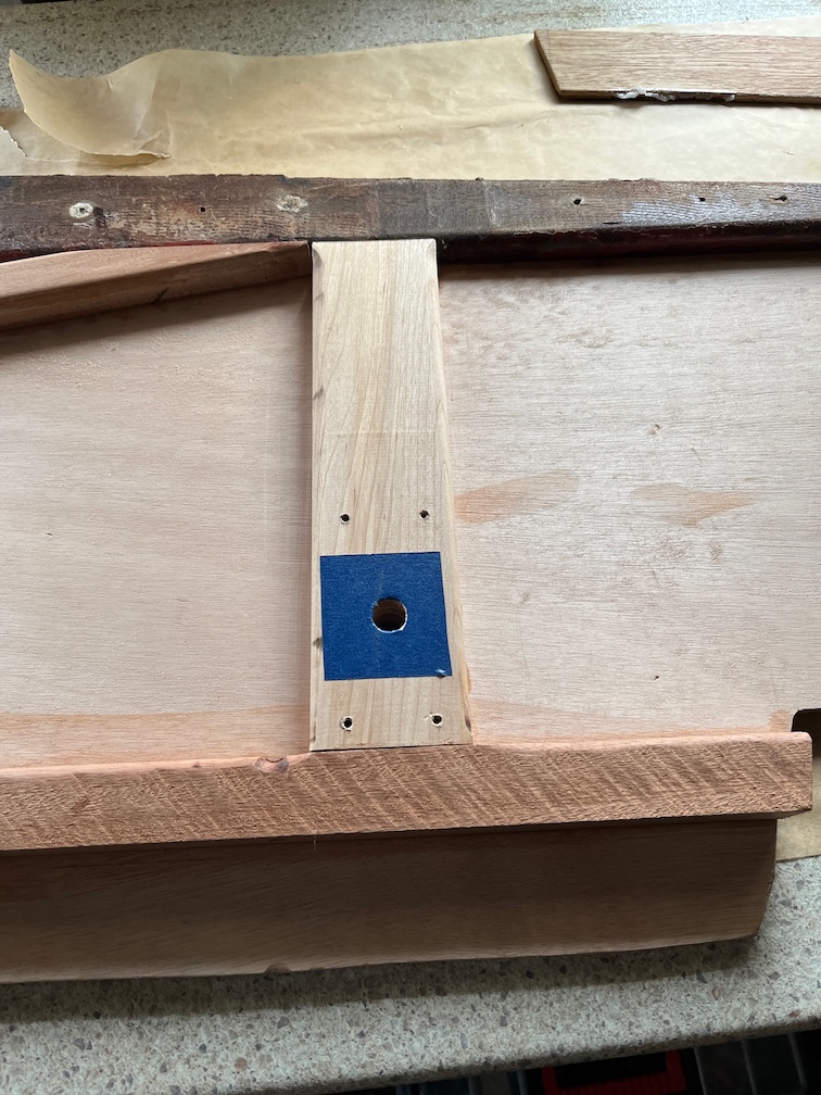
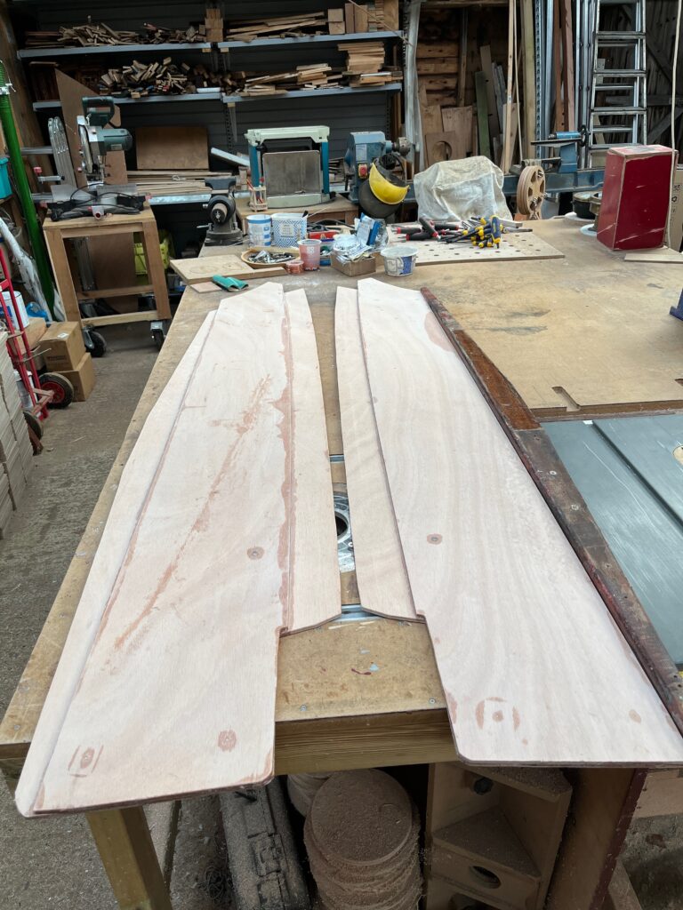
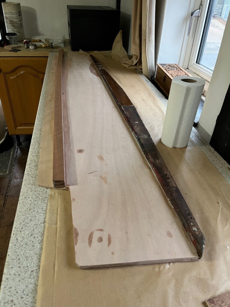
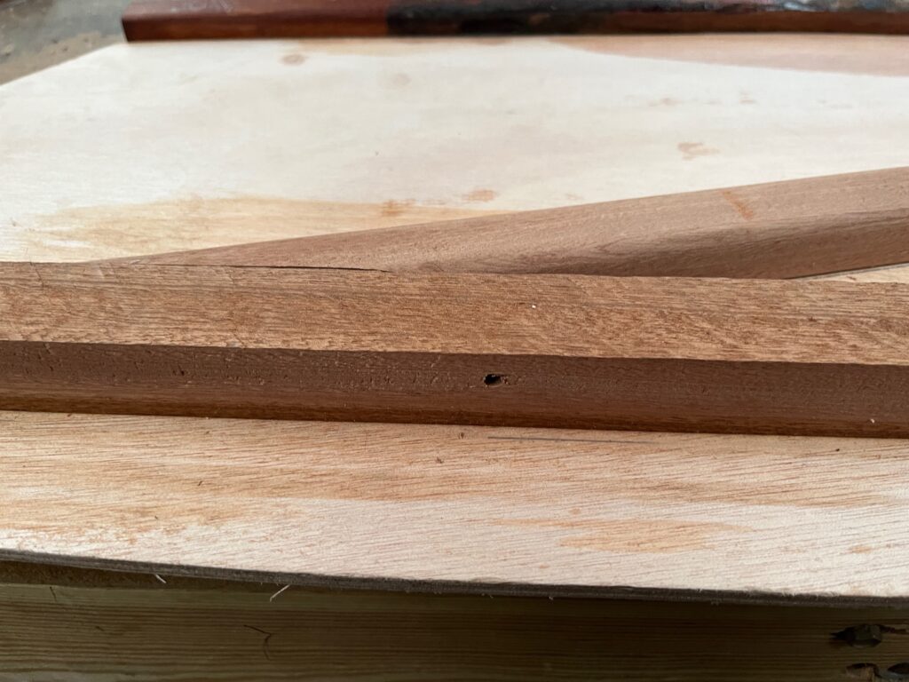
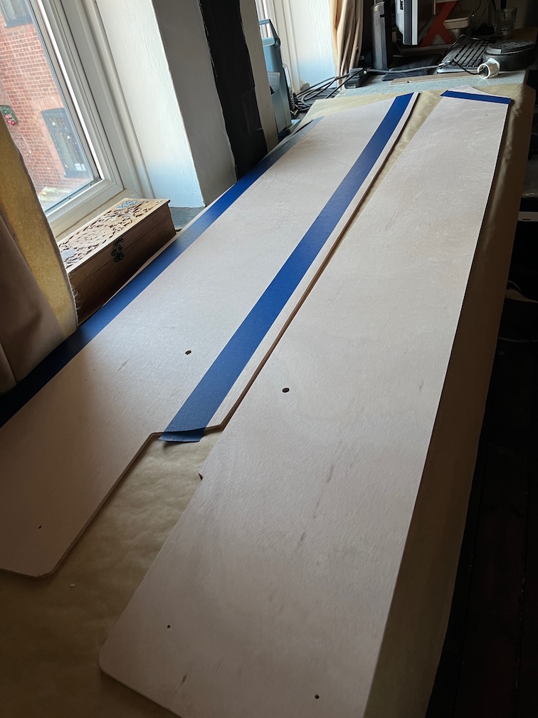
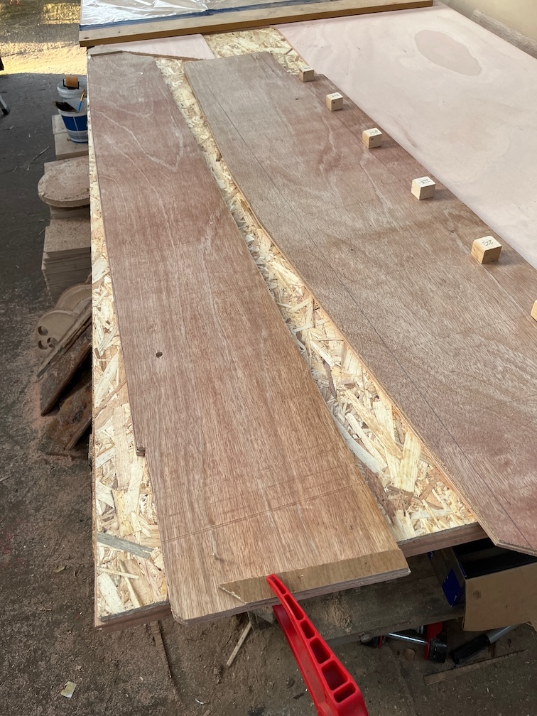
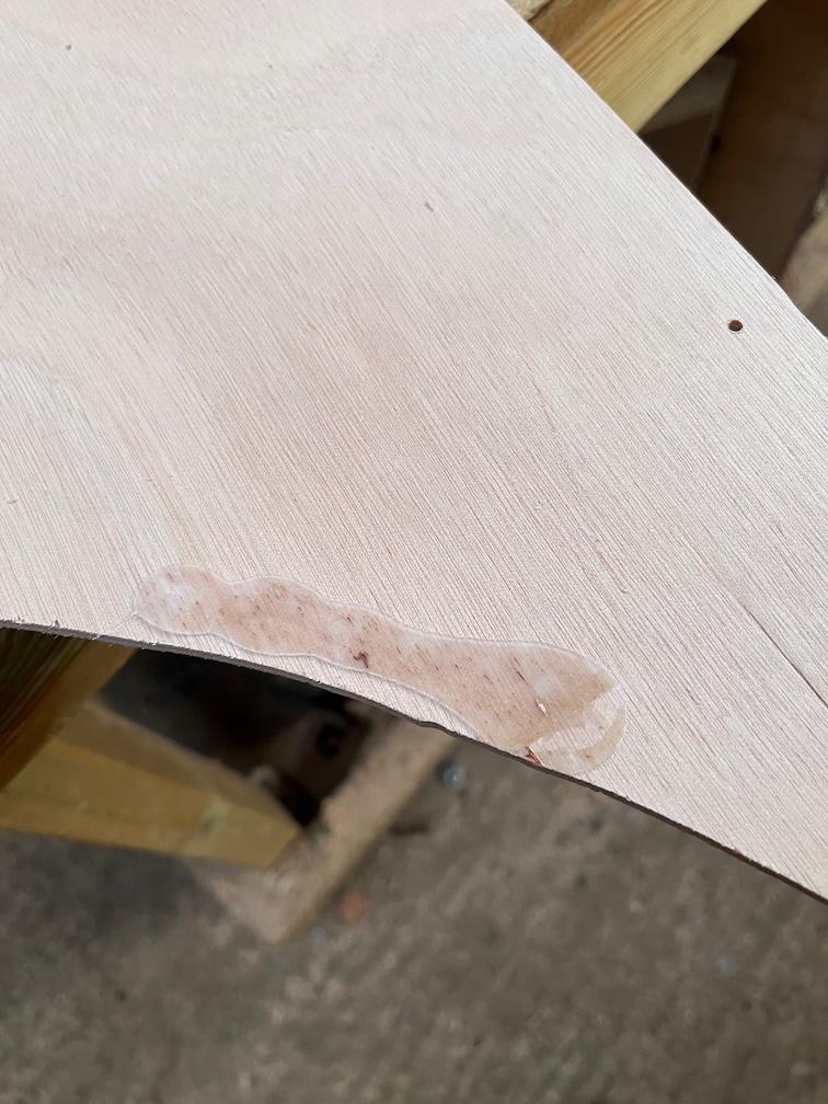
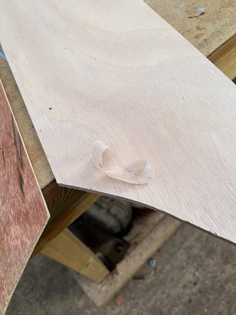
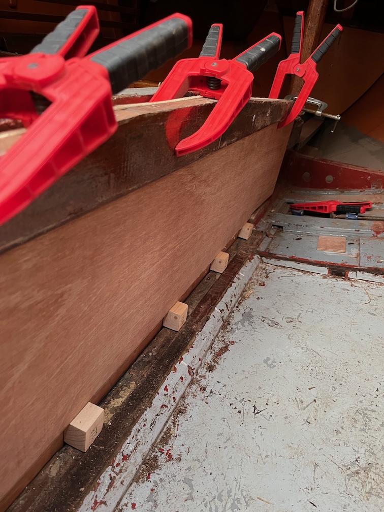
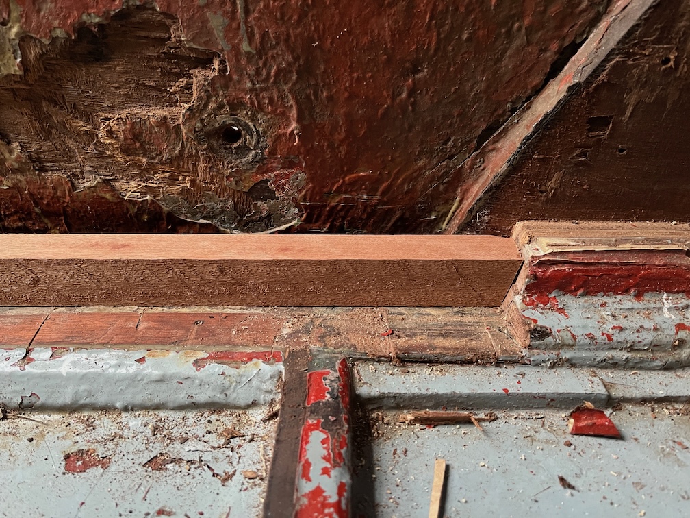
Then it was on with the epoxy. These are the new runner pieces with some spacers that were used to make sure that the slot itself is at least the correct size.
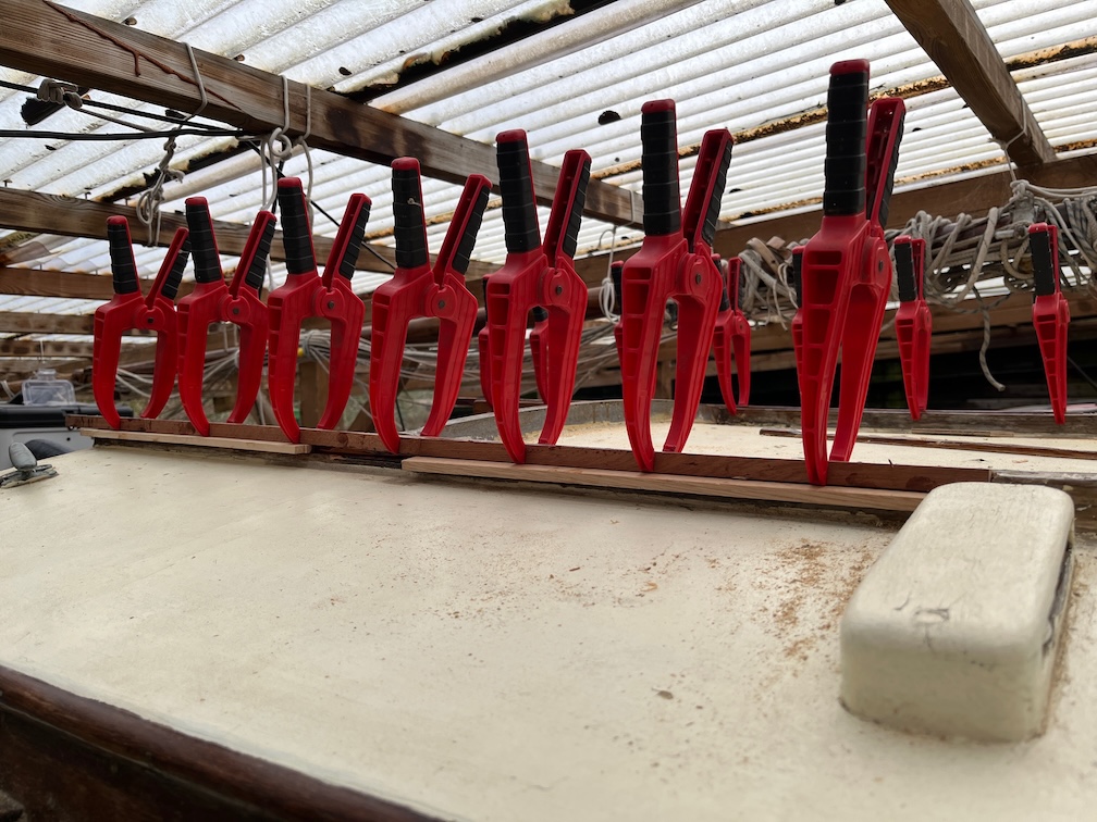
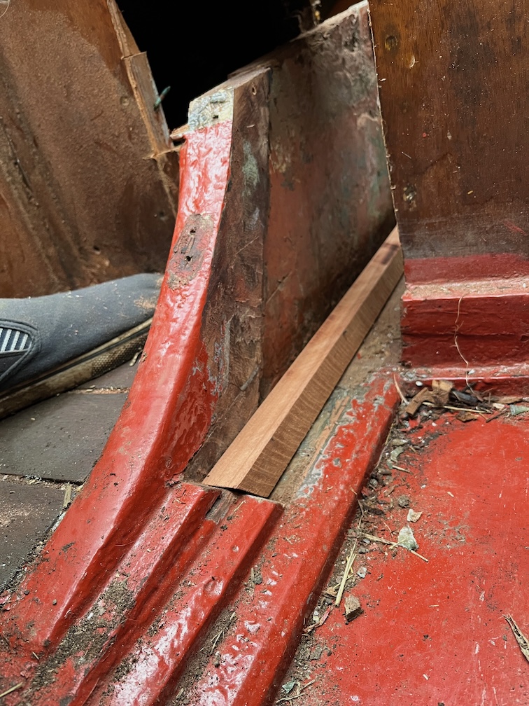
It took some time but this is the result. For this part of the repairs I used the fast hardener as the temperature is reduced, rather than the slow hardener I’ve been using to give me a longer pot life.
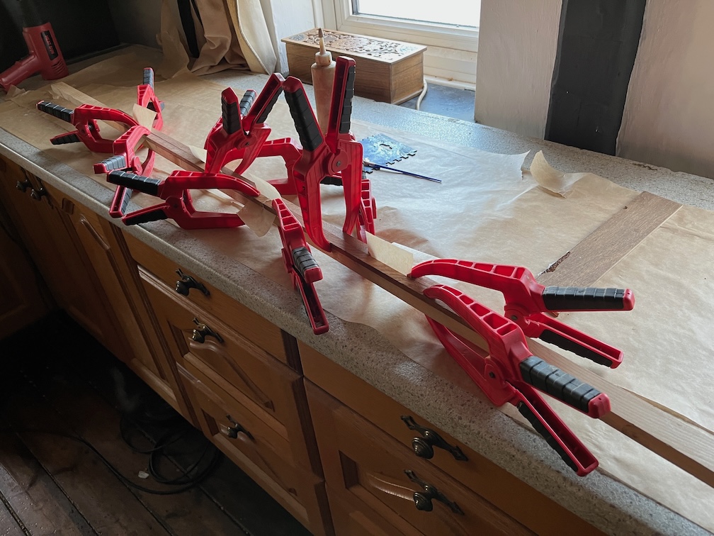
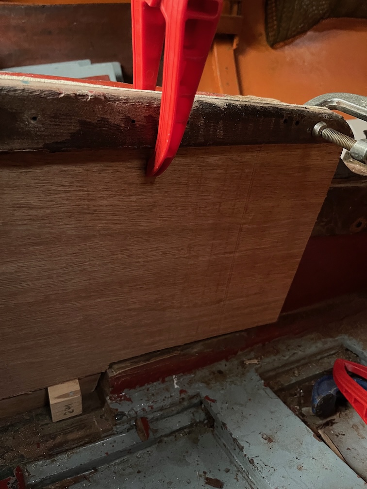
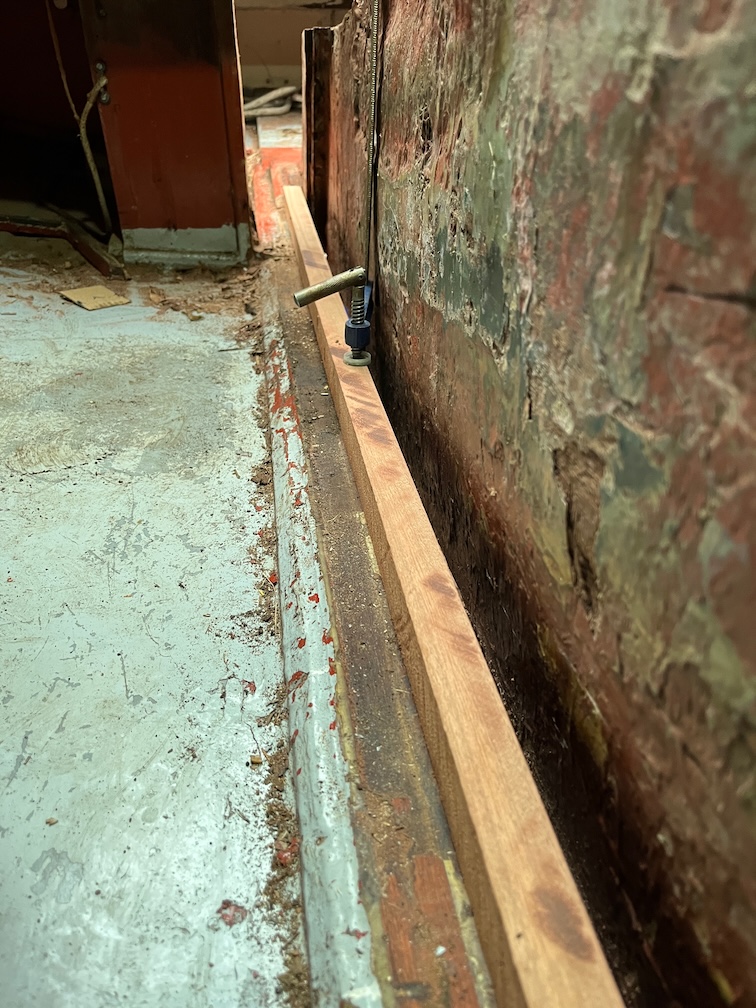
The new runners and the old were coated with neat epoxy and then a layer of thickened epoxy was spread on one side of the new runners. These were put into position with the spacers and clamped. The excess epoxy was scrapped off as much as possible.
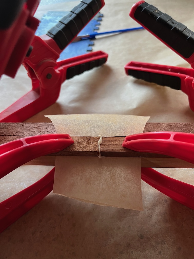
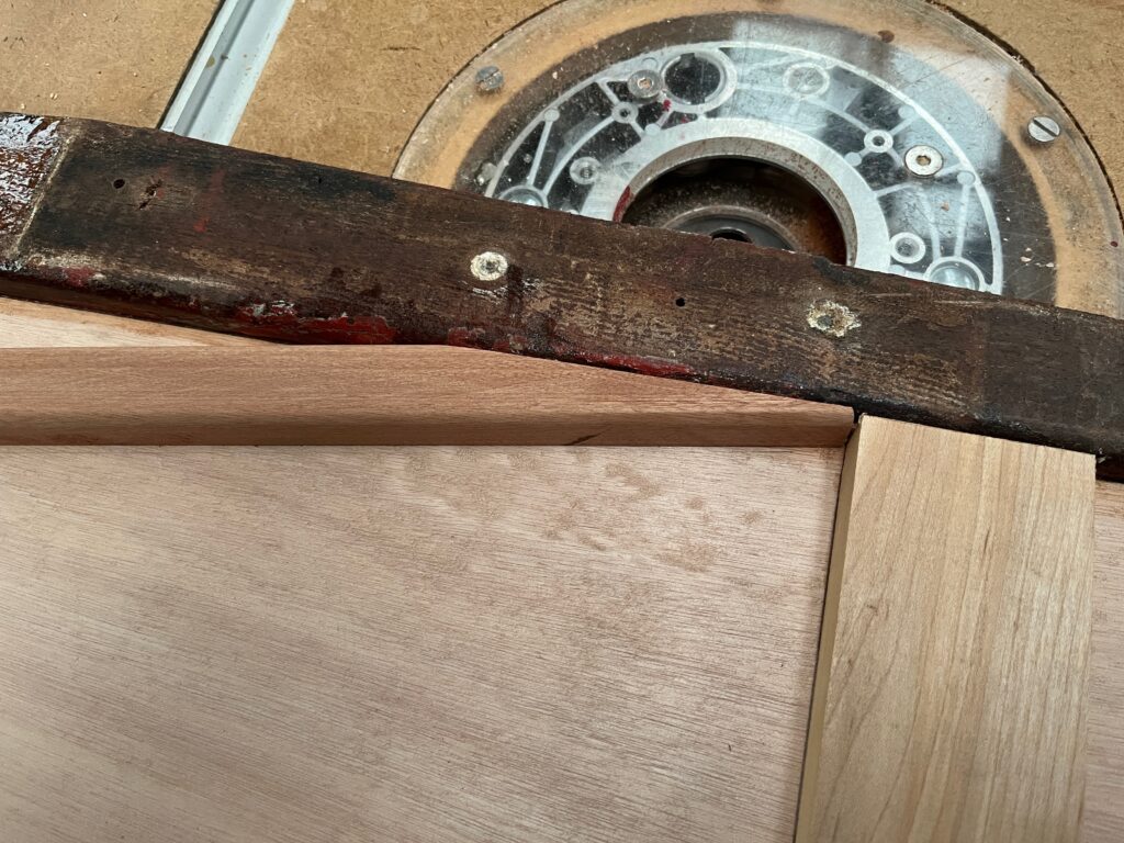
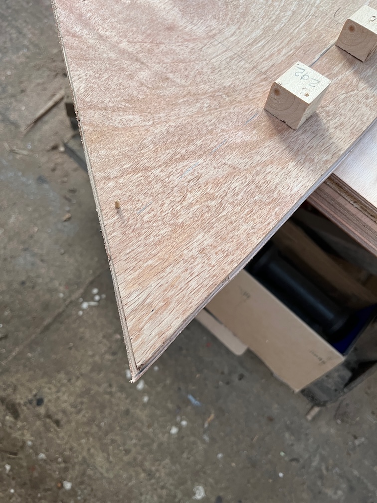
The spacers were removed and a thin mixing stick with a square end was used to scrape any epoxy squeeze out from inside the slot. The new runner piece is bigger than required which will allow me to use a plane to trim back the wood to match the old runners. At least that is the idea.
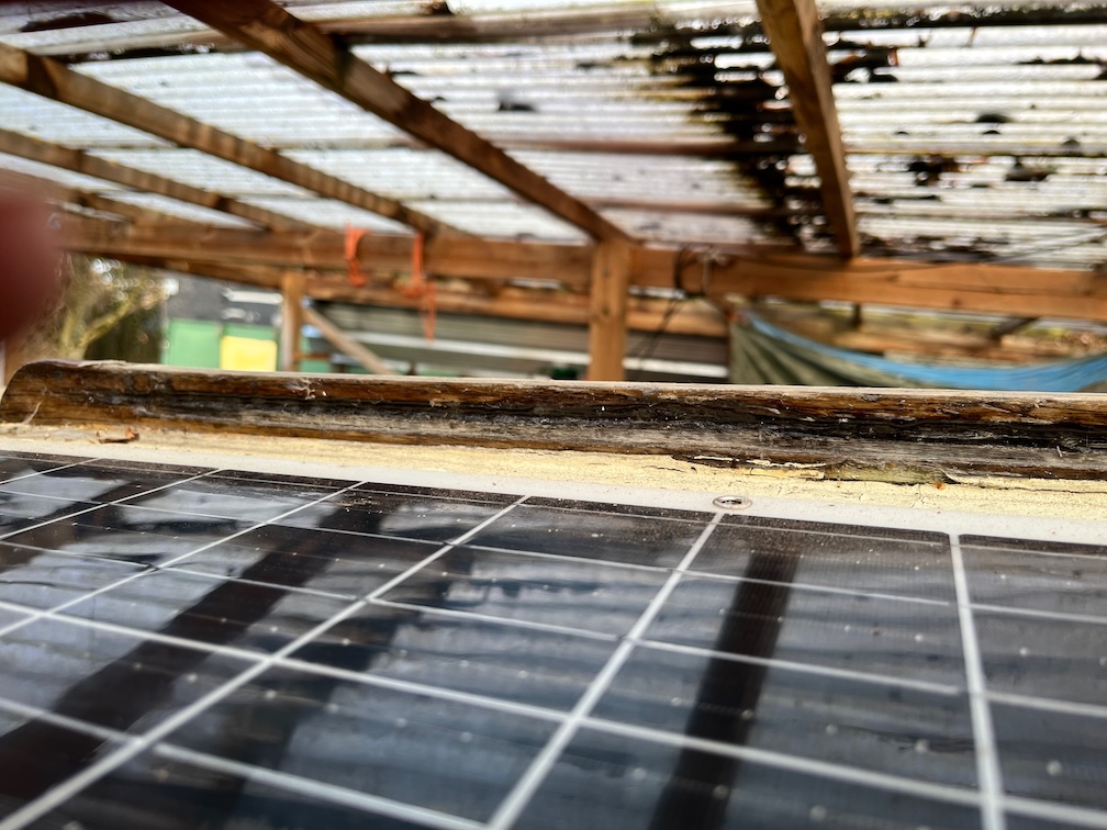
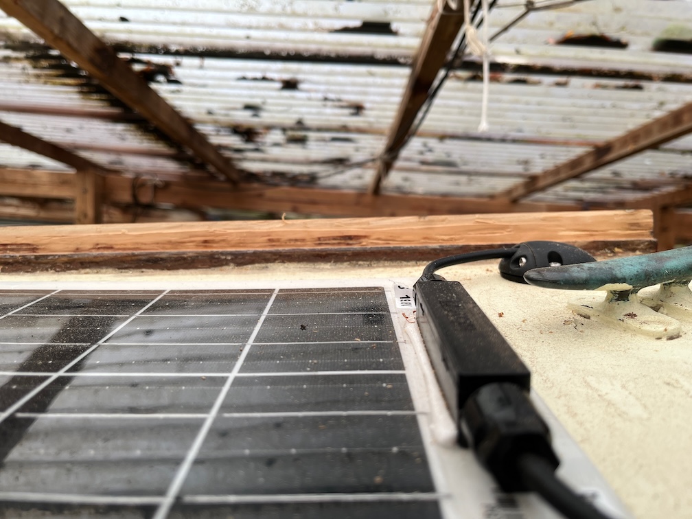
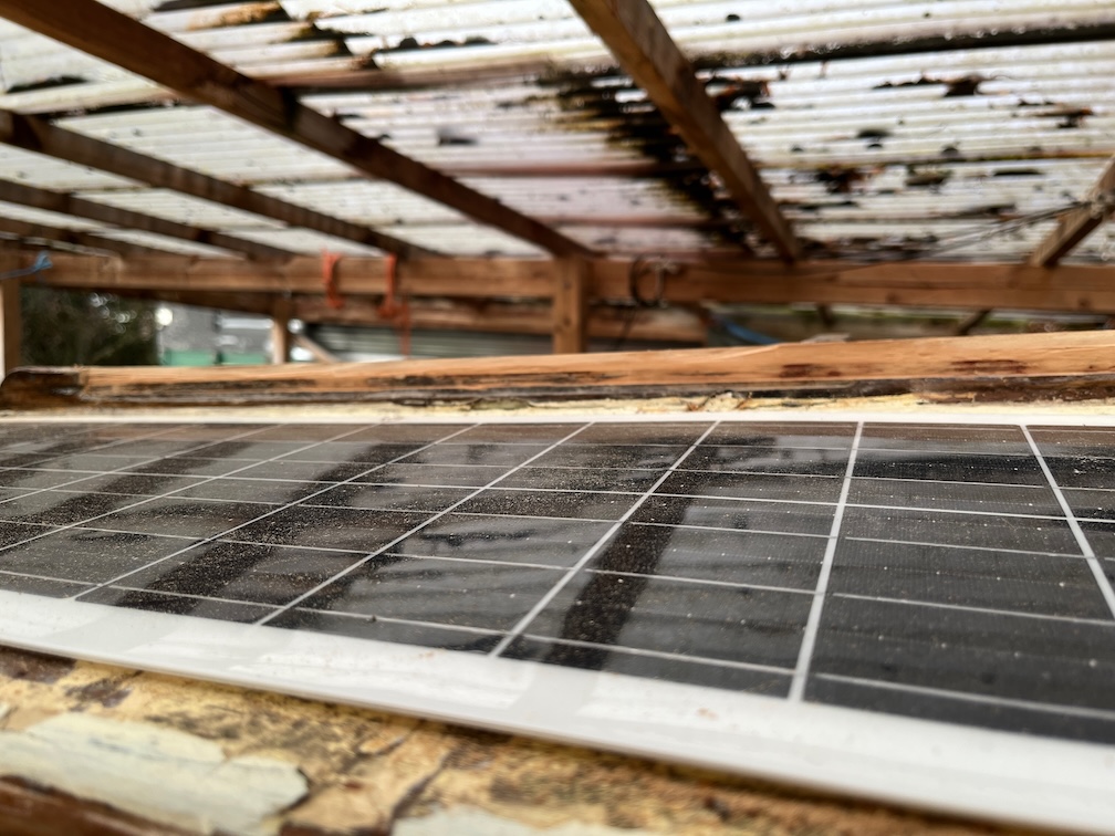
I made enough epoxy to coat several other areas on the coachroof where bare wood was showing.
Peel ply tape covered the layer of epoxy so that I can easily remove the amine blush, a waxy layer that forms on the surface of this epoxy when curing.
Now I shall wait until the epoxy is cured before carrying on.
The forecast for next Monday is 11º C which means that it will be a good day to get some of the exterior glue and epoxy work done. In order to do that I have to prepare the work such that what remains on Monday is just the glue and epoxy work, no preparation.
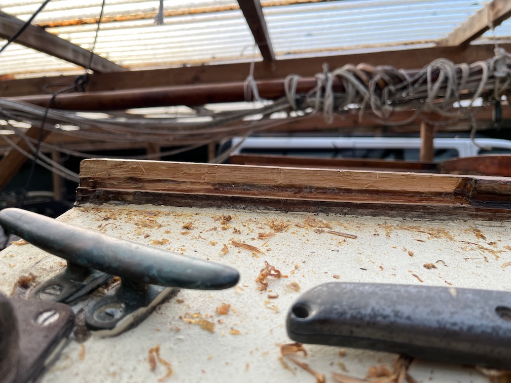
This is the port companionway hatch runner and the grove is not in good shape, having been worn down over the years.
The part that needs to be fixed it the top part of the runner as it is this that prevents the hatch itself from coming off.
The runner needs attention along its entire length and the same is the case for the other side. To fix this the top “overhang” needs to be cut away, the wood and groove cleaned up and a new piece glued in place.
I started on the starboard side, just because, and just worked on a short section to prove the method. I tried using a plane to start with, but this was going to take too long. In the end I clamped a straight edge along the top of the runner where the cut needed to be made and scored the wood deeply with a utility knife. Then I used the multi-tool to cut down from the top following the scored line.
This proved to be quite successful, as you can see, and it did not take long to get the top “overhang” removed.
The groove itself was, in parts, completely blocked with multiple layers of varnish and I had to resort to using a chisel to remove them.
The result is fairly good and I cleaned up the rest using the block plane being careful not to remove any of the bottom of the groove.
The next task is to do the same thing to the port side.
This doesn’t take that long since I have already done the other side and know what to do this time.
I could have spent a lot of time getting both sides really smooth and vertical, but the replacement parts will be fixed using thickened epoxy so there is little point is spending too much time that will end up being wasted effort.
Next the replacements needs to be made and for this I used some left over Sapele from the Naiad rebuild that just happens to be the correct width. The pieces are too short and will need to be glued into longer pieces.
I cut them all to the correct height and took them into the workroom where it is warmer. Useful since my hands were cold again so I could warm them up as well as glueing the new pieces together.
As always with end grain glue ups, I coated the grain with an initial coat of glue and set the pieces aside for 15-20 minutes to let the glue seep into the grain.
After this time, more glue was applied to the pieces and glued together on a former, to keep them straight,
Each joint has a piece of baking paper put between the parts that must not be glued, then the whole thing is put over the Rayburn where it is hot and left for the glue to harden.
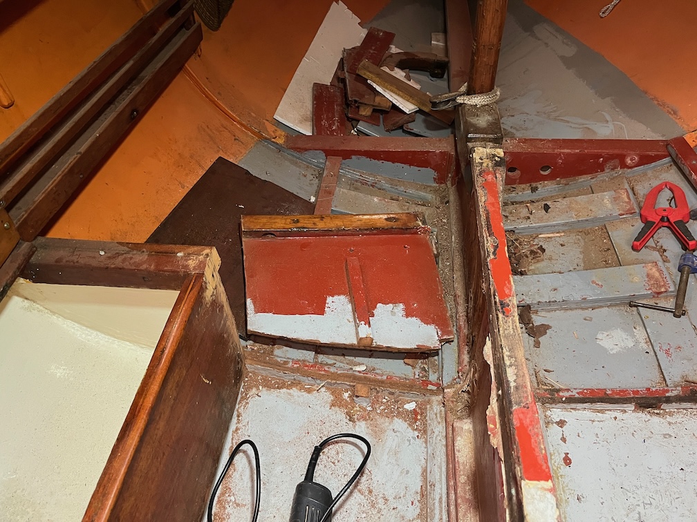
I had some time left over before it got too dark to work, so I attacked the port bulkhead that reinforces the canterplate case.
The work of about ten minutes with the multitool and the bulkhead is cut away. If I am very careful, this piece will be epoxied back into position once the centerplate case has been rebuilt. The starboard side will be rebuilt to match the port side as it was originally, rather than the cut down version.
Just before the light faded I put a second coat of varnish on the clock & barometer board and called it a day.
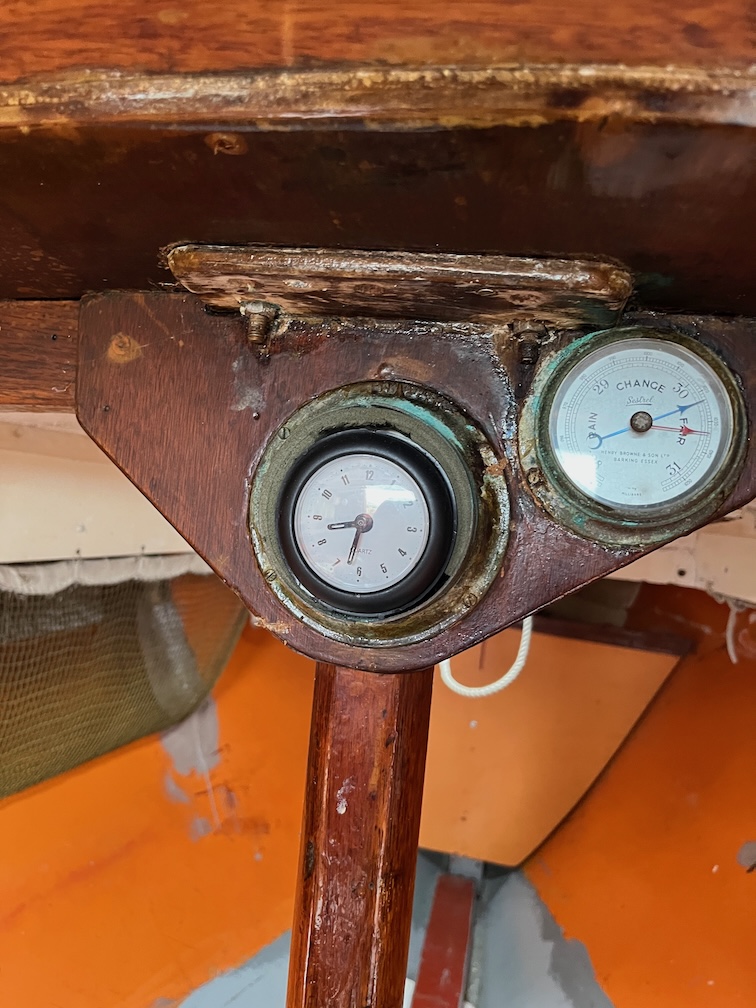
Every time I go into Shoal Waters’ cabin I wince at seeing the clock. It is a brass clock that has lost its clock bit, leaving just the outer case. A modern, plastic clock had been put into the case and the gap between the case and the clock filled with some type of foam strip.
Here it is. It’s quite good fix especially if you don’t want to spend the money on a new one, and they are expensive, but to me, it just looks wrong.
So, I’ve ordered a new brass clock.
Now with a forecast high of zero degrees Celsius today, it’s just 1 Celsius according to my weather station, I didn’t expect to get any work done today, but I decided that I could remove the old brass clock as it’s inside the cabin and therefore would not be so cold. The wind chill is pretty fierce outside today.
So I did.
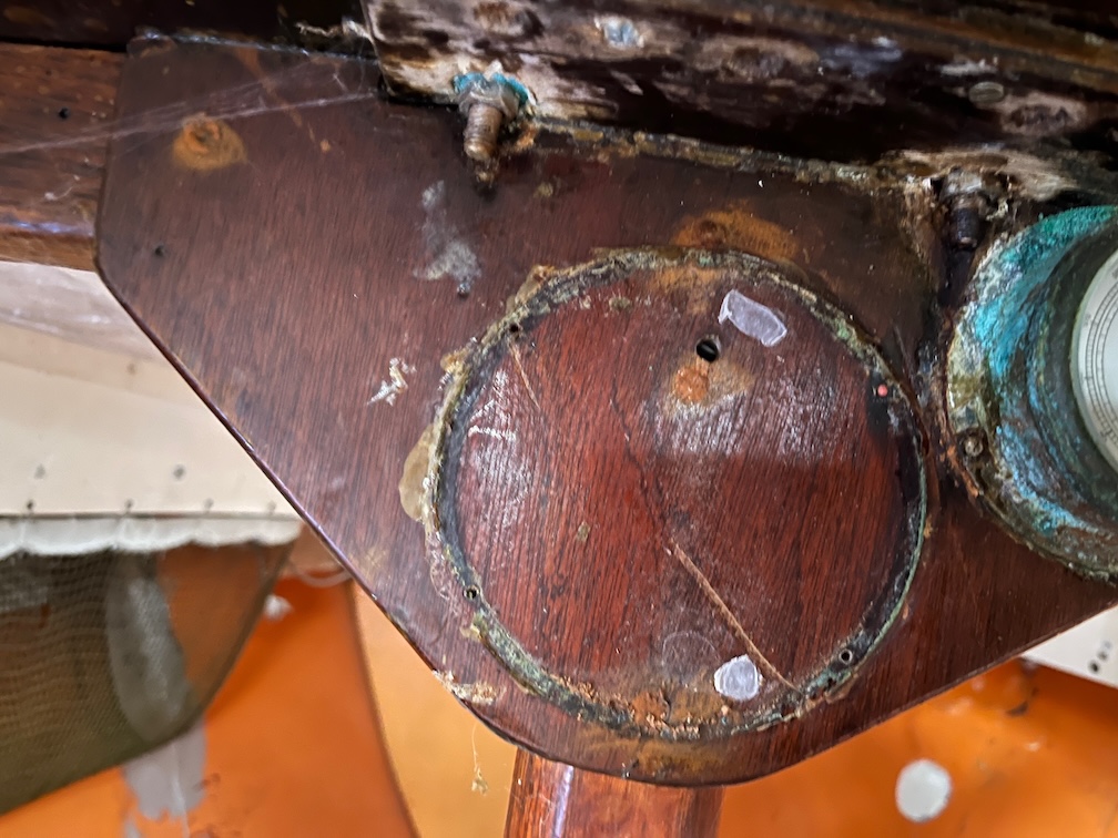
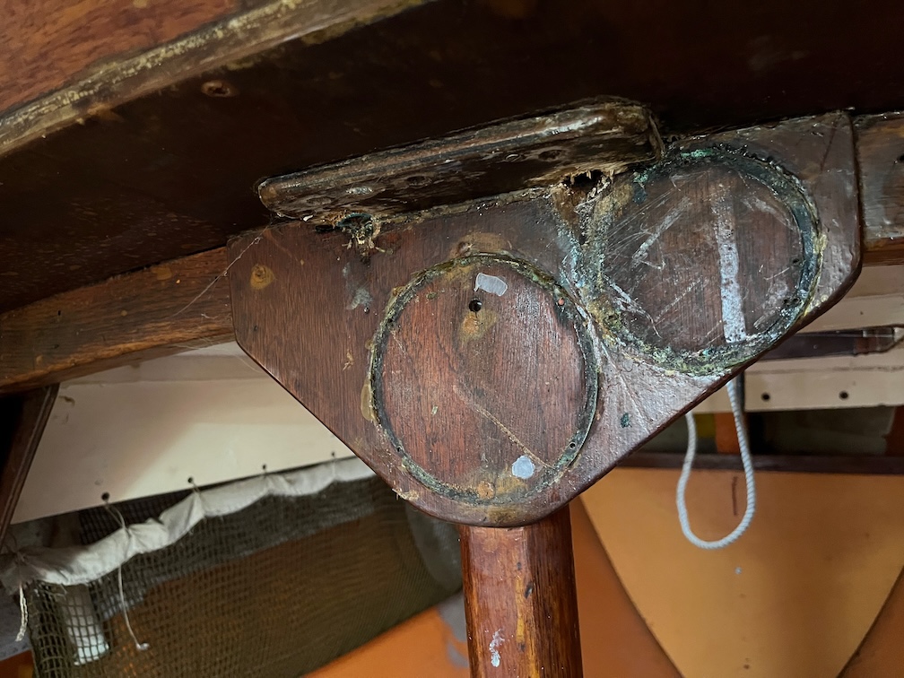
And here is the result. the camera is wonky as I’m trying to hold a light to illuminate the area and hold the camera steady enough to take a non-blurry photo whilst also half kneeling in a small space.
But whilst I was attempting to take this photo I noticed that one of the bolts that holds the tabernacle to the boat is rusted. You can see it right next to the barometer to the right which has a lot of verdigris on the outside which is what rust on brass is called. This is not good. The bolts are stainless and rust on stainless steel is never a good sign. I’ll also have to remove the barometer and clean that up although the verdigris on the small screws holding it to the wood may not come loose. Still, I’ll cross that bridge when I come to it.
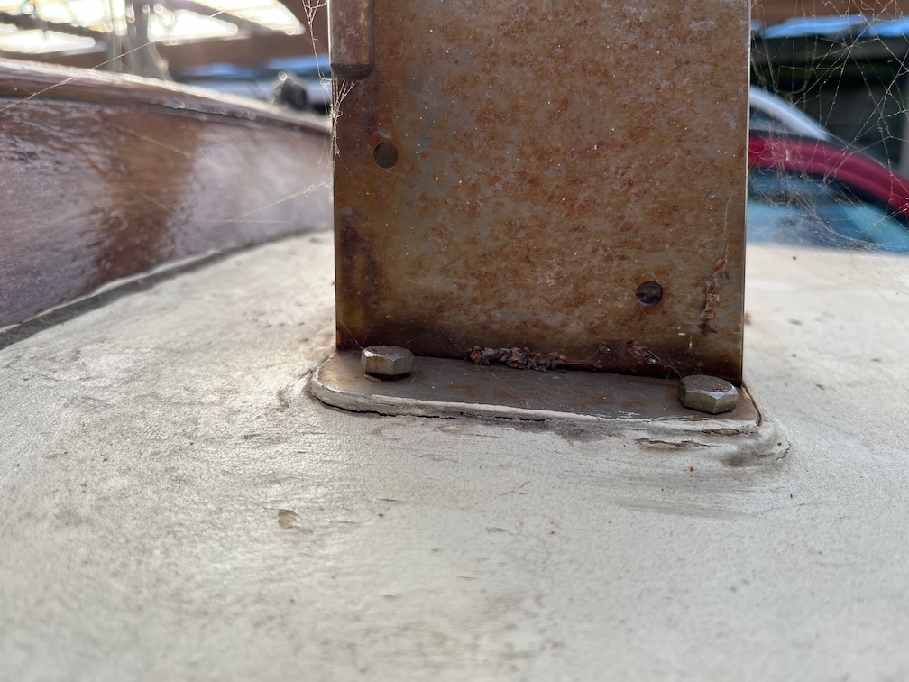
I had a look at the tabernacle from the outside since water was obviously getting in from outside and that meant that the bolt was no longer sealed.
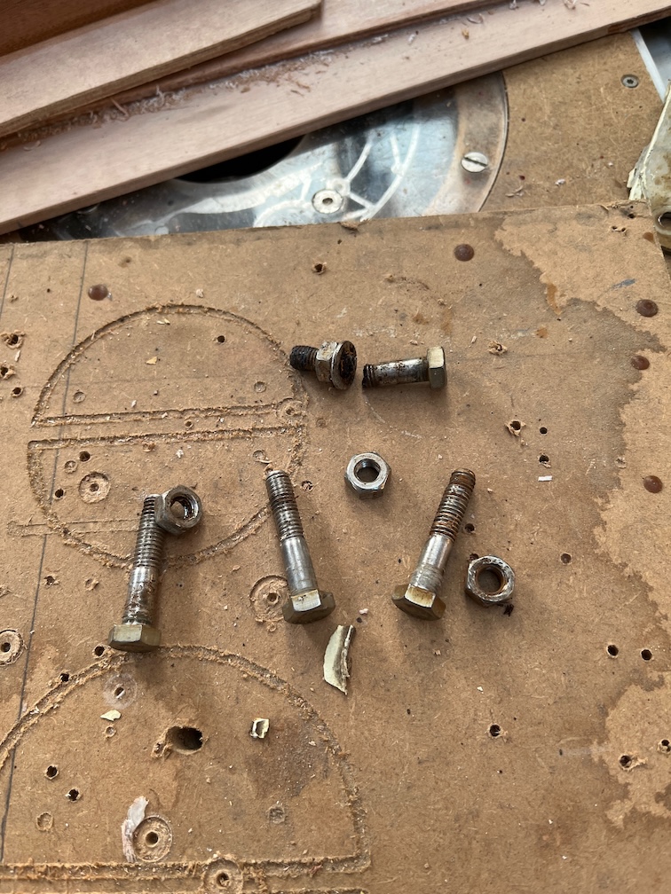
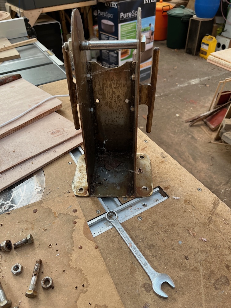
Sure enough, the bolt is no longer tightened down properly, the tabernacle has lifted a little and the sealant has cracked. With rapidly numbing fingers I got out the requisite tools, removed the bolts and the tabernacle and took them into the workshop.
As you can see from above, the severely rusted bolt immediately sheared off the first time I tried to loosen the nut with a spanner. The bolt was rusty just about all the way through. I suspect therefore, that the bolt was originally bolted down tightly but the seal cracked over time and allowed the water in, which in turn caused the bolt to rust and that allowed the tabernacle and thus the bolt to lift making the issue worse. Ferrous Oxide, also known as rust has a volume that is ten times larger than the non-rusted steel and that is how the bolt was allowed to “stretch”.
The tabernacle itself is in good condition with a little surface discolouration. I’ll have to replace the bolts and I’ll make sure that they are marine grade 316, also known as A4, to try and prevent this from happening again. Normally you would only use 304 (or A2) stainless steel above the waterline, and the 316 grade below the waterline, but since these bolts are stainless but still rusting, I’ll pay the extra cost for the 316 grade.
I’ll also need to check the decking under the plywood and the beam underneath for rot and deal with that before I replace the bolts.
At this point I had to pack everything up and go back indoors. My fingers were totally numb and working with tools and numb fingers is never a good idea. I lasted just 30 minutes. The cold tools and the wind chill were too much. The tabernacle bolts had to be removed from the outside and the wind is from the North-West, straight into the Hay Barn.
Now I have to go through the slightly uncomfortable process of warming up very cold fingers.
Time for a cup of tea.
Once my fingers had warmed up I decided to try a few other short jobs. the first was to clear the old sealant from the deck where the tabernacle stands.
This is the state of the deck before I started work…
… and here is the after view. A lot of the deck under the tabernacle seems to be epoxy and I recall Charles writing in “Sailing Just for Fun” p37 footnote:
In May 1997 while Shoal Waters was on a trailer the mast hit an obstruction and ripped the tabernacle out of the foredeck. It was quickly and easily repaired.
I presume that the epoxy I found is part of that repair. I’ll have to clean up more of the remaining sealant and then I’ll probably skim that area with thickened epoxy to smooth it all off and to give it some more rigidity.
You’ll note the piece of Mahogany at the front of the cleaned up area, This is to tip the tabernacle aft a little to compensate for the slope of the foredeck in that area. If this were not done, when the mast was fully upright in the tabernacle, it would lean forward due to the slope.
Having done that and still being able to feel my fingers I moved into the cabin and set about removing the barameter.
The exterior of the barometer has been coated with varnish over the years but this has not prevented the retaining screws from degrading to the point that they could not be unscrewed. I resorted to slipping a flat-bladed screwdriver under the lip and levering the instrument off. It released very easily since the screw threads were now virtually non-existent and thus not gripping the wood any longer. It seemed that the barometer stayed in place due to the varnish than the retaining screws.
With the barometer removed I can now easily sand and revarnish the instrument board. It will also make it easier to replace the one bolt that almost touches the barometer.
I did take the opportunity to give the wood around the bolt holes a good poke with a sharp tool and found that the wood seems to be free from soft spots although there is quite a bit of salt residue that will need to be sanded away before the tabernacle is replaced. I also noted that the piece of wood upon which the clock and barometer were mounted fouls the two aftmost bolt holes and has been partially cut away to allow the bolts to protrude. However, the one on the starboard side hasn’t been removed enough causing the bolt to be canted slightly aft and this will have contributed to the leak,
As part of the work in refitting the bolts, I shall cut the backing board away completely around these holes such that the bolts can sit perpendicular to the deck.
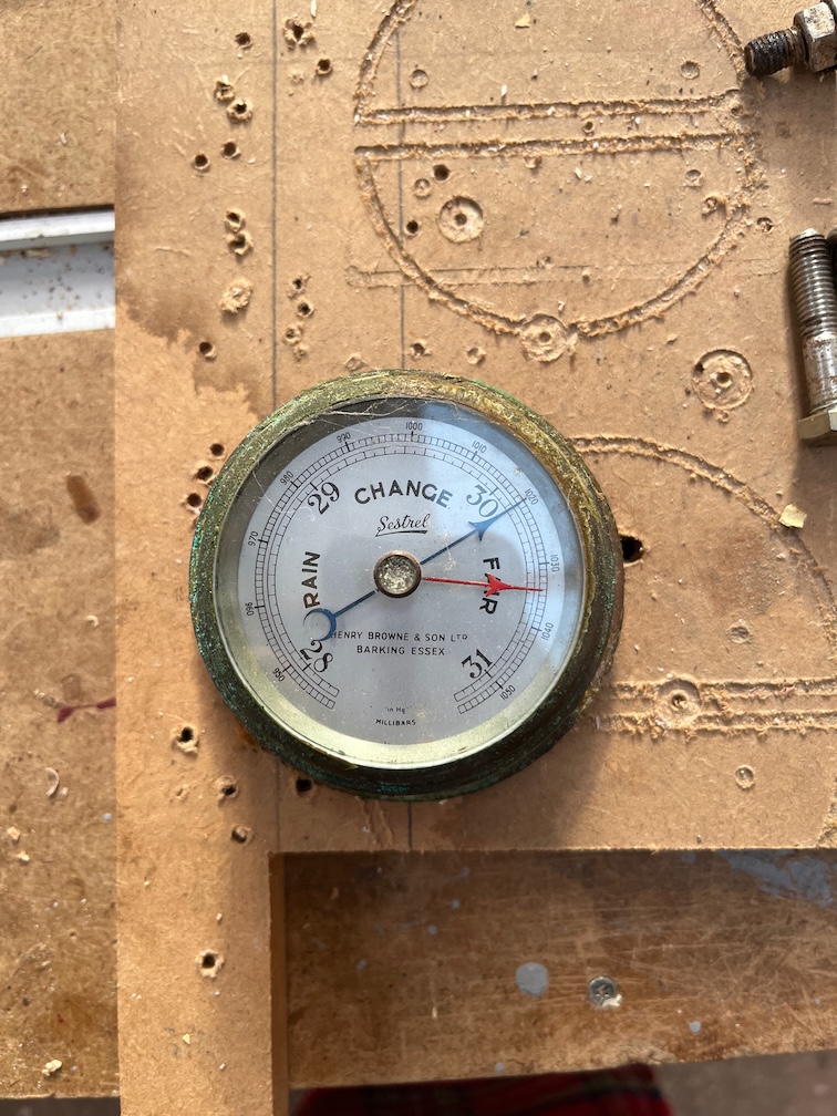
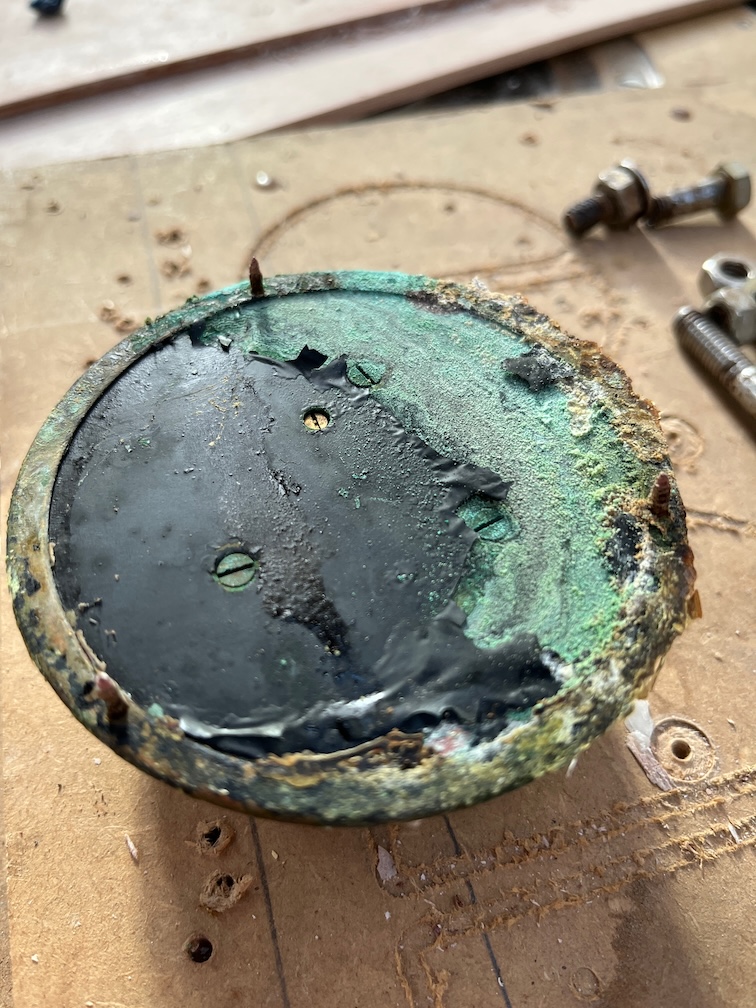
The barometer seems to be in fairly good condition. It is partially covered in old varnish and part of the retaining lips has turned to copper, the zinc having been leached away by the water..
It is quite clear which is the upper side from the level of verdigris on the back and you can clearly see the old varnish and the three screws.
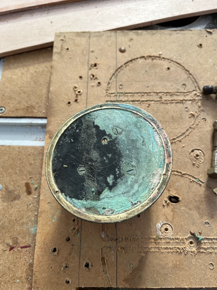
Here it is again but cleaned up a little. You can see the pinkish hue on the rim where the brass has turned to copper.
I don’t know if the barometer still operates, so having cleaned it up a bit more I took it inside to my office where I have the repeater for my weather station. I used the set screw in the back of the instrument to set it to the same value as the pressure reading on the station and I’ll keep an eye on it over the next few days to see if it tracks the same pressure.
If it does then I’ll replace it, if not then it will be retired and a new one purchased and installed in its place. Assuming that I can find one that small in solid brass, that is.
The reason why the centerplate case sides disintegrated is a question that has occupied my mind regularly since I first discovered the issue back at the beginning of August and I have come up with some wild ideas as well as a few prosaic ones. However, bearing in mind Occam’s Razor, I believe that the most likely reason is as follows:
Since the pivot bolt and thus the hole through which it runs, is underwater when the boat is floating, the bolt must be well tightened up in order to prevent the water from seeping through the hole and into the bilges. However, the sides of the case are only 8mm plywood with a stiffening piece on the outside of the case.
You can see the stiffening piece on the side of the new case above.
If the pivot bolt is tightened too much the sides of the case will bend inwards excessively and a spacer is inserted between the sides to prevent this.
The is the spacer. the plate pivots on the centre section and the two wide ends press against the sides of the case. I presume that the spacer was a good fit but not a tight fit and tightening up the pivot bolt did bend the sides of the case in just a little and this made the joint between the case and the spaces very tight, tight enough to stop water from getting into the hole.
So far, so good. Now Charles Stock reinforced the sides of the centerplate case when he was building Shoal Waters and my conjecture is that this added so much stiffness to the sides of the case that when the pivot bolt was tightened enough to stop the water getting into the boat, during the occasional pivot bolt inspection, it prevented the sides of the case from bending inwards slightly and forming a good seal with the spacer. This in turn allowed water to seep into the end grain exposed by the hole in the plywood and over the decades water had been slowly seeping into the original layer of plywood on both sides, eventually causing the disintegration we see today.
This explanation is contingent upon two things only. Firstly that the end grain exposed by hole through the original plywood was not sealed and secondly, the additional stiffness of the case sides prevented a good seal being made between the spacer and the case sides.
All the other explanations I have come up with require more than two contingencies.
Alas, we shall never know if I am right but the mechanism is valid and a concern for the new centerplate sides. To prevent this from happening again is simple, just seal the end grain in the hole.
Simple in concept, but not so simple to achieve reliably, especially when the hole is only 10 mm in diameter and is nearly 40 mm deep. To completely seal the end grain I decided to use a technique that I used for all such holes in Naiad.
I drilled out the hole to 13 mm and placed tape across both ends. The top end was cut to open the hole as seen above.
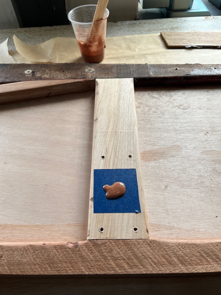
Epoxy thickened with low-density filler was poured into the hole to completely fill it and the epoxy allowed to cure. The epoxy was about the consistency of thick double-cream but liquid enough to easily soak into the sides of the hole, from top to bottom. Once this has completely cured I will sand the epoxy flat with the wood and drill a 10 mm hole through the epoxy which will leave 1.5 mm of epoxy between the hole and the plywood and the hole will be completely sealed.
Overkill?
Certainly, perhaps even overkill to the overkill, but quick and easy to do, so why not?
Time for a cup of tea.
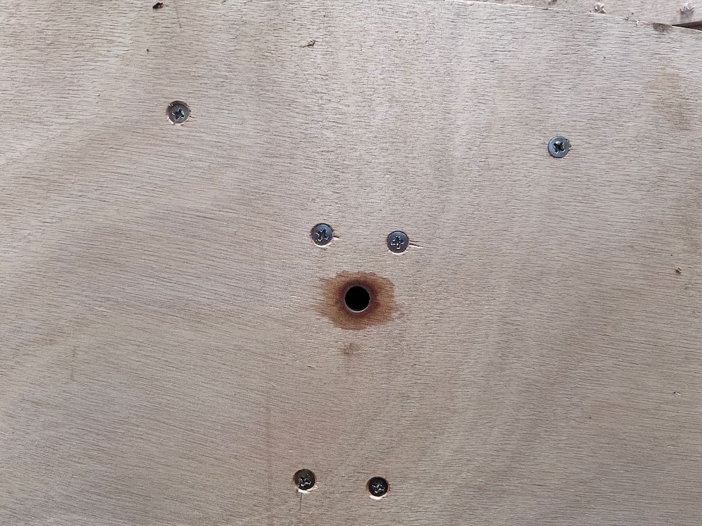
The result after the epoxy has cured and the hole drilled.
Work has continued on the centerplate case sides over the past days, I’ve just not posted anything about it, until today.
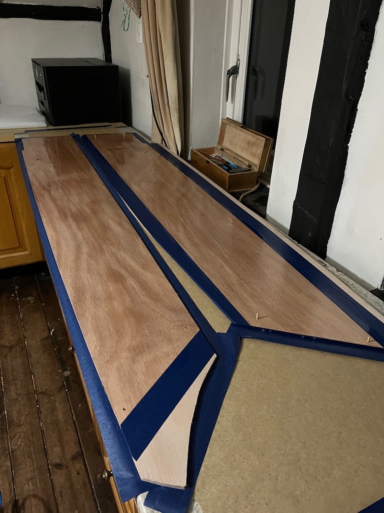
The port side now coated with neat epoxy and much less messy without so much tape.
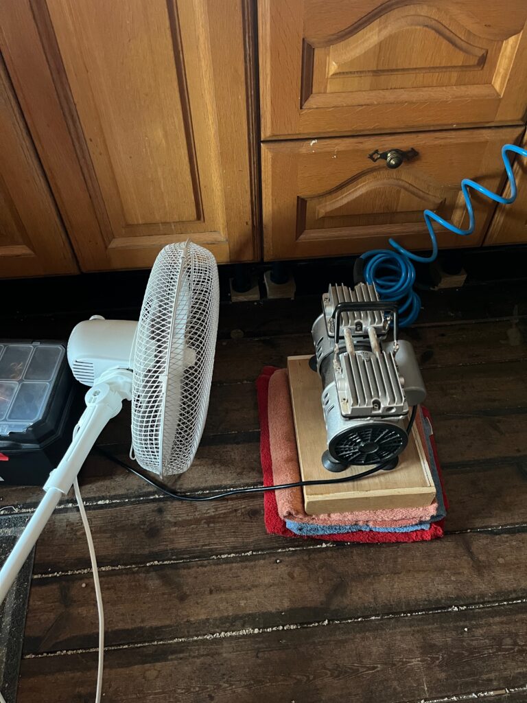
During the vacuuming part of the process, however, the pump started to overheat after an hour and I noticed that it had managed to pull a greater vacuum than before indicating that the seals were better but the pump was working harder as a result. So I resorted to some cooling. After a couple of hours, however, the pump was still too hot, so I ran it for 30 minutes then let it cool for 30 minutes with the fan still going.
Just to prevent the top laminate from lifting during the cooling phase, I put some lead weights on the top. Each of those is 2kg so plenty of downward pressure. Not that I expected the laminate to lift, but there’s not reason not to put the weights on, just to be sure.
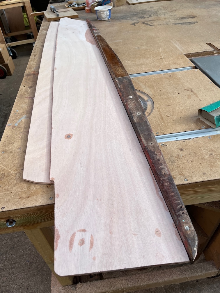
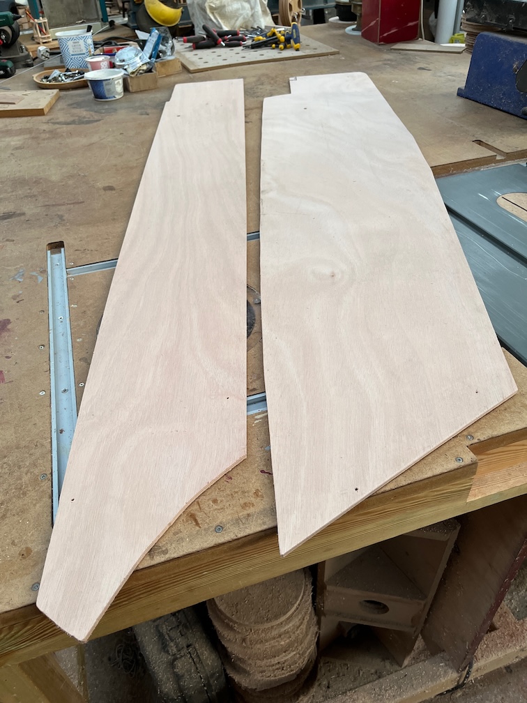
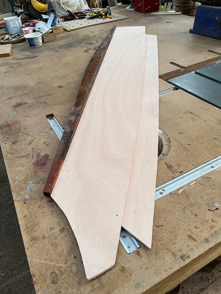
Now I have the two sides laminated up and you can see that one is the mirror of the other. After cleaning up the squeeze out I put the port side aside for the moment since I need to remove the old side from the boat before I can continue with that piece.
But there’s nothing stopping me from working on the starboard side. I clamped the runners in place then dry fitted the side to the space. I had to trim a few sections but once it fit snugly I glued and screwed the top and bottom runners in place and took the workpiece inside to speed up the glue drying.
Once the glue had dried I made the reinforcement at the pivot bolt hole and this was also glued and screwed in place.
Then the diagonal brace was constructed. At least, I presume that it is a brace, I can’t think of any other reason for it except aesthetics. The original case side was just one layer of 8mm plywood so a brace may have been needed. Whatever the reason I decided that I would replace it anyway.
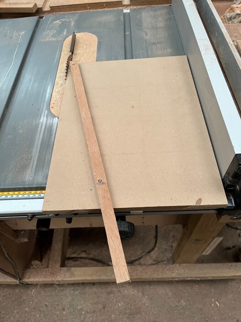
This was a little tricky since the angle of the cut required at the top of the brace is not the same as the one at the bottom. I knocked up a simple scarfing table saw jig for this.
Nothing fancy but it does the job well enough.
The problem at the lower end is that whatever I do, it impinges on one of the screws that holds the bottom runner to the keel. So once the glue has dried I shall drill up through the screw hole and then drill a hole in the brace that is wide enough to allow me to put the screw in and tighten it up. I will plug the hole once the screw is tightened as it will be a water trap otherwise.
Then it was back to the Rayburn to warm the workpiece up. At this point I had to order some more No.8 1″ 316 stainless screws as I’d only bought a pack of 50 previously, and I’ve used 32 on this side alone.
There won’t be any more going in from this side, but there will be some more from the outside and into the end block, but those require screws of a different length, as do the screws into the keel which are longer still. However, I’ll have to do the same for the port side once I start on that.
Once the glue has dried I’ll run a round-over bit in the trim router around some of the edges, just to give a better edge for paint. Right angle edges tend to shed paint quite quickly.
But for today, I think that it is time to pack up. It has been a very successful few days with the few mistakes made being minor.
To be honest, I hadn’t intended to do any work on Shoal Waters today, after all, it is Christmas, but in the end I have been so enthused about the project that I just could not resist. I took the case side down to the workshop for some work.
You see, I made two mistakes with the vacuum bag clamping. Firstly, I used far too much tape and secondly, I really should have stopped the vacuum an hour or two into the process and removed as much of the squeeze out as I could.
I managed to remove most of the tape by hand, and fingernails, but the parts of the tape that had epoxy on just needed something a little sharper.
Here is what I mean about the blue tape. It is right in the corner and under epoxy.
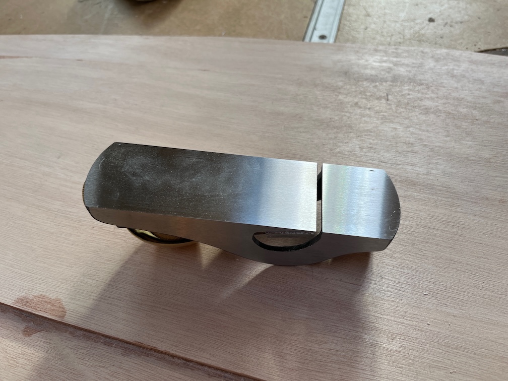
And this is the unremoved squeeze out after the tape has been removed elsewhere. I cleaned as much of this up with a sharp chisel, being very careful as it is a cold day again and then I used one of the special planes I have. So special, in fact, that I keep them in the workroom and not outside so that they do not rust.
One of them is different from standard planes in that the blade extends with across the width of the plae.
Like this.
Using this plane I am able to get all the way into corners provided that they are ninety degrees or more. Anything less than this requires using a chisel for all the excess removal.
The result, as you can see here, is a much better joint and no blue tape. There is still just a little epoxy left in the very corner as I did not want to risk planing away any of the plywood. I will chamfer the edge of the runners a little to allow for this before assembly.
Even without this chamfer the top runner is quite a close fit, almost good enough. But there is a slight gap, so I added the chamfer and when the time for the assembly comes, I’ll make sure that there is plenty of sealant in the joint.
One thing that I did not think about is the pivot bolt hole which you will notice is full of epoxy. This is a good thing as I was planning to do that later in the build anyway. Well, not filling the hole completely, but sealing the edges of the hole with epoxy to prevent any water ingress. All that I need to do now is to drill out the hole and the plywood should be already sealed.
Finally, for the day, I taped up the port side components of the centerplate case that I cut out yesterday.
Much less tape than yesterday and only on those parts of the plywood that need it.
Epoxy day, or one of them at least. Having got up, fed the cats, most important, and done my ablutions, it was time to get started.
Firstly, I needed to tape over the holes in the work pieces, something that I forgot about yesterday. that didn’t take long.
I mixed up eight pumps of resin and hardener and used the mechanical stirrer to mix it up for around two minutes. This new arrangement is much easier than stirring my hand using a mixing stick.
I poured half on one piece and the rest on the other as soon as it was mixed since keeping the epoxy in the mixing cup too long will cause it to kick off and start solidifying, sometimes with enough heat to melt the plastic. Yes, I’ve had that happen in the past. It’s very messy!!
Using a plastic spreader I coated each piece with the epoxy and used a brush to make sure that the plywood was evenly covered.
I put the four registration pins into what will be the bottom piece when clamped and made sure that the holes in the other piece were clear of epoxy. That’s it for now.
It is quite cold again today and we don’t have heating in the workroom as it isn’t used much, so I dragged one of out portable Butane gas heaters in to the room and set that going. That should raise the temperature enough to shorten the cure time.
For now it’s time to make breakfast and..
…have a cup of tea.
This is how it sounds and what it looks like. A little intrusive, but not too much. Mind you, the cats hate it!
After 5 hours of continuous use, the vacuum pump was getting a little too hot for comfort, so I turned it off, removed the plastic and inspected the epoxy. It has kicked off but is not hard. It is, however, sufficiently cured for there to be little chance of the two laminates coming apart, but just to be on the safe side I put some weights on the top. Each of those is 2 kg, which should do the trick.
I’ll leave it like that until the epoxy has hardened properly and then look at taking the tape off and cleaning up the squeeze-out.
The first task of the day is to prepare the work area in the workroom for the epoxy work and, like yesterday, the means clearing things up.
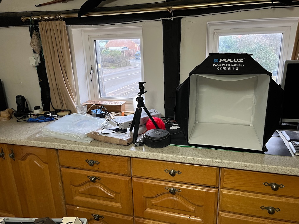
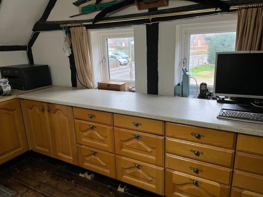
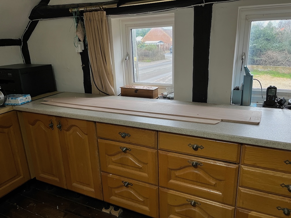
This is the surface I’ll be using for the epoxy work over the next few days and I’ve chosen it for a number of reasons. Firstly, it’s indoors and the temperature is above the minimum of 16 Celsius quoted by the manufacturer. Secondly, it is pretty flat. Not completely. but good enough for this purpose. Thirdly, being a kitchen work surface it is not porous. The only other large, flat surfaces I have are MDF and plywood, neither of which is suitable for vacuum bag clamping unless the entire thing is encased in the plastic sheet.. Fourthly, it is in the work room which, as the name suggests, is set aside for working.
Now, to be on the safe side, I did clear a small area on the worksurface, you can just see it on the left of the photo, and used it to test the vacuum bagging. A piece of the plastic sheet was fixed to the surface using butyl tape, a vacuum gauge and the pump connection added and the pump turned on. This pump is rated to draw down to -0.9 bar and the gauge read -0.85 bar which is more than good enough. I will have to find a way to cut down the noise the pump makes as putting it on the workbench or the floor directly rattles the whole house. I’ll try a folded towel and see if that makes a difference. The pump will be on continuously for about 8 hours, so it needs to be as unobtrusive as possibly.
So, clearing up time it is.
The result is very good. I really ought to keep it in this condition all the time but you know how it is. Any spare space is used for something.
Having thrown away or found a home for just about everything, I washed the surface thoroughly using hot water and washing up liquid, being careful to rinse the surface very well before drying it. I probably used about eight rinsing sessions with clean water each time to make sure that all the detergent was removed.
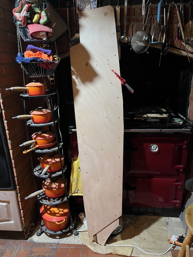
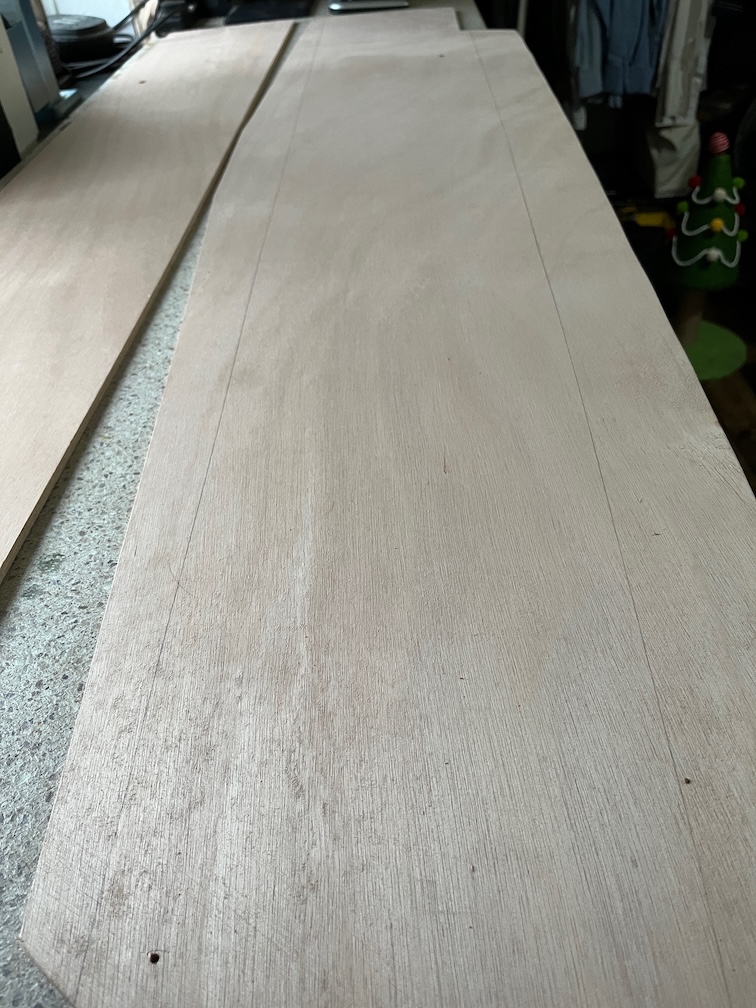
I brought up the plywood that has spent the last 27 hours leaning against the Rayburn and are now dry and laid them out on the surface and pegged them together.
The first epoxy work will be to laminate these two pieces together and that requires two epoxy coats. The first, a coating layer of neat epoxy applied to both mating faces and the second, a coat thickened with a small amount of microfibers, applied to one surface when the coating layer has become tacky. At that point the vacuum bag will be used to clamp the two layers together until the epoxy has cured sufficiently to allow the clamping to be removed.
So, first order of business is to mark the limits of the epoxy.
Nice and easy.
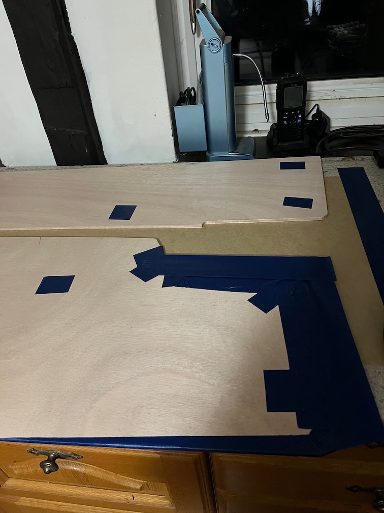
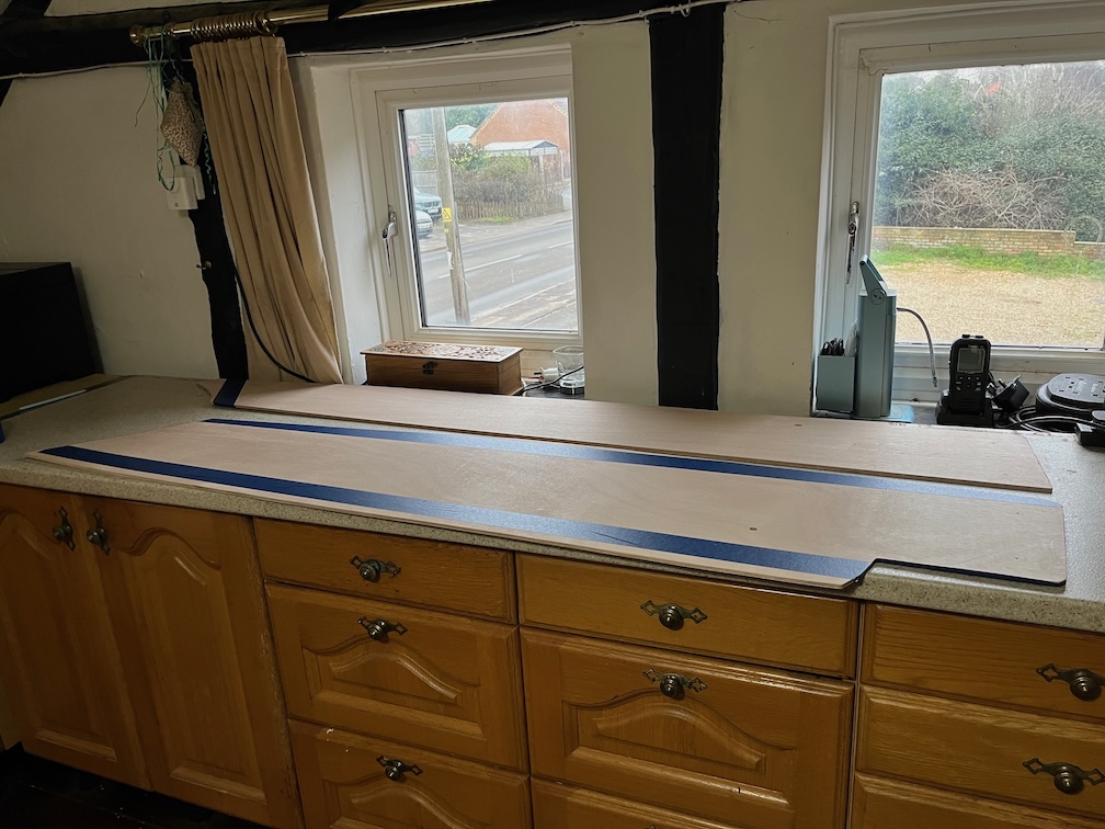
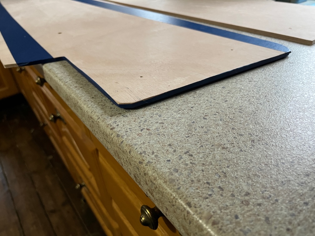
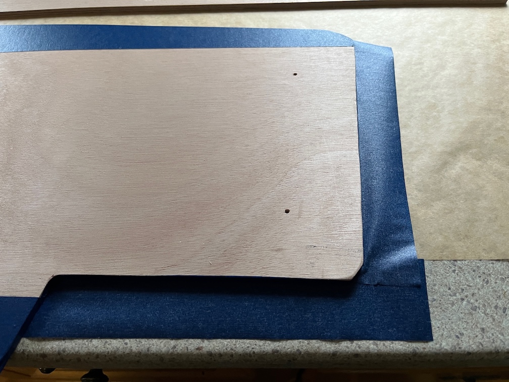
Next blue painter’s tape was put on the plywood on the outside of the lines to stop any excess from coating the plywood where not needed.
I also taped up the edges where I am likely to get epoxy on the edge.
Why do this? Why not just let it coat the edges? After all, all the edges will be epoxy coated eventually.
The answer to this is amine blush, a waxy by product of the curing process that coats the surface of the epoxy and needs ro be removed before painting or varnishing. The normal way to avoid this is to use peel ply, and I will be using this when working on the inner side of the case, but for the edges at this time it is difficult and very messy to use. Leaving this to the end makes it much easier to do.
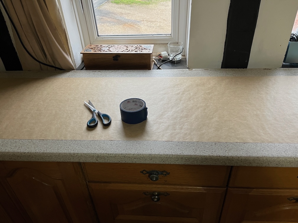
Speaking of mess, I put down some baking paper for the first part of the epoxy work…
…and added some more painter’s tape as a catch tray on the larger of the two pieces.
According to several other makers, one pump each of resin and hardener will cover one square foot of area. Now the area to be covered is 7,425 square cm which is just under 8 square feet, so I’ll need 8 pumps for the coating layers and 4 pumps for the laminating layer.
So far so good.
At this point I’ll have to stop on the epoxy work due to timing issues. The coating will take around thirty minutes, possibly less, but the time to go tacky will be around three hours. Say thirty minutes to set up the vacuum bag and another thirty minutes to mix up and apply the laminating layer. Finally, it will take around eight hours with the pump going before being able to turn it off. In total twelve and a half hours. Now I don’t want the pump to be going after about 6pm, it’s noisy, so I need to start the process at around 05:30.
Guess who’s going to be up very early tomorrow morning !
Time for a cup of tea.
Having had a bit of a break it was time to continue on although, I have to say that it was quite cold outside so I didn’t do much !
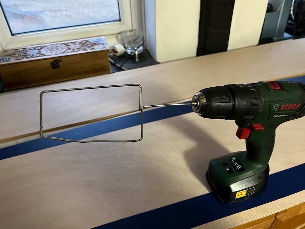
I saw this on https://www.youtube.com/@Nomadboatbuilding, a boat builder on YouTube, which he uses for stirring epoxy. This is usually a tedious process as you have to stir the mixture for around 2 minutes. This allows you to just hold the thing in place for the required time and it does all the work for you. Nomad Boat Builder also uses this in a drill press where he sets it going and goes and does something else for the two minutes and doesn’t even have to hold it.
I have a collection of wire coat hangers in the workshop just for things like this and after a few minutes I had an epoxy stirring thing. You just have to remember to use the slow setting on the drill !!
I also marked and drilled the locating holes for the other side pieces and I’ll cut those out once the epoxy work has been done indoors.
Today is the day I start to cut out and construct the starboard side of the centerplate case. So, bright and early I hied me down to the workshop to make a start, only to realise that before I can cut a single piece of marine plywood, I have to clear up.
A lot !
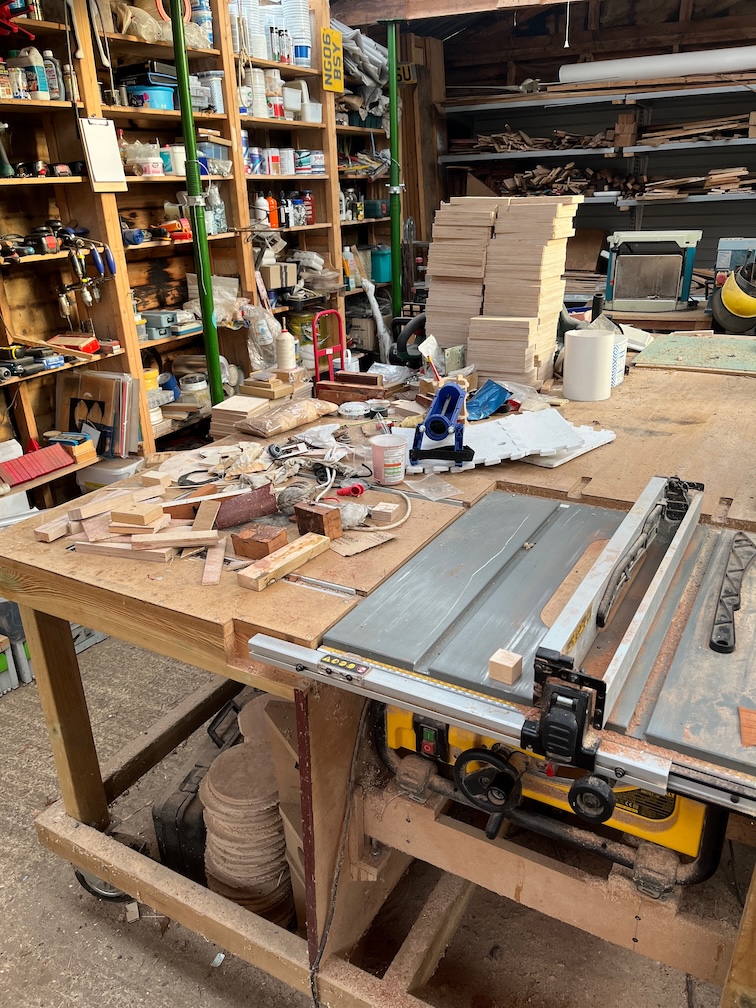
This is the state of the work table and what you can’t see under that lot is the router and I’ll need that soon. That looks like chaos but it isn’t as random as it may seem.
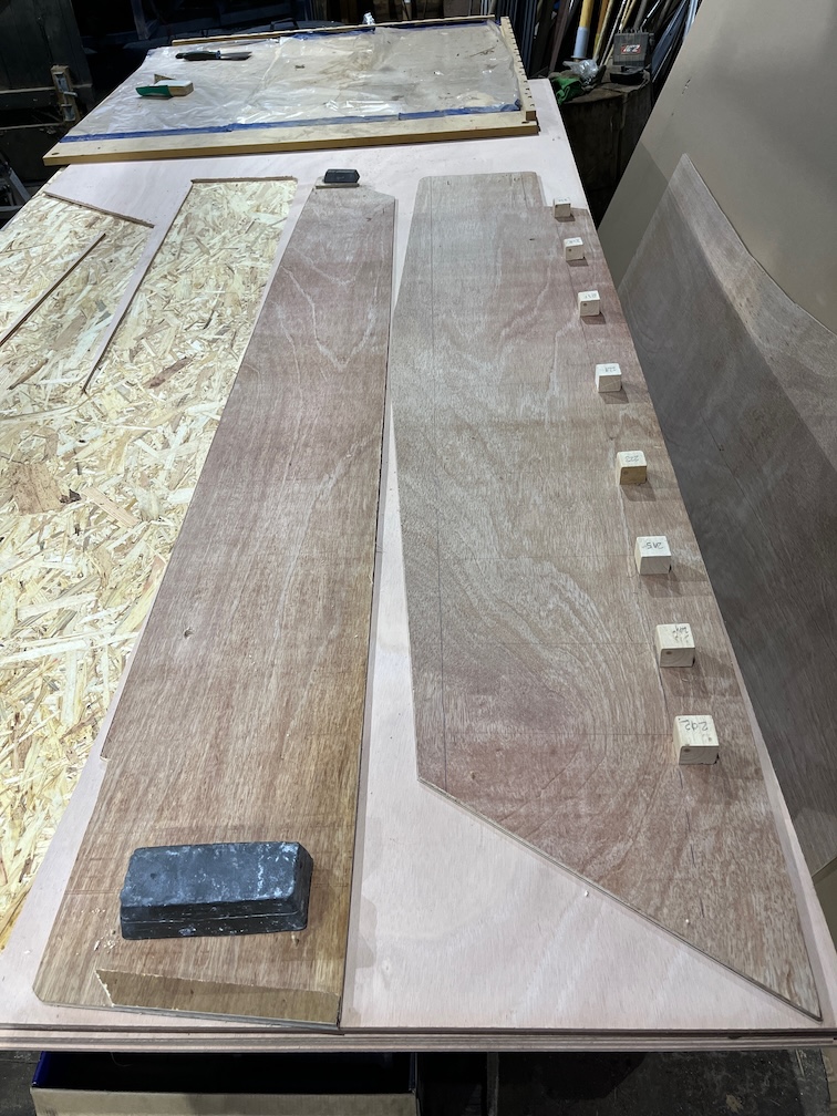
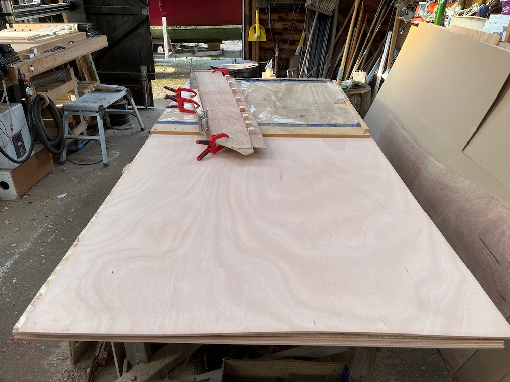
This is the plywood cutting table and you can see the mess that has on it at the top of the photo. Again, if looks chaotic but there is some organisation in the mess. Still, it all has to be removed from the table for two reasons. Firstly, the marine plywood is under the shuttering ply that you can see on the top and secondly, I need at least 6′ of cleared space to cut the pieces and the entire table is just 8′ long.
So I spent the rest of the morning doing a massive cleanup of those two tables. The junk, rubbish and such like got binned, some wooden scraps were put on the fire. That was a mistake since they were damp and the workshop filled with smoke. I had to open all three doors to allow the very light breeze to blow that away.
Then the remainder was sorted into boat bits, non-boat bit and tools. Then, starting with the tools, a home as found for all of them except the thirty or so T-bar hex keys I have. those were put out of the way for now, I’ll have to make some sort of rack for those. Mind you, I’ve been saying that for the last two years.
The non-boat bits were found a home and the boat bits were divided into Shoal Waters’ bits, Naiad’s bits and other and then sorted out. I also went through the pile of wood removed from Shoal Waters and put the usable chunks somewhere as I will be wanting to use those for making other parts for the boat later on.
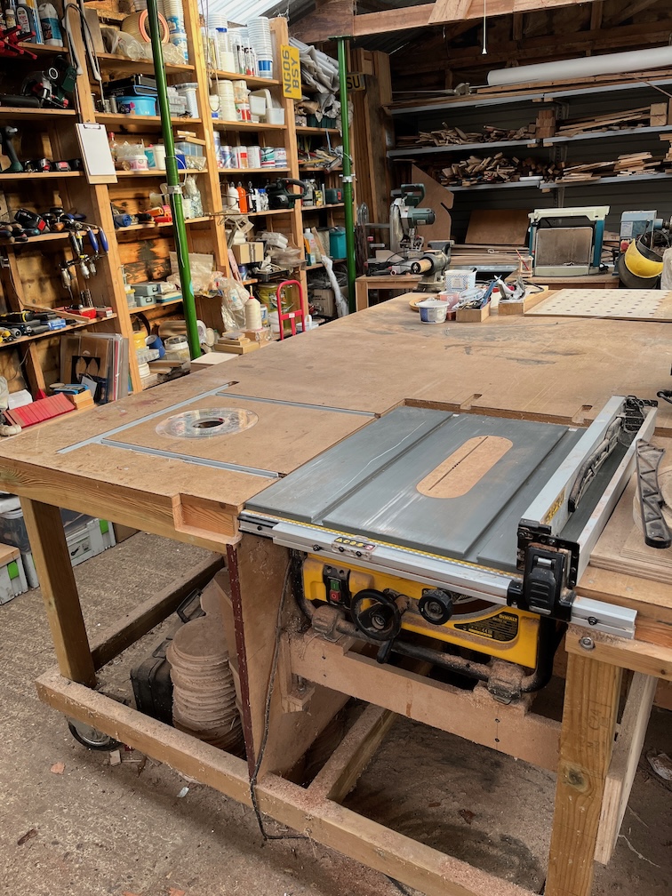
And here is the result. A fairly clean and uncluttered table, you can even see the router.
And the plywood cutting table, also clean and uncluttered with a piece of 6 mm marine plywood on top, ready to go.
However, by this point my throat was dry and dusty from sweeping up the dust and sawdust, so…
Time for a cup of tea.
Some time later…
Having taken a break and had some lunch, it was time to start cutting the inner and outer sides for the centerplate case.
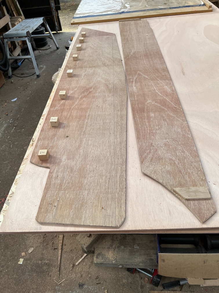
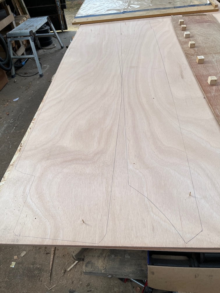
I arranged the two templates on the marine ply making sure that they didn’t take up more than half the width of the sheet. I drilled the locating holes in the marine ply so that I can locate the two pieces later on. Then I drew around each template.
This is the result. I used a utility knife to score along the pencil lines where the lines cross the grain to prevent tear out.
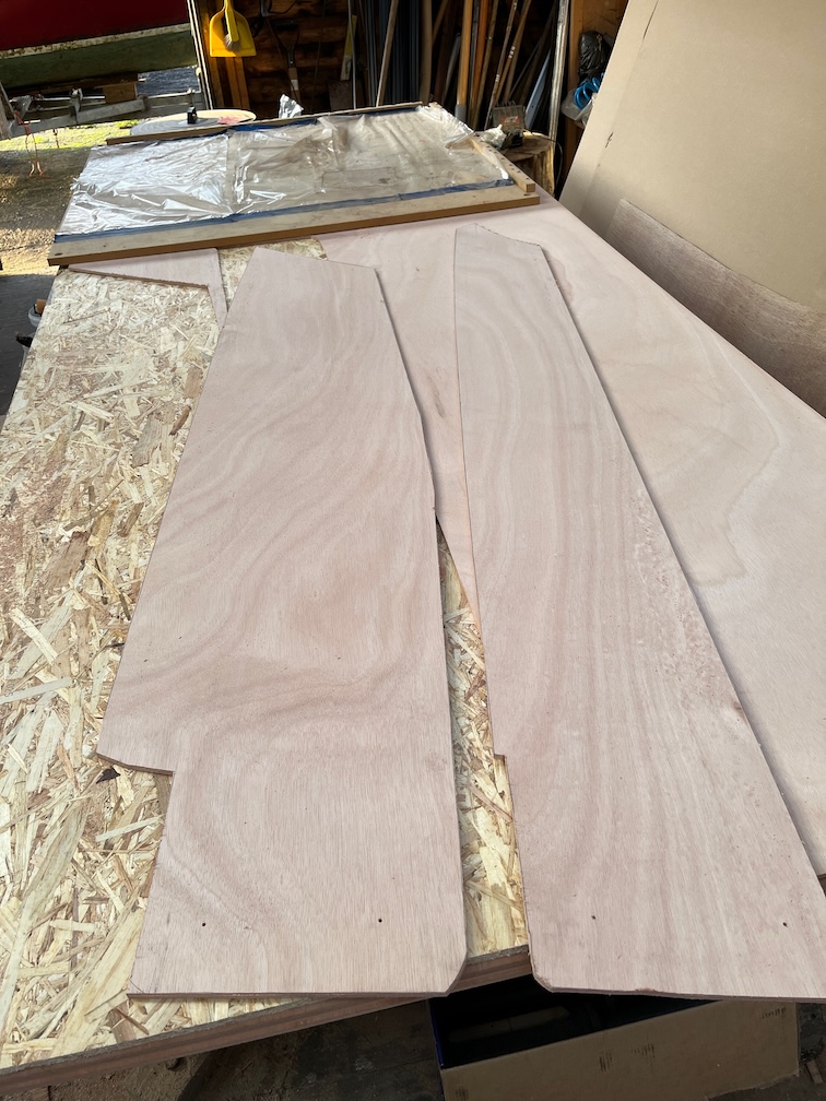
The pieces were cut out using a jigsaw and I tried to keep just on the outside of the pencil lines. The two pieces came out quite well. I used 120 grit sandpaper to tidy up the edges.
Once that was done I put the templates onto the marine ply using the locating holes to get them in the correct position.
You can see the the marine plywood protrudes a little past the template. I used a splodge of hot glue at either end to ensure that the pieces stayed together and then it was over to the router.
I used a top following trim router bit to cut the marine ply to the exact size of the templates. An easy job now that the work table is cleared.
Another view of the template on top of the marine ply after being trimmed.
I didn’t use much hot glue deliberately so the pieces came apart easily without destroying the expensive marine ply nor the cheap template.
It Is quite satisfying to peel the hot glue off the wood in one piece.
So, there we are. The inner and outer case laminates for the starboard side of the centerplate case ready to be epoxied together.
I put the two pieces together using the locating holes to get them in the correct position and put the top runner in place, just to see what it looked like.
What is quite amazing is that the time from laying the templates on the marine plywood to taking this photo of the two completed laminates is just one hour, and the result is pretty much perfect. I don’t need to offer these up to the boat to know that they will fit. I will, but I don’t need to. The templates fitted and so will these.
The other nice thing about making templates is that you know that the templates are temporary and made of cheap plywood, so if you make a mistake, no big deal. You patch it and carry on. And when it comes time to make the other side, well the templates are ready to be used for that as well.
The next step in the process is to epoxy these two pieces together and for that I’ll be working in the house where the temperature is more suited to epoxy work.
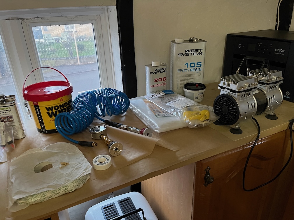
Here are most of the pieces for the vacuum bagging. Vacuum pump, epoxy and pumps, hose and fittings, vacuum gauge, butyl tape, teflon tape, heavy duty plastic sheet and Wonder Wipes. I still have to find suitable netting for the breather layer and a sturdy flat piece of wood that is flat, long enough and wide enough on which to place the laminates, but for today, I’m done.
Even though the temperature is several degrees warmer than yesterday, I didn’t make an early start because, well, it’s Sunday.
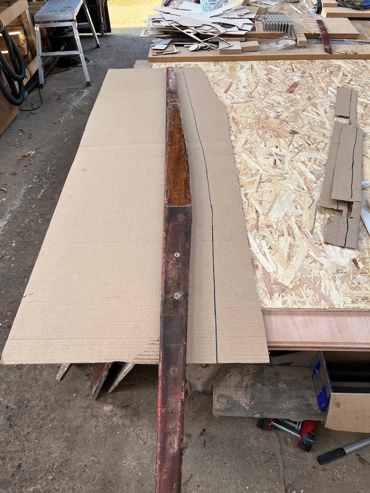
The first task of the day is to complete the outer plywood template and to that end I took the top runner and the template, that had been curing and drying indoors, down to the workshop.
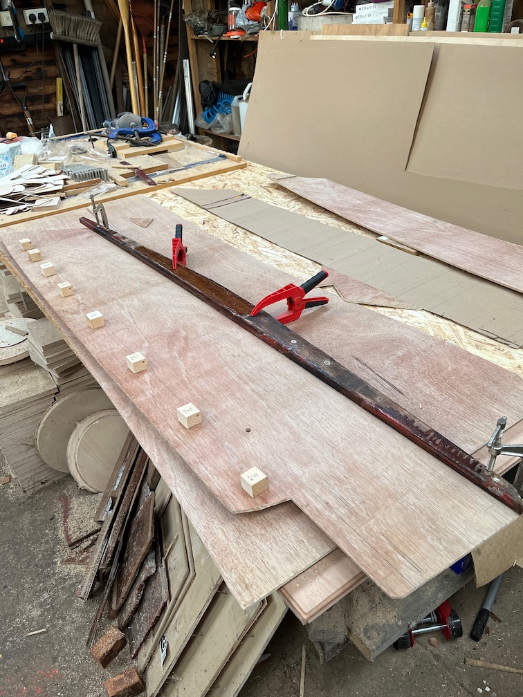
The top runner was clamped to the inner template in the correct position such that the outer template can be adjusted to fit between the runner and the block.
This is the result after several adjustments using the belt sander being careful only to take off small increments at a time. I discovered that contrary to my previous thought that the bottom of the top runner is not straight but curves down slightly at either end. By slightly I mean about 1 mm at the front and 3 mm at the back. Still, this is 6 mm cheap plywood and it doesn’t take much work with the belt sander to remove the excess.
The aft end of the outer template will probably need to be adjusted since I gauged the correct line by eye at this point as the bottom runner hasn’t been made yet.
As you can see here, the outer template looks as though it meets the correct line but I won’t know for sure until the bottom runner is in place.
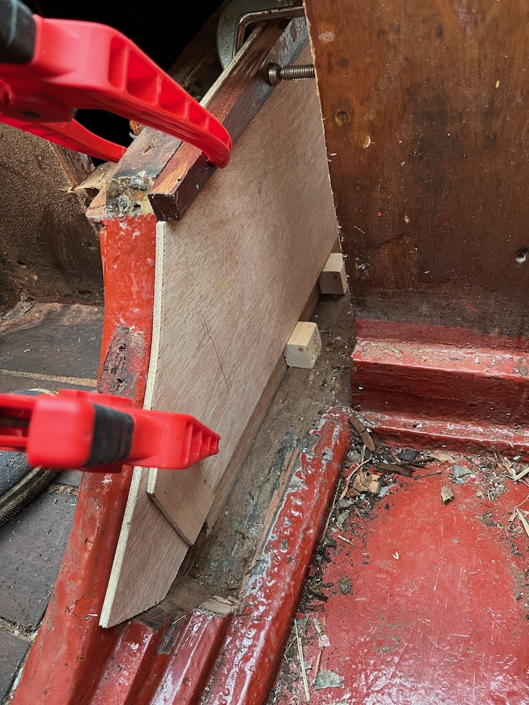
With the two templates clamped together it was an easy job to slide the case side into place and I was able to see how it looks. It was a trifle awkward with all the cramps hanging off the side, but once inside the cabin the side fitted well into the space.
The very front end will need a little more work at the bottom, but I think I’ll not worry about that for the template and cut the real pieces oversize at that end and then adjust the real plywood to make a tight fit.
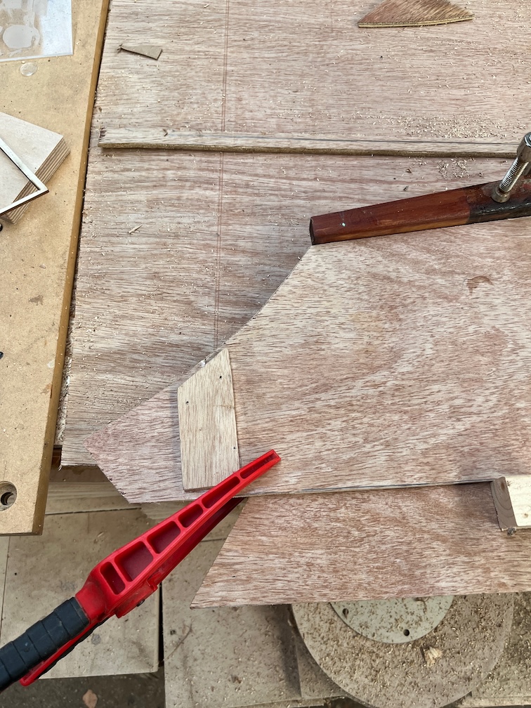
I did add a small extension to the front end of the outer template and I’ll cut that back to match the inner template once the glue has fully cured. Cyanoacrylate glue (or CA glue also known as SuperGlue) this time, so it didn’t take long.
This is the result of a little more work with the belt sander and this completes the outer template.
Time to move onto the next part, but first…
Time for a cup of tea.
The next task on the list is to make the bottom runner. This is 25 mm wide, 30 mm high and about 1.6m long. It will be screwed and glued to the outside of the case and screwed down against the keel. When it is fitted it will have adhesive on the bottom so as to make a good waterproof seal with the keel.
I bought a plank of Sapele that is 2500mm long, 150 mm wide and 38 mm thick and the bottom runners for both sides will be cut from this.
The cutting of the runners was straightforward, but both ends needed to be cut at an angle to match the runners already in place.
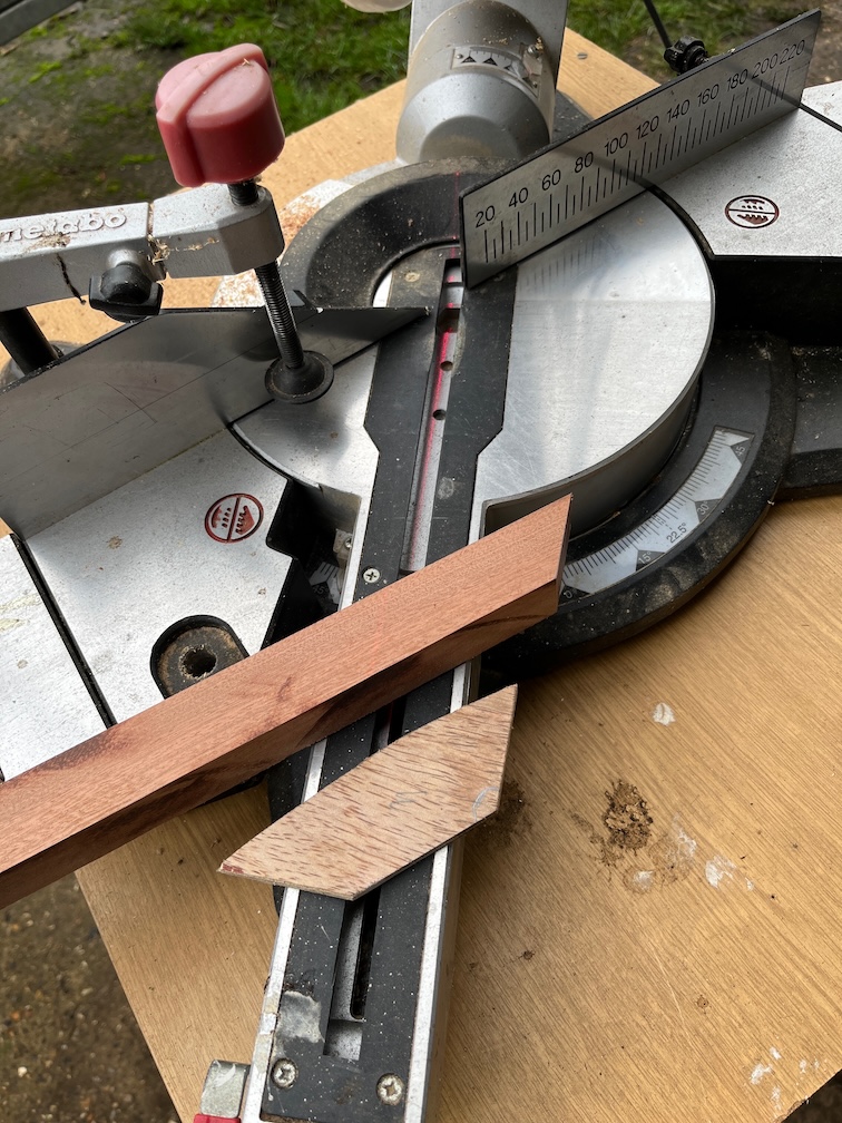
I cut a plywood template first and the used the mitre saw to cut the runner. all easy stuff. This is the aft end and the first end cut.
The forward end was a little more complicated to cut since the keel has a curve in and I had to kneel on the runner to press it to the keel in order to get the correct angle. Once again it was a case of little by little until the fit was as good as I was going to get.
I clamped the runner to the keel with an F-cramp to check the fit.
And all seemed to be well. You can see that there is a slight gap between the runner and the keel here but it was a little too difficult to get another cramp in here, so I didn’t bother.
So, after some time of destruction and template making, the construction of the centerplate case replacement sides has begun. I had a very late lunch at this point and decided that this was a good plate to stop the case work for today. The next part is cutting out the side pieces from the marine plywood and I want to be awake and rested for that.
But if I can find a couple of small jobs to do then I might do those this afternoon, but don’t bank on it !