After the usual round of applying varnish to various parts of the boat, I took a look at the case side.
Here I have removed the peel ply and the result is pretty good. It will need sanding but that was expected. For now, I shall put it by the Rayburn to keep warm to allow the epoxy to reach full strength before I take sand paper to it.
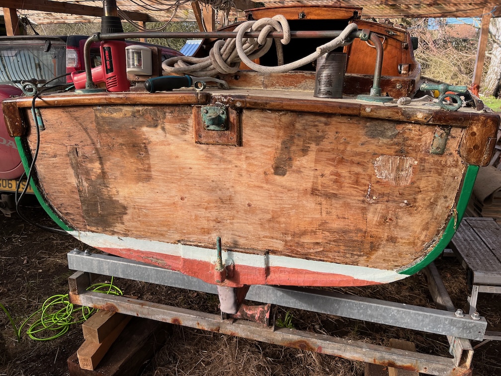
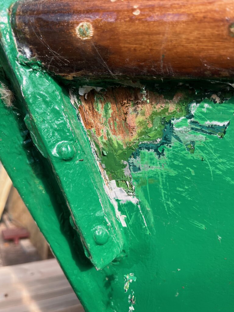
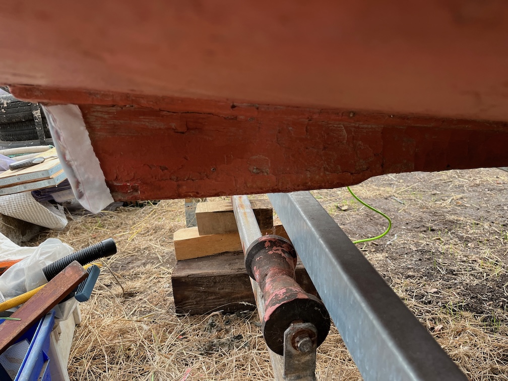
After that I turned my attention to the transom. Armed with hot air gun and a scraper it was the work of only half an hour to remove the paint and varnish. I say paint, but I think it is a coloured varnish rather than a paint and you can see why it was put on. There are several damaged areas as well as dark areas where the wood has suffered water damage.
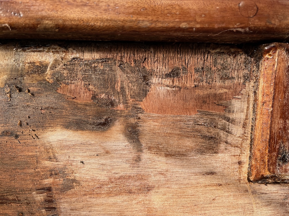
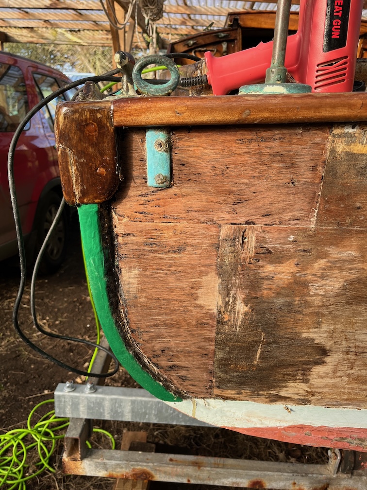
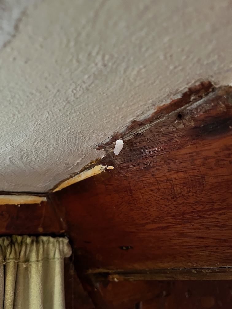
This is an area that needs some attention, at the top of the transom just to the left of the rudder gudgeon. Here is looks as though the plywood has been sanded too aggressively and that has removed the outer layer of the plywood. The exposed and rough grain will wick water easily and although no damaged seems to have occurred as yet, this area needs to be sealed to prevent water ingress.
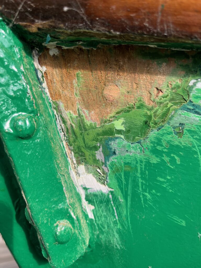
This was the most surprising area. It looks to be a massive repair and I suspect that it was carried out due to severe water damage.
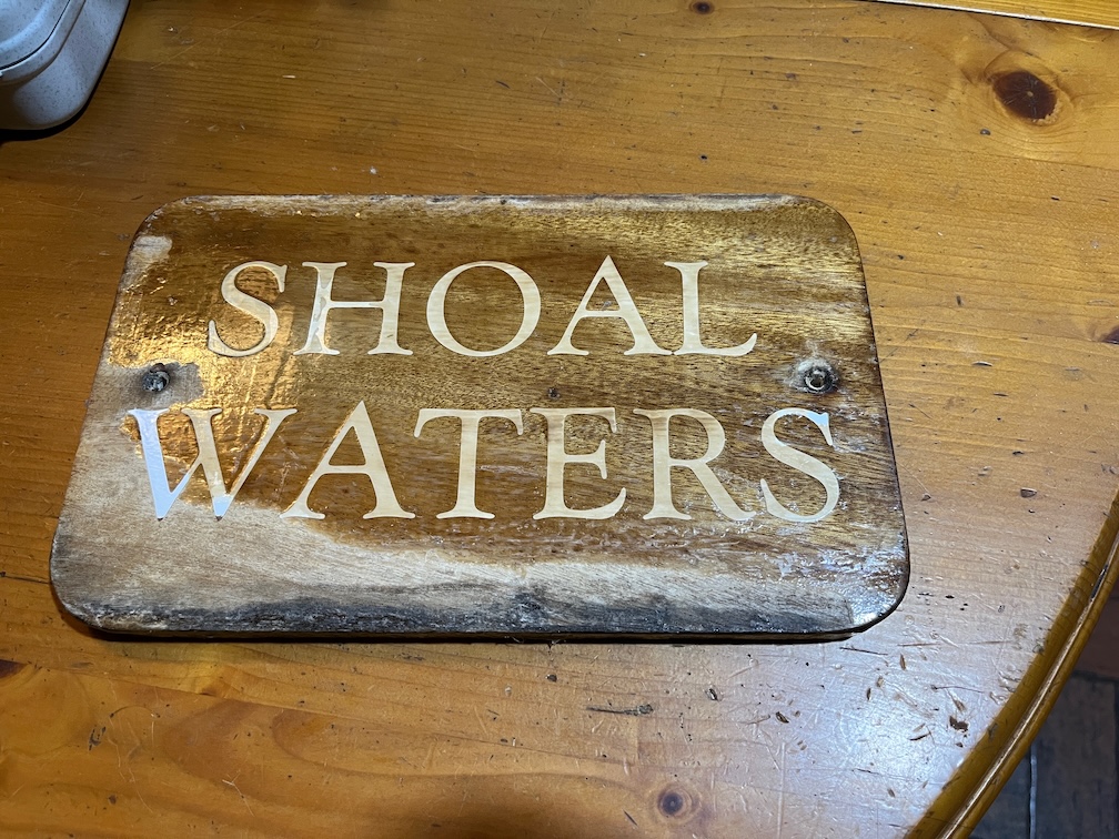
This is a section from a photo of Shoal Waters whilst she was still in the ownership of Charles Stock and you can see a large discoloured area to the left of the name board that corresponds to the repair in the photo I took this morning.
So, more tasks to add to the list. Remove any remaining varish, sand and fill the two, possibly three areas that need graving pieces. Carry out some stain removal to at least lighten the darkened wood. Then I will probably stain the entire transom just to stop it looking such a light colour and after that, we shall see.
Sa far an interesting morning.
Time for a cup of tea.
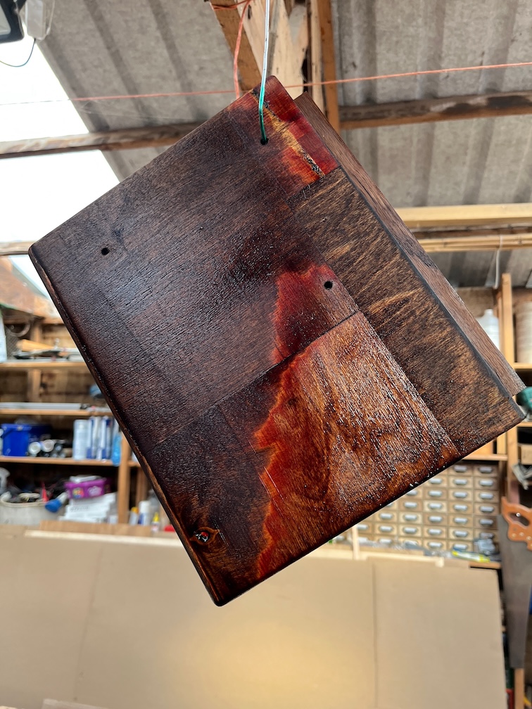
During my next break I sanded the transom with 180 grit sandpaper and then went tapping around to see where the soft returns were.
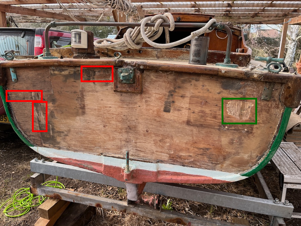
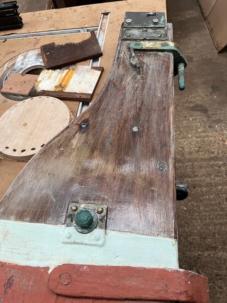
The green area is where I’ll certainly put a graving piece and the red areas show where I’m getting soft returns with my tapping. The top red area is a place where I’m tempted to put another graving piece rather than use the epoxy sealer. One or two of the very darkened areas of wood I’ll treat with Oxalic acid and try to bleach the wood a little, but other than that I think the transom will be lightly stained to even out the discolouring and then varnished. This will not hide the repairs and such, but they will be less noticable unlike with the varnish/paint which hid everything.
The two red area on the left will be left until Shoal Waters is next out of the water for maintenance and I can spend more time investigating and repairing.
The weather this morning was a little warmer than yesterday, but even so, the day started in much the same fashion as previous days, varnishing.
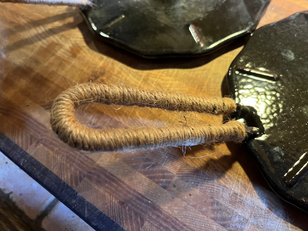
The first small task was to insulate the flame spreader handle. This handle is not left on the spreader when in use but used to remove the spreader when hot. Unfortunately, the bare handle becomes very hot very quickly and without care a burnt hand results. This insulation consists of 6 mm round stove rope threaded onto the handle, glued at the ends with seal adhesive and then, when the adhesive had dried, cotton string was wound over the stove rope creating the handle you see. This resists burning and insulates the handle well enough to be able to use it on a hot spreader without burning skin in the process.
The spreader fits well on the galley stove but I now need to find somewhere to stow the spreader and handle.
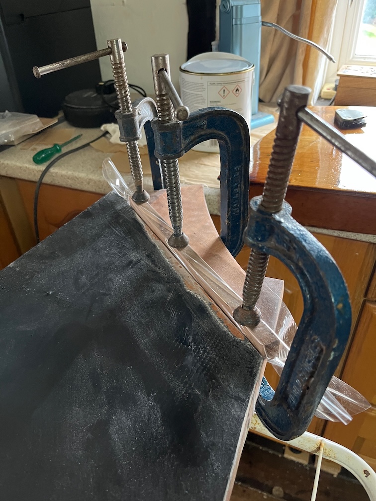
The next task was to repair the port centerplate case side that was damaged yesterday. I have clamped a small batten of wood encased in film up agains the edge where the repair is required.
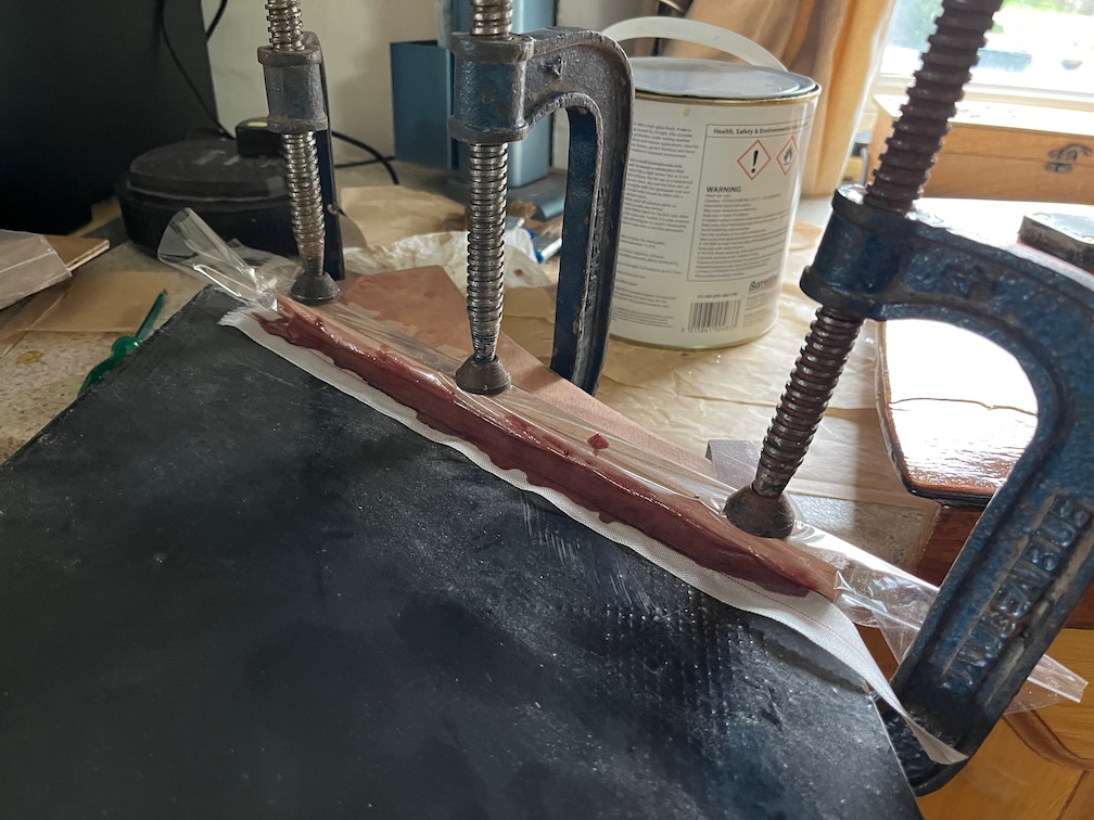
Epoxy lightly thickened with low-density filler was dripped into the damages area and peel ply applied. I used the fast hardener as it was a simple application and I did not need the extended pot life of hte slow hardener.
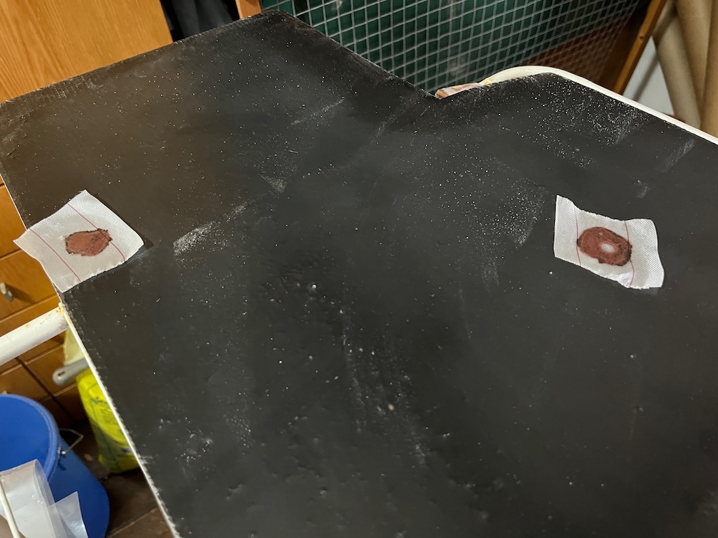
There were also two other spots where the glass mat was slightly exposed and were treated similarly. Once the epoxy has cured all three areas will be lightly sanded to the same level as the surrounding epoxy.
Another small task was to rummage through the various boat bits I have around the places for two cleats to put on the boom for the luff reefing lines. I did have some but they were far too small for the job, so suitable ones are on order.
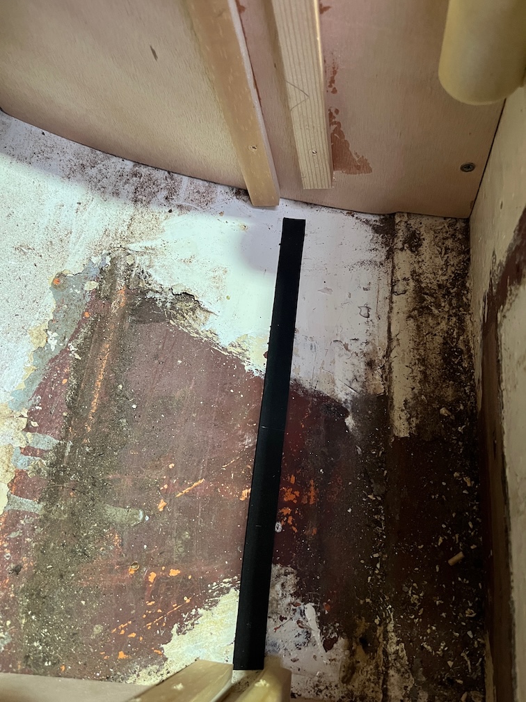
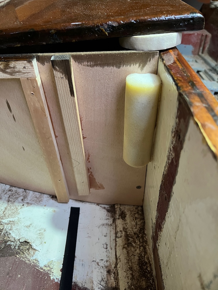
To complete the galley stove locker I put in place some chafe and clink prevention.
I put a length of sticky-back neoprene tape on the bottom of the locker where the edge of the stove board or the lid will rest. This is the chafe protection.
Then I used some very sticky double sided sticking tape to fix a small foam paint roller in the corner of the locker and this is the clink protection.
When the stove is stowed the foam roller prevents the lid of the stove opening and closing, going clink against the locker or against the stove itself every time the boat rocks with a wave. I know this from experience of living aboard a sailing boat for ten years. There’s absolutely nothing so annoying as something going clink, clink, clink, clink whilst you are trying to sleep. Whether it be pots, pans, crockery, loose tools, it doesn’t matter, it is infuriating !!!
Anyway, that completes the galley stove and locker task.
The next small task is to remove the Maldon sign on the transom.
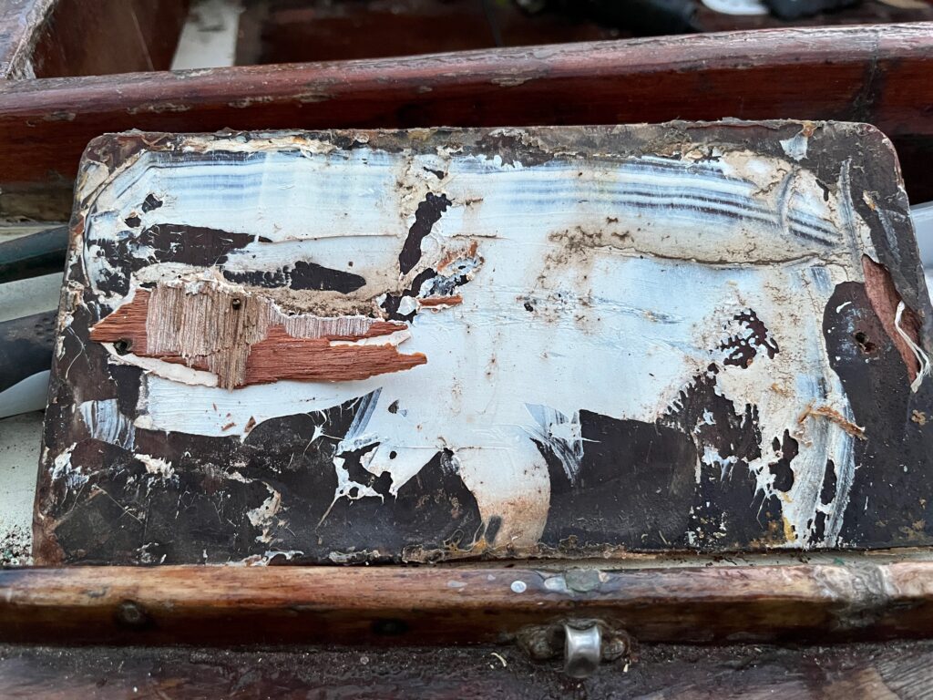
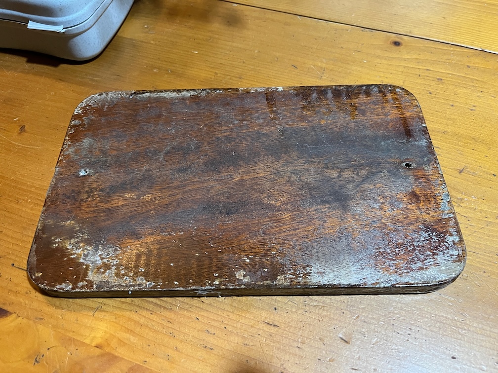
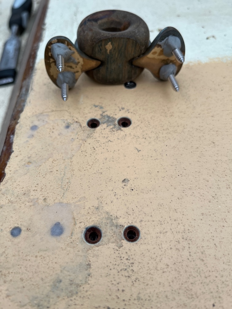
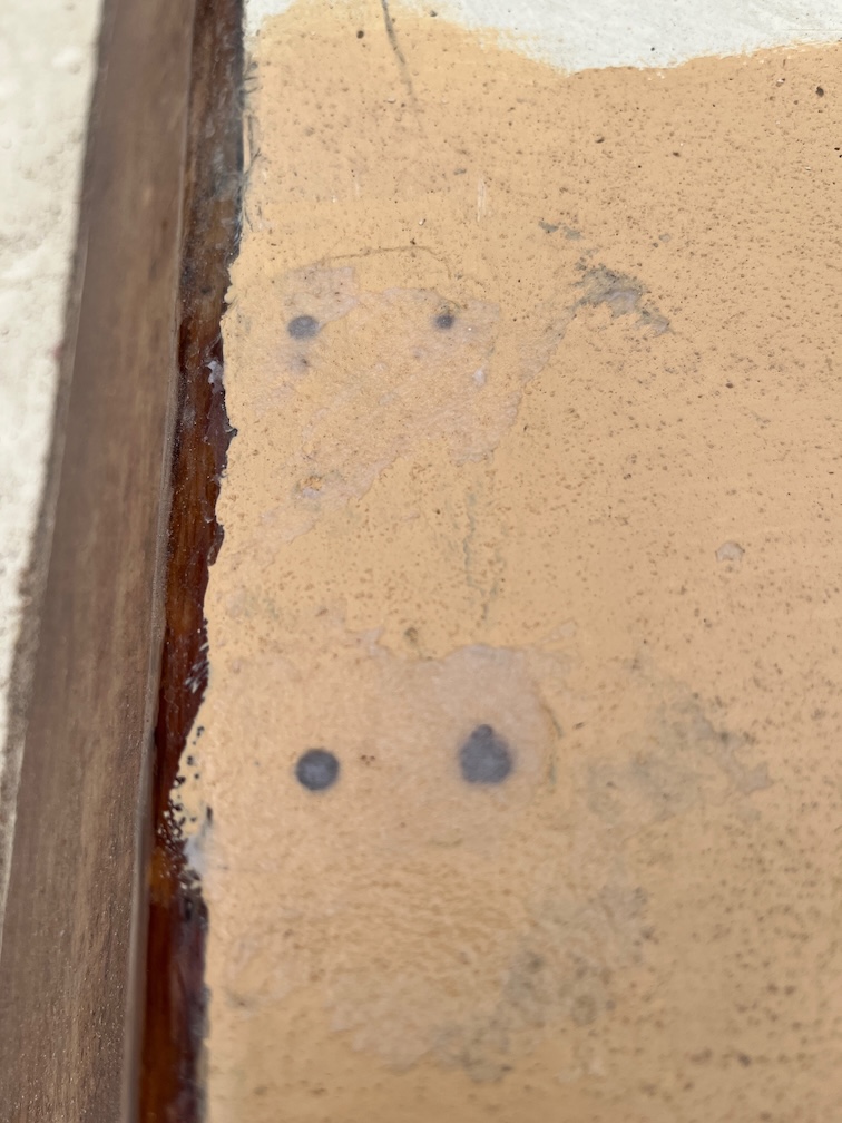
This is the back of the sign and you can see that some of the transom has pulled off with the sign. This sign is marine plywood and was glued in place with a sealer adhesive and a very good one at that.Too good, as it turns out.
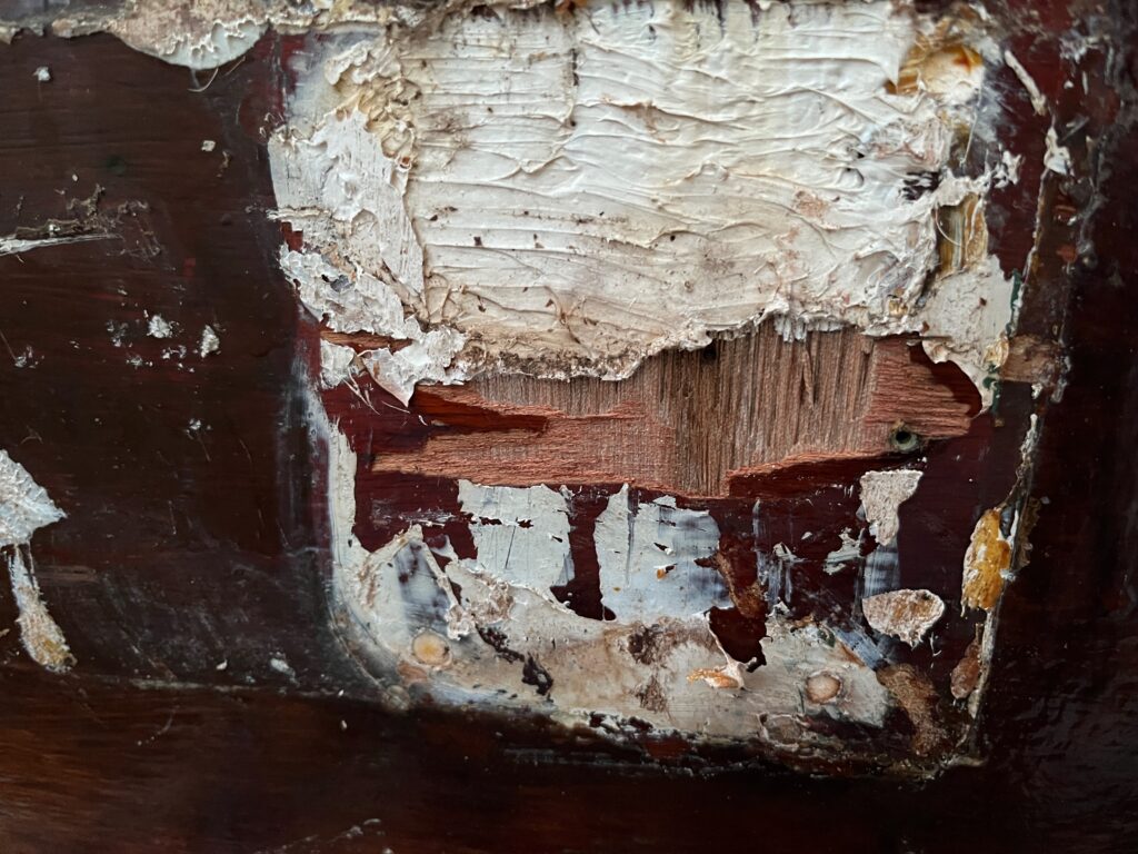
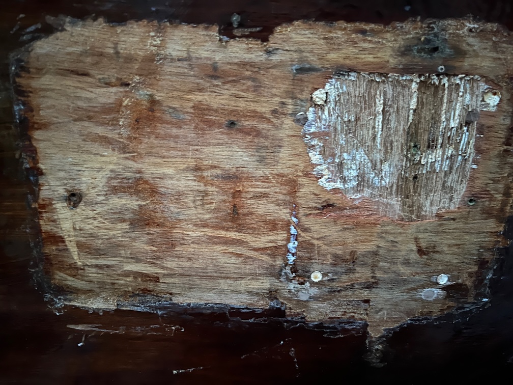
Here you can see the area on the transom that was pulled off. You’ll note that there appears to be three holes in the transom, two at the bottom and one at the top right. I would presume that there is fourth under the white stuff. Armed with a heat gun and scraper I got rid of all the sealant and the brown paint/varnish.
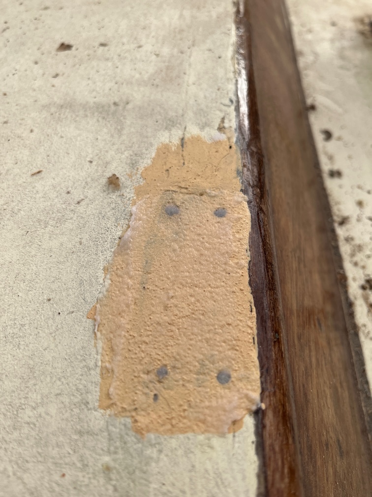
Here is the result. there was indeed a fourth hole but it also looks like that large area of white sealant also filled in an area that was damaged. You can see the vertical grain of the plywood that is under the outer layer, so there seems to have been some older damage to the transom in this area.
I recall that for the first year that Tony Smith owned Shoal Waters, he mounted what looks like a long shaft seagull outboard motor in the stern and I wonder if these holes and damage were something to do with that. Not that it matters, the thing is how far down the rabbit hole do I want to go with the repair? The simplest and easiest way to deal with this is to fill it with sealant again, a non-adhesive type, since it is under the Maldon sign and will not be noticeable. The correct way to fix this is to insert a graving piece by cutting a shallow recess where the damage is now, I’d make this 6 mm deep as that is the thickness of the marine plywood I have, then cut out a piece of plywood that fits into the recess and glue it in.
My first inclination is to do it properly, but I recall that there is a soft area on the transom on the port side that needs looking at, so I am really tempted to scrape the layers of paint and varnish off the transom entirely, it comes off really easily, and to see if there are other areas that need to be dealt with and do them all at once.
Something to think about.
The final task for the day, for which I do not have photos, was to clean up the slot and top of the keel. Mostly this meant removing any loose glue by sanding and then prising it off with a chisel. Quite a lot is on very securely and rather than risk damaging the wood by forcing it off, I’m going to leave it on. The sides of the entire slot was sanded with 120 grit sandpaper as was the top of the slot. I also cleaned up the front face of the aft block and found another soft spot. This was about the size of the thimble and I excavated it with a chisel blade. Before I assemble the case properly this area, as well as the two soft spots on the hull, will be liberally coated with the penetrating epoxy. The thimble sized hole itself will then be filled with thickened epoxy.
It is a miserable day today, here in the Fens of Norfolk. It has been sleeting sideways for the last couple of hours and it cold, just 2º C. Still, most of the tasks for today are in the workshop out of the wind and rain.
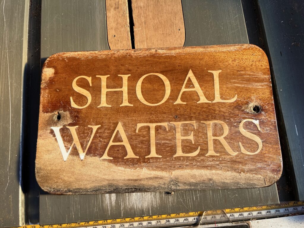
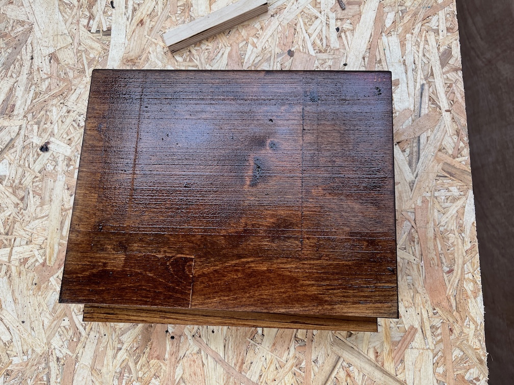
First up is the name board.
This is the board vanished on the front..
But not on the back. The varnish you can see here has come from being varnished in place on the transom. The trouble is that having no varnish on the back has caused the wood to warp and with screws in the middle of the sides instead of on the four corners, the warp has pulled the top and bottom away from the transom and varnish has seeped down behind the sign.
So, to carve the name I had to first un-warp the board. It’s currently resting on the Rayburn, varnish side up and is starting to get flatter.
Next I took sandpaper and scraper to the rudder stock for a little energetic work to warm me up.
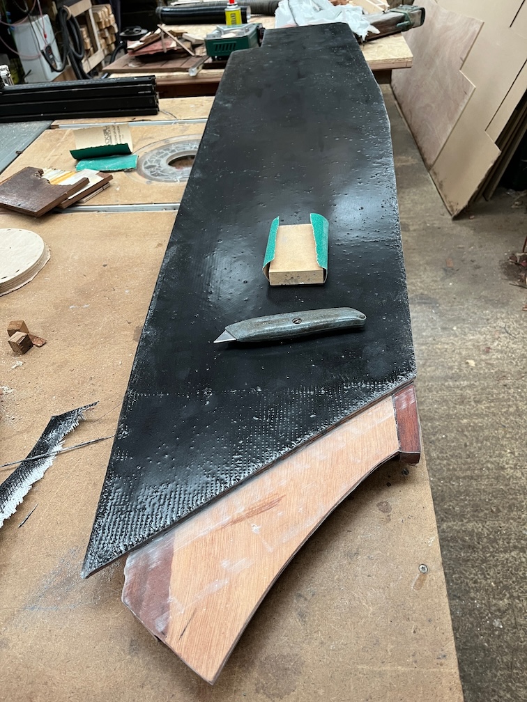
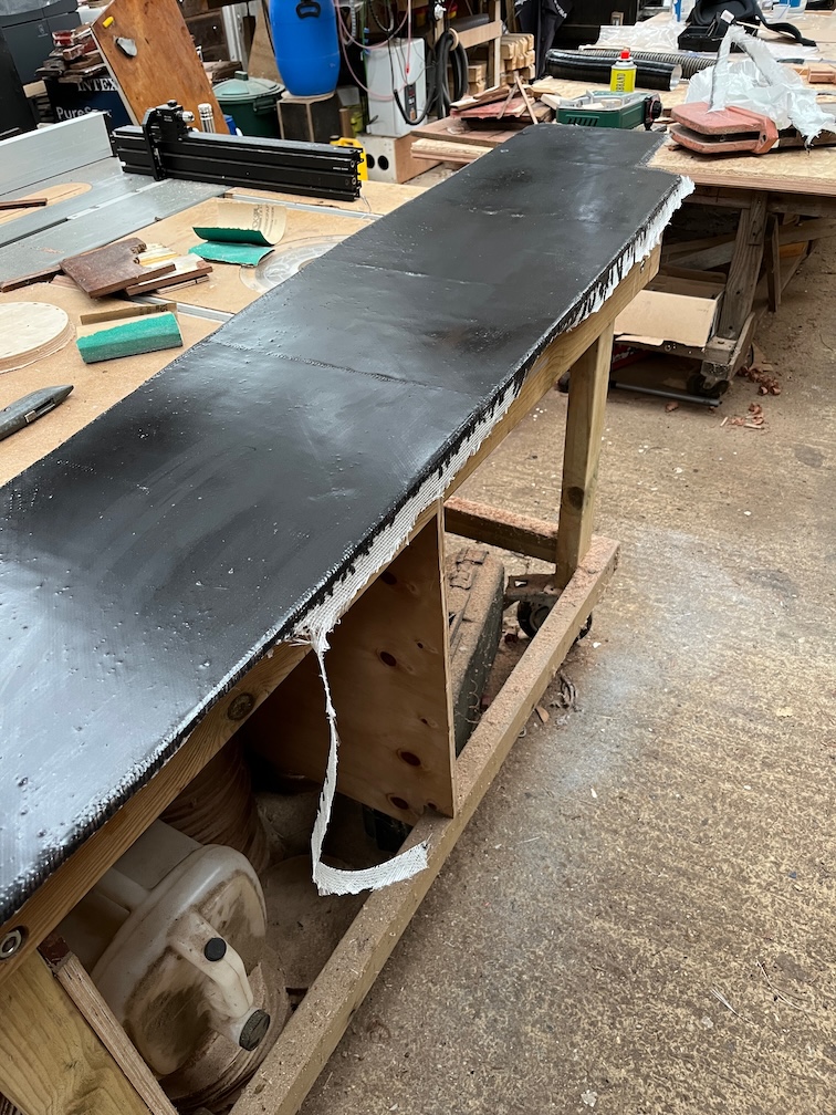
Next, trimming the excess glass mat and epoxy from the case sides. This one worked well.
The port side not so well. The trimming and sanding around three of the edges came out correctly.
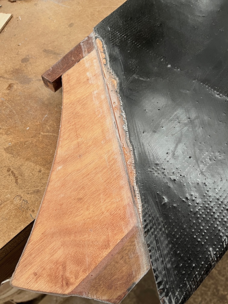
But I screwed up when putting the peel ply on the aft section here and it overlapped the inside face where it should not and I had to cut away the glass matt to get it all out. It’s not too much of a problem, I’ll just have to mix up some epoxy and patch the gap.
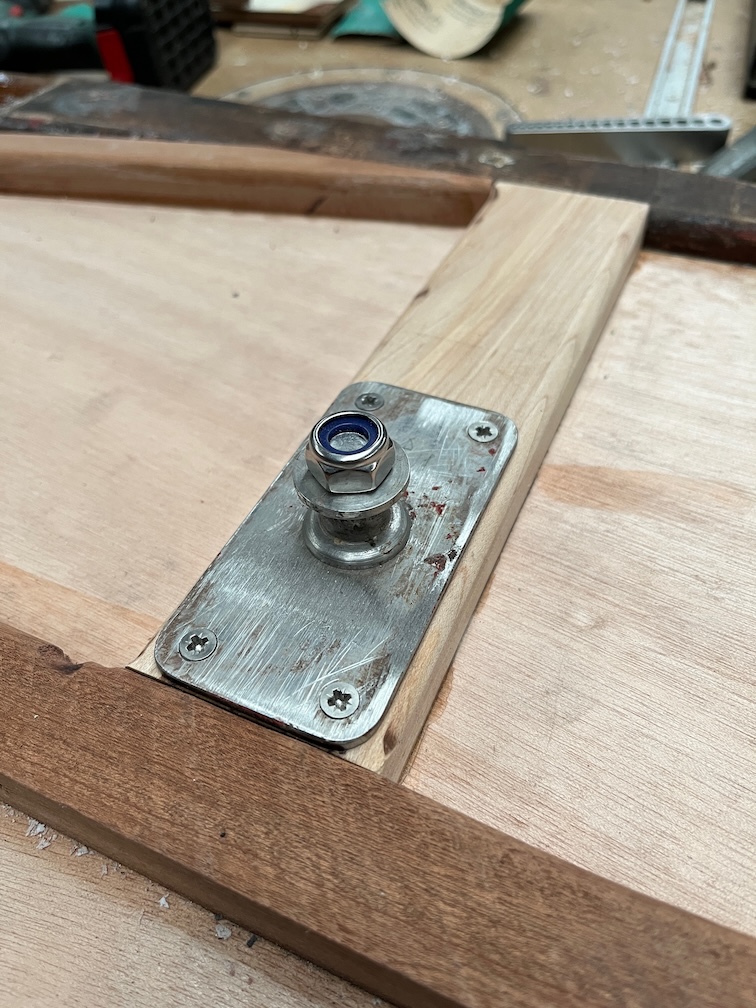
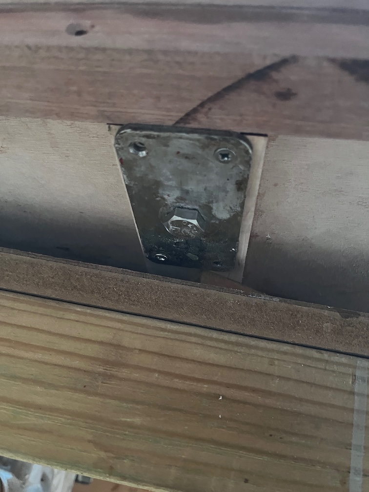
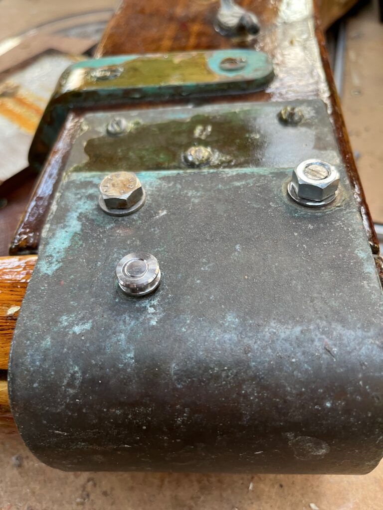
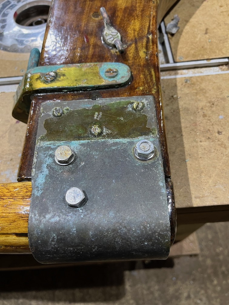
In the meantime, I drilled out the pivot bolt holes, put the case sides together inner face to inner face, put the metal plates on the stiffeners and put the bolt in place with the spacer on the outside. As you can see, the bolt is about 5mm too short ! It has to be long enough to screw through the nylon locking ring, it is not called nyloc for nothing, or be long enough to allow a lock nut.
So, one 10mm longer is on order. This one will do for the next phases, the dry fit possibly even the real fitting, but the longer one will be needed before the boat goes into the water. There will be six layers of sealant, two either side of the spacer and one each under the metal plates and one on the outside of each plate and under the bolt head on one side and the nut on the other. All those sealant layers will probably mean that the shorter bolt may not fit. I have M10 studding from which I can cut a longer bolt but since it is mild steel it will only be good enough for the assembly.
Still, not having the correct bolt will not stop progress.
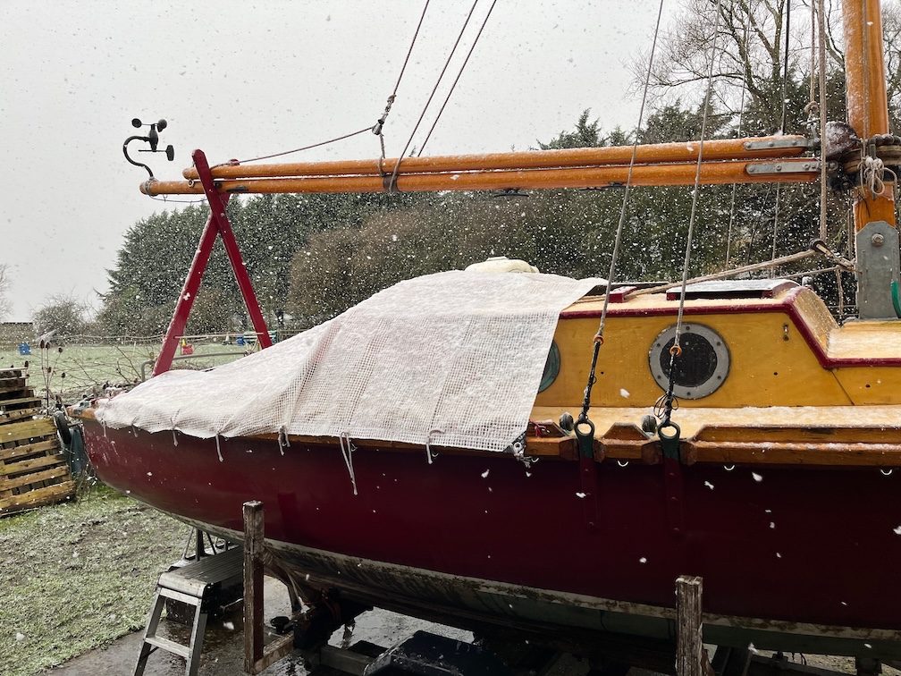
It has stopped sleeting and is now snowing. Still cold.
Makes one glad for a workshop.
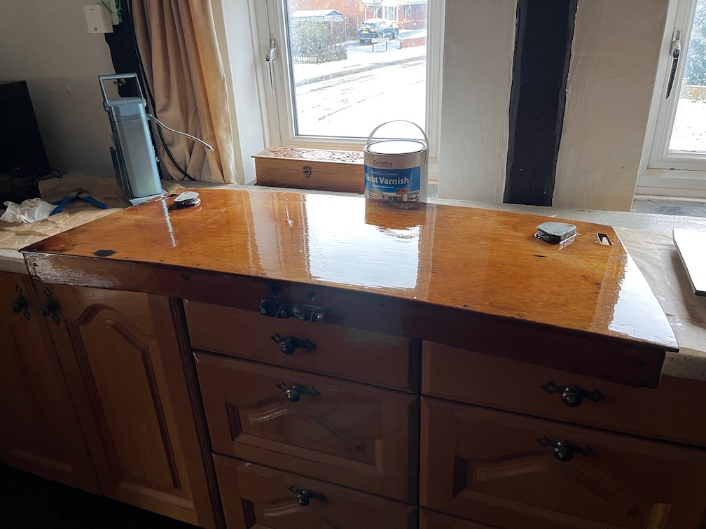
Since I have the poop deck removed I decided to continue the theme of getting ahead of the brightwork where possible and give it a coat or two. I was sanded in the workshop, brushed off and then brought into the workroom for its first coat of varnish. Being an outside piece of varnish it needed a good sanding but has come up nicely as a result. This might only need two coats. I might put more on, after all it is going to be out in all weathers when sailing and under a piece of canvas when on the mooring, so more coats of varnish will be better than less.
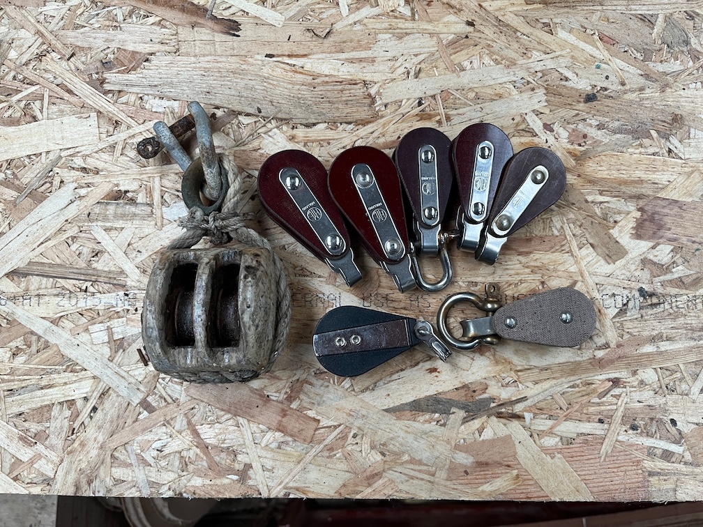
One of the things on my list of upgrades for Shoal Waters in the future is to replace all her old blocks with new ones. In the meantime I will replace the old blocks with Tufnol blocks that I have left over from building Naiad.
Shoal Waters’ blocks are currently like the one on the left and the spare ones I have are the others. I say spare but the fact of the matter is that I ordered exactly enough blocks to dress Naiad’s mast, the five new looking blocks on the top row. But they didn’t arrive. After a month or so I got back to the supplier and asked what had happened and they had no record of the order being fulfilled, so they sent out a new set of blocks which arrived within a few days. All well and good. Naiad was launched and I thought nothing more about it until about nine months later when the original set of blocks arrived in the post.
I contacted the supplier and they said that since they still didn’t have a record of those being fulfilled and dispatched I was free to keep them. They have been sitting in my rigging kit box for the last seven years!
So, Shoal Waters will have her existing block replaced by these Tufnol blocks and I’ll make some shiny new wooden ones for another season.
For now, since it is Sunday and I have already carried out a number of tasks, I shall call it a day and rest for the remainder of the afternoon and evenong.
A slight change to the procedure today, it was 1º C when I first went down to the boat this morning and there’s no way that it is suitable to apply varnish. So I turned on the heater and took a look at the work I did yesterday.
Having removed the cramps and such I tested the epoxy with a fingernail and found that it was quite solid. It seems that the heater arrangement worked well.
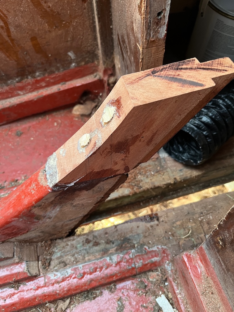
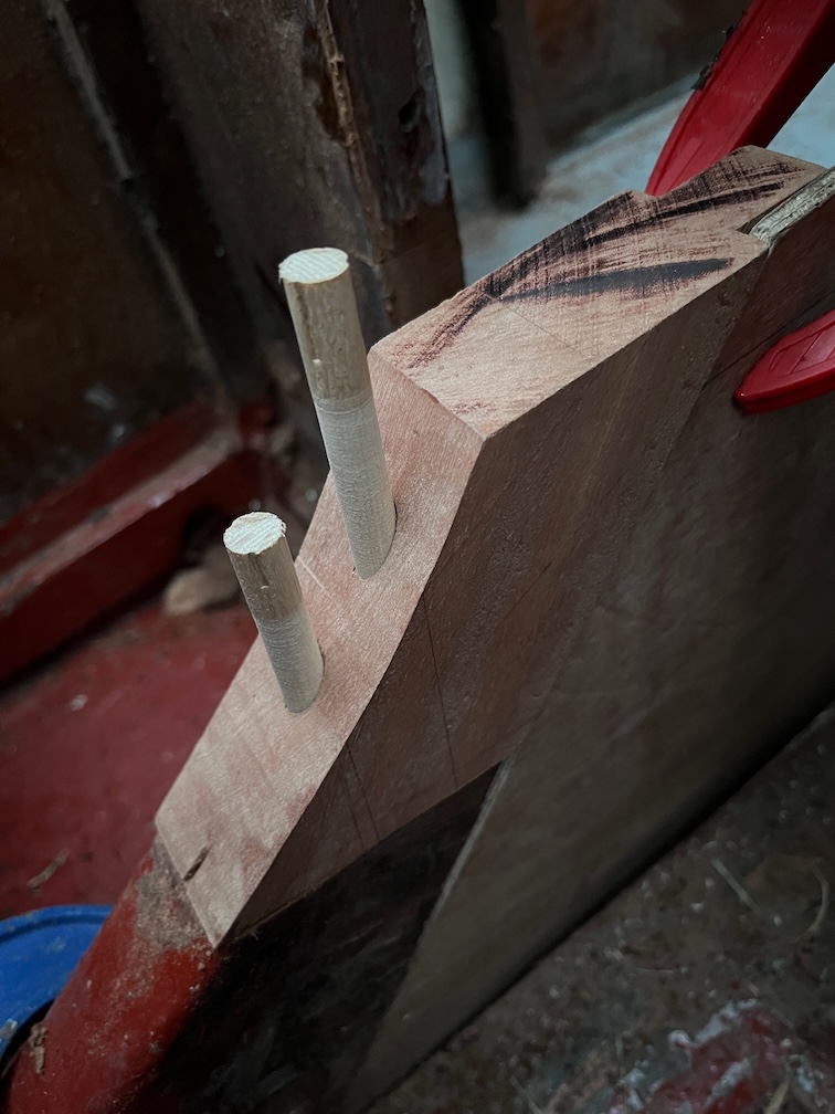
I trimmed off the tops of the pins and the did not break the top off the block, so I will presume for the moment that it is well stuck.
Time to clear the area for the next task.
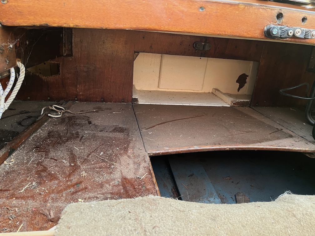
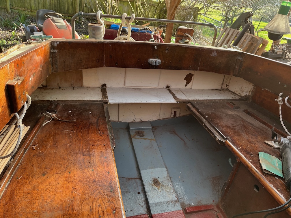
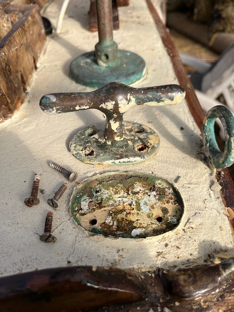
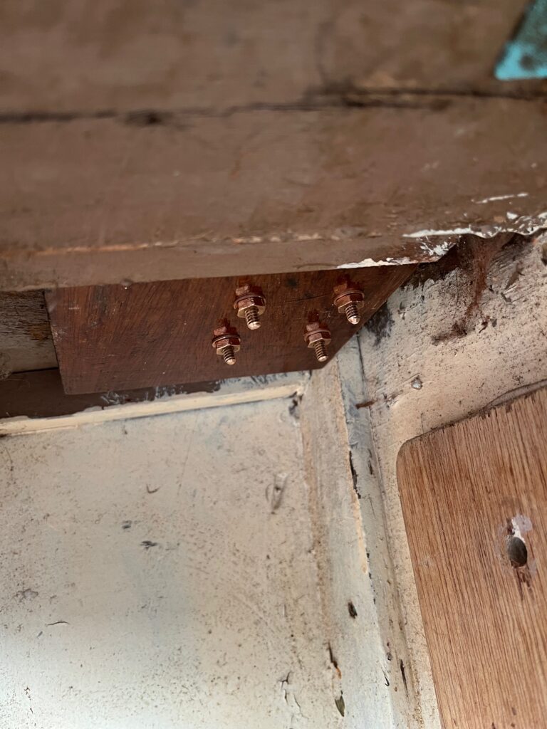
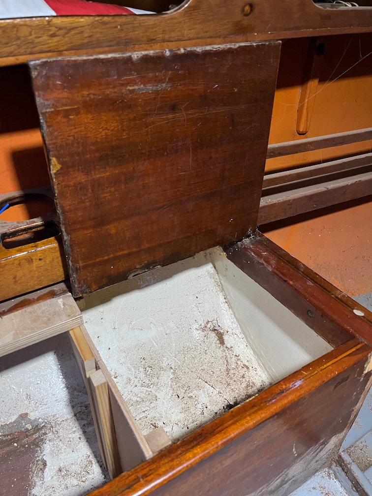
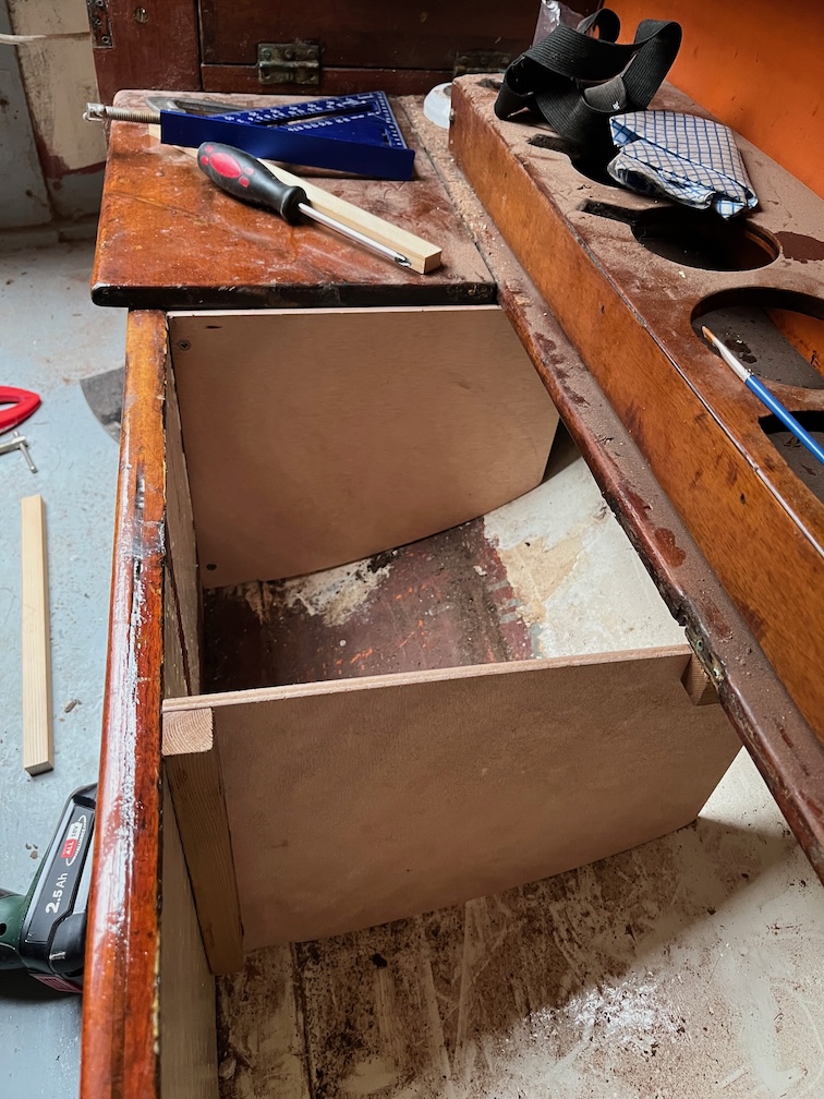
This is the area under the poop deck and you can see the lockers that occupy the space under the aft deck. This is pretty useless as is in order to get at anything in these lockers you need to clear out everything under the poop deck, or remove the poop deck.
I would have left these untouched but the surveyor noted:
…the two bronze cleats aft are only screw fastened to the thin plywood deck; without any wooden blockings below. Recommendations: Ensure the aft bronze mooring cleats are securely mounted.
The access to these cleats is via the locakers and that is not going to be easy. So, I elected to remove these lockers which will not only allow backing pads to be placed under the cleats but easier access to the otherwise awkward space.
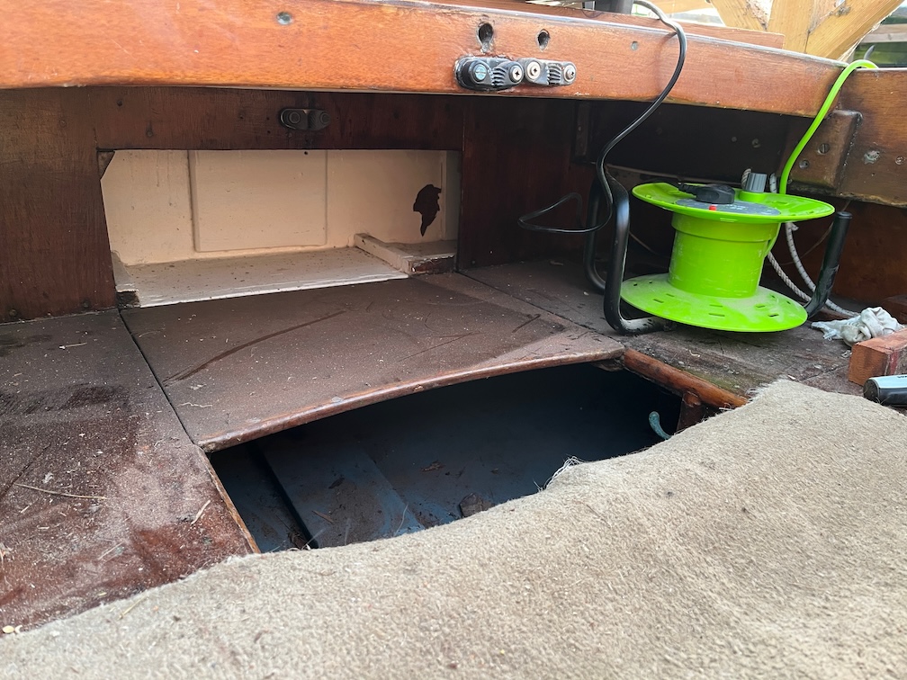
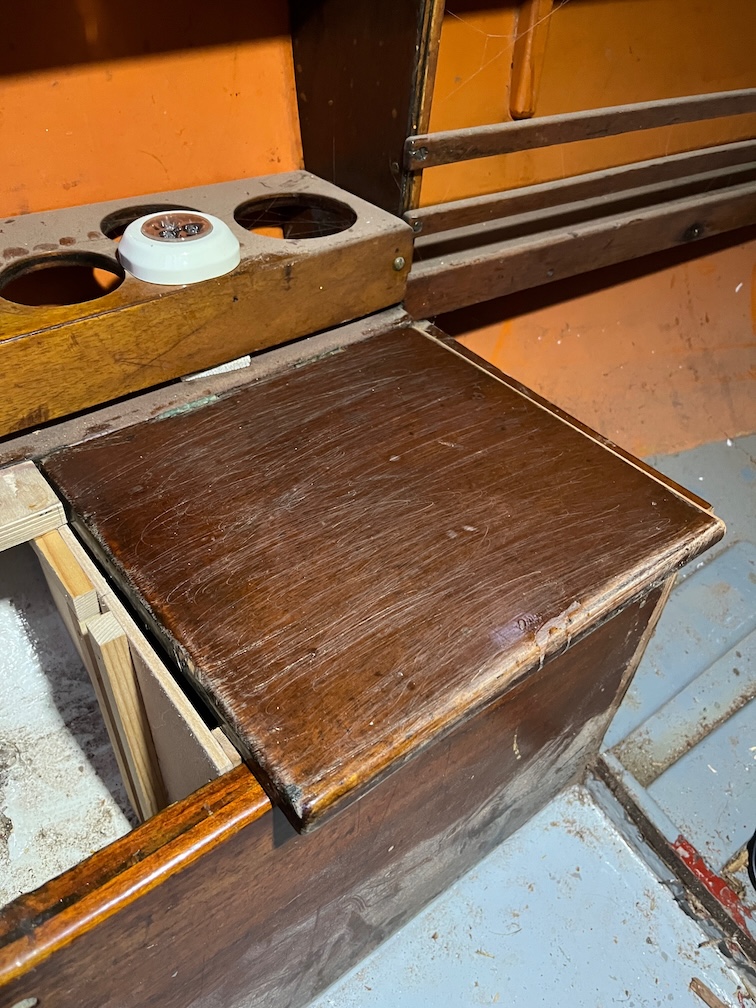
The area under the poop and aft decks is quite spacious.
There is even more space once the locker fronts are removed. This space is now usable.
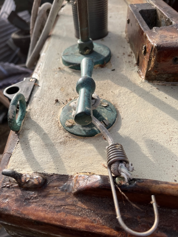
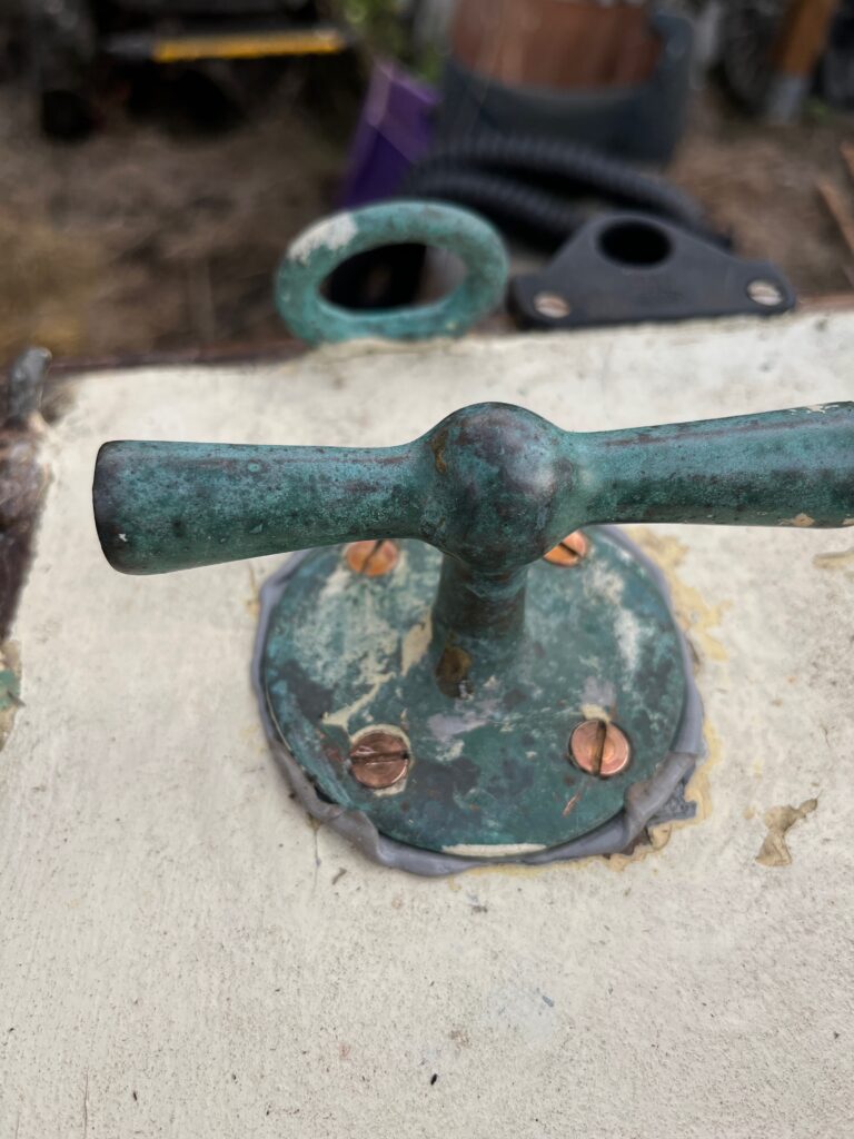
The next part of the task is to remove the cleats. This one has a wellie hook.
Here’s what Charles has to say about wellington boots:
I use traditional knee length wellington boots for mud work. They need to fit well so that they do not stay behind in the mud as you walk forward. One minor irritation, especially for knock-kneed sailors is that mud on the inner side of each boot will transfer from one boot to the other as you walk, rising higher each time and getting onto the inner side of your trouser legs above knee level. This means mud on board and in the cabin. The answer is to walk slightly ‘Frankenstein’ fashion, preventing the boots from touching. Whatever you do when working in mud, some will stick to your clothing. Do not try to rub if off wet for it will only stick harder. Leave it to dry when it will brush off cleanly. Once boots have been in the mud they are not welcome on board until cleaned, but this cannot be done without water. Don’t leave them stuck in the mud alongside the boat for they will float off very quickly as the tide returns. Tie them to a cleat (see fig. 5). I use a piece of shock cord with hooks at each end. Once wellingtons came with holes punched in them at the back just below the lip, presumably to tie them together in pairs. Since the advent of packaging in hygienic boxes such holes are missing but the office punch will suffice.
Sailing Just for Fun pp 57-58
Anyway, the hook is in the way and needs to come off.
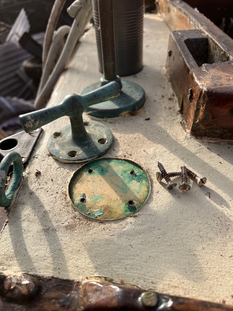
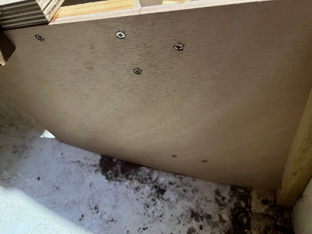
The screws in this cleat have been replaced with stainless steel screws, a sure sign that the originals were brass and dezinced to the point of being useless.
The screws came out easily, thankfully, which is not surprising when you consider that they are just into 3/8″ plywood.
Similarly, the screws came out easily on the port side. Now to make the backing pads.
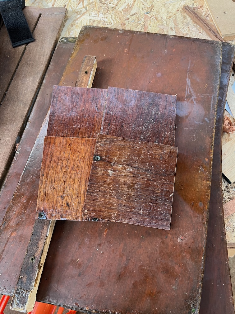
I cut the removed fronts of the aft lockers into four 120mm square pieces…
…and glued them together with the varnished side outwards.
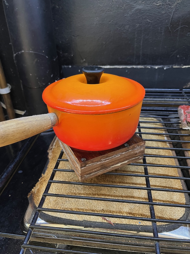
It was still sufficiently cold to make the glue drying time long, so into the house they went to be placed on the Rayburn with a pot on top as a weight.
Since I hd a little bit of time I decided to try and locate the ‘soft return’ that was reported by the surveyor on the port bow.
This is it here, I think. Here’s a short video of me tapping.
I think you can hear the difference in the sound return from the good and soft wood.
I’ve sanded the paint a bit to tidy up the area and once the wood has dried I’ll apply so of that penetrating epoxy I keep going on about. The same for the transom, if I can find the soft spots.
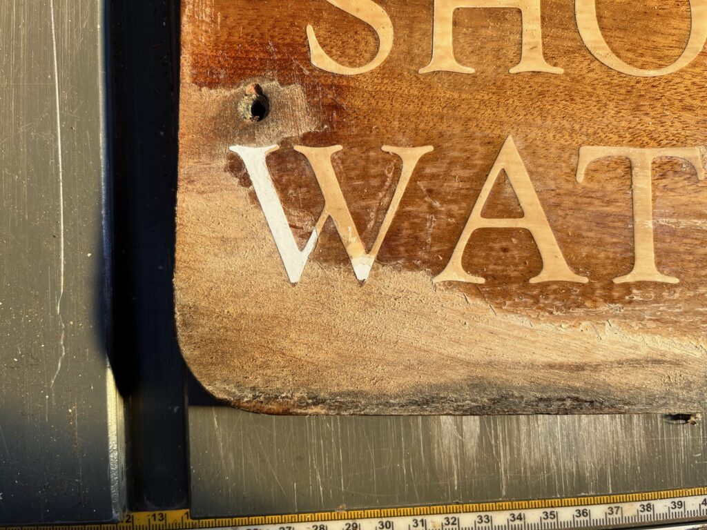
The name plate on the stern is looking a bit ragged so I took it off and sanded and scraped a bit. The trouble is that the letters are a vinyl transfer, as far as I can see and sanding is going to sand off the vinyl as well.
You can see that happening on the bottom of the ‘W’.
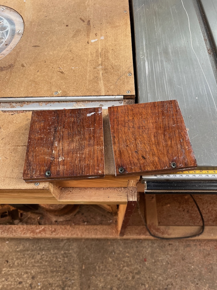
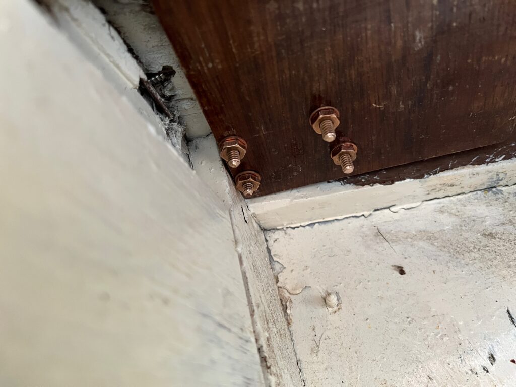
Time to move on with the cleat backing pads. It was a bit tricky but eventually I got the bolts cut to length, the butyl tape applied and the backing pads in place. This is the starboard one…
And this is the port side. The bolts came out very close to the edge of the pad, but that is due to the location of the cleat on the deck.
The starboard cleat from the top. The squeezed out butyl will be removed later.
The port side cleat had a bit more butyl tape under the cleat so there is more oozing out.
The drop nose pin arrived in the post this afternoon and I didn’t waste any time trying it out.
The is the other side and the head has a groove running around the circumference for attaching a light line.
The tiller was a tight fit, mostly due to excessive build up of varnish, so I took it over to the belt sander and slimmed it down a little.
I had to take more off than required as needed to varnish the now bare wood.
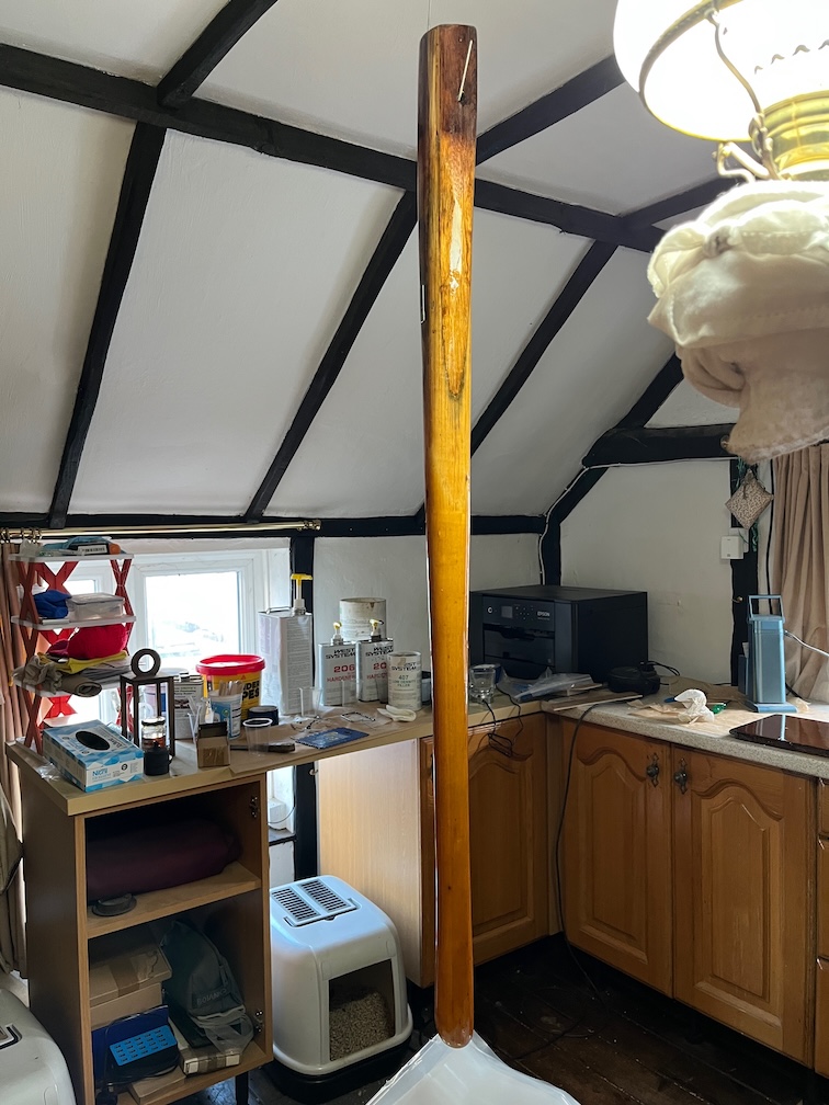
This does seem to be a very nice piece of wood and as far as I can tell, it is the original tiller that Charles put into Shoal Waters back in 1963. Every photo I have of the boat around that time shows this as the tiller. I wonder if this came from Charles’ previous boat the Zephyr? I know he took a lot of the gear out of the Zephyr and used it in Shoal Waters, but whether the tiller was part of that I don’t know.
Still, it is at least 63 years old and in near perfect condition.
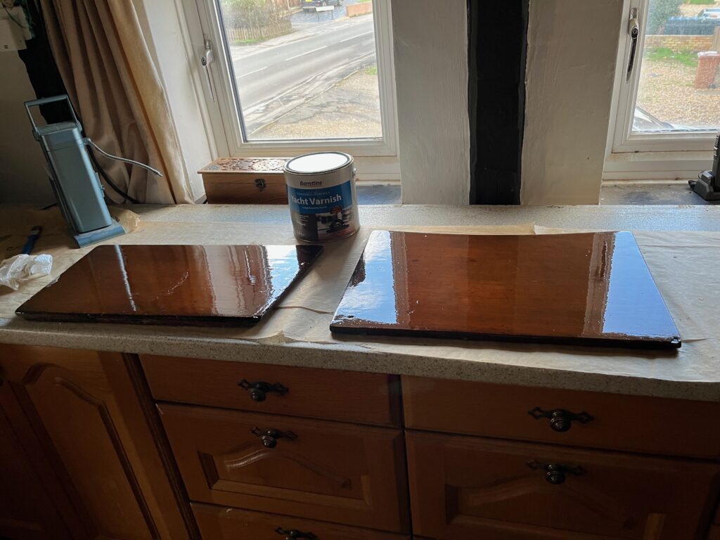
Hanging from the beams in the workroom with a coat of varnish. I lightly sanded the existing varnish prior to applying fresh.
I also washed these two boards with white spirit, lightly sanded and applied varnish. The board on the left is the bottom washboard, and the other is the board that goes between the two thwarts under the poop deck. A second coat of varnish was applied in the cabin, so that is also coming along.
It was a great day. The sun shone and despite a cold start to the day it soon warmed up to a balmy 7º C. There was little or no wind and I managed to get a lot of things done and ticked off the list.
All that remains of the major construction efforts are the fitting of the centerplate case and whilst that is not a simple task, it is not difficult. It is, however, just a tad daunting. Making it completely watertight and strong is critical to not having the boat sink when launched !
As is now usual the first task before work was to apply some varnish to two small areas in the boat, the back of the new galley locker and the cut side of the forward locker lid.
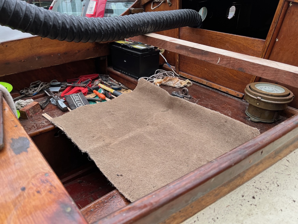
After that I turned the heater on, pointed the end of the hot air duct towards the existing aft block, covered the cockpit footwell with a piece of carpet and left it running for a couple of hours.
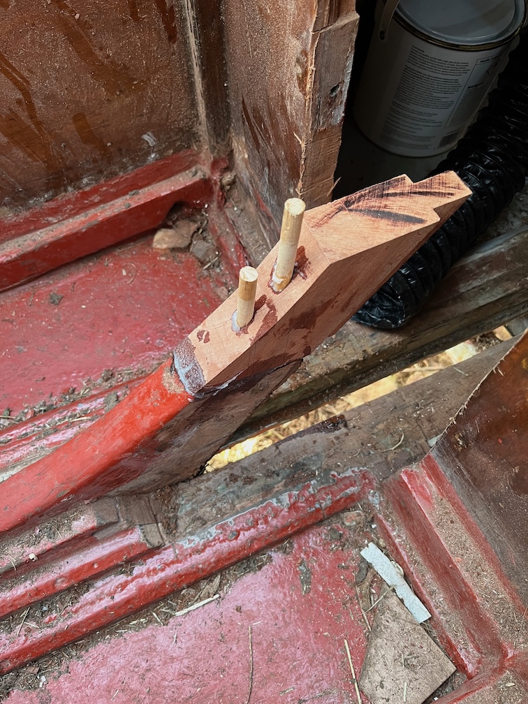
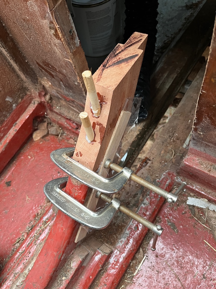
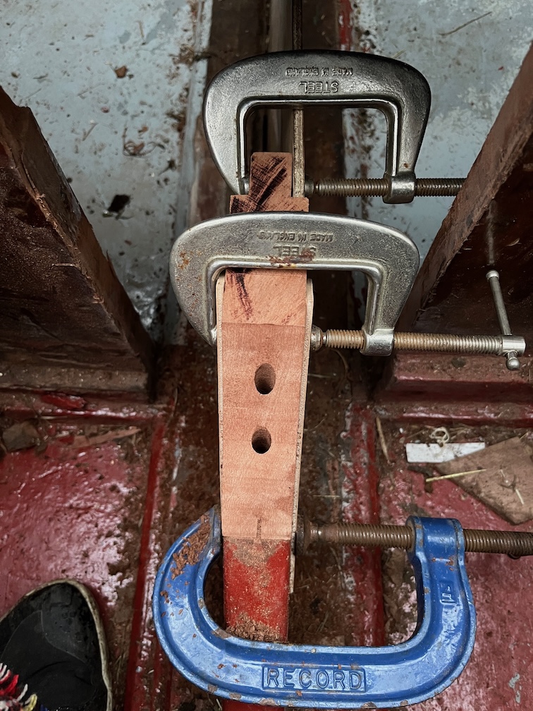
During my morning tea-break I applied neat epoxy to the top of the aft block, now well warmed up, and to the bottom of the new piece, also warmed up by being on the Rayburn all night, then added some thickener to the remaining epoxy, spread some of this onto the bottom of the new piece, and took thickened epoxy, top and pins down to the boat.
The pins were put into the top section and allowed to protrude an inch or so to make locating the top easier. The new section was put in position and the pins tapped into their holes fully. After a little cleanup of the squeezed out epoxy I clamped two thin pieces of wood on either side of the block, each having plastic film wrapped around them as I do not want them to stick to the block. After that I replaced the carpet over the footwell and hopefully, even on its lowest setting, it will be enough to keep the wood and epoxy warm enough to cure properly.
I’ll leave the heater running for most of the day and then evening to give the epoxy time enough to begin the cure process.
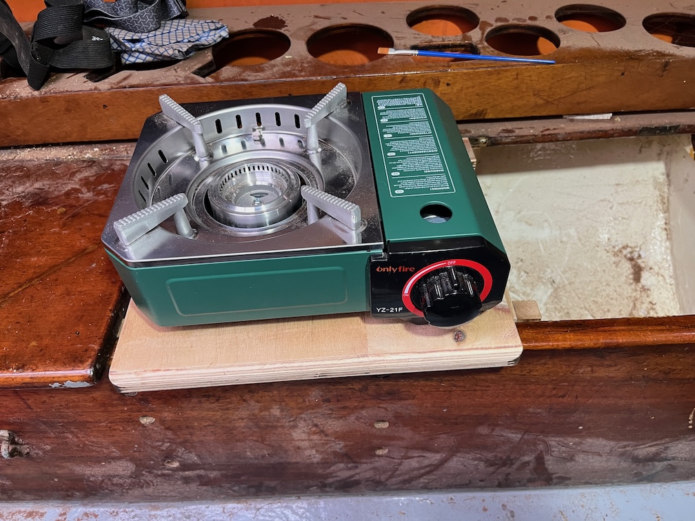
While I was down at the workshop and still had break time left, I bolted the galley stove to the support board and the galley stove task is completed.
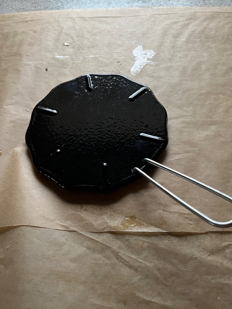
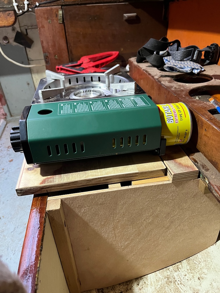
I had a useful arrival for Shoal Waters just before lunch, a cast iron flame spreader.
This is the item and a very useful device it is for portable gas stoves (PGS). You see, the main problem with cooking on a PGS is that you tend to use camping or hiking pots and pans, usually made of aluminium of stainless steel, but all very thin metal.
Okay, so I do have a medium sized cast iron frying pan on Naiad, but that’s beside the point.
The issue is that it is unbelievably easy to burn everything, the thin base of the pots does not conduct the heat away from the flame much, so you get a very hot spot in the centre of the pan and a much cooler area around the edges.
Try cooking porridge on a PGS in a thin bottomed pot and you’ll soon see what I mean.
This also happens with the alcohol burner stove I have on Naiad and I have one of these flame spreaders on her as well.
The flame spreader does just exactly what it says with the result that you get a pretty evenly spread heat right across the 170 mm diameter of the spreader. I have found that it really works well on Naiad and since I like porridge, I got one for Shoal Waters as well.
There are three problems with it. Firstly, it takes a bit longer to start cooking since you have to heat up the spreader first. Secondly, it gets hot enough to scorch wood so you need to leave it on the stove until it is cool. Thirdly, the handle, which you take off when using the spreader, gets hot very quickly when you put it into the spreader to lift it off the stove, hand burning hot. I’ll see if I can make some kind of heat resistant covering for the handle.
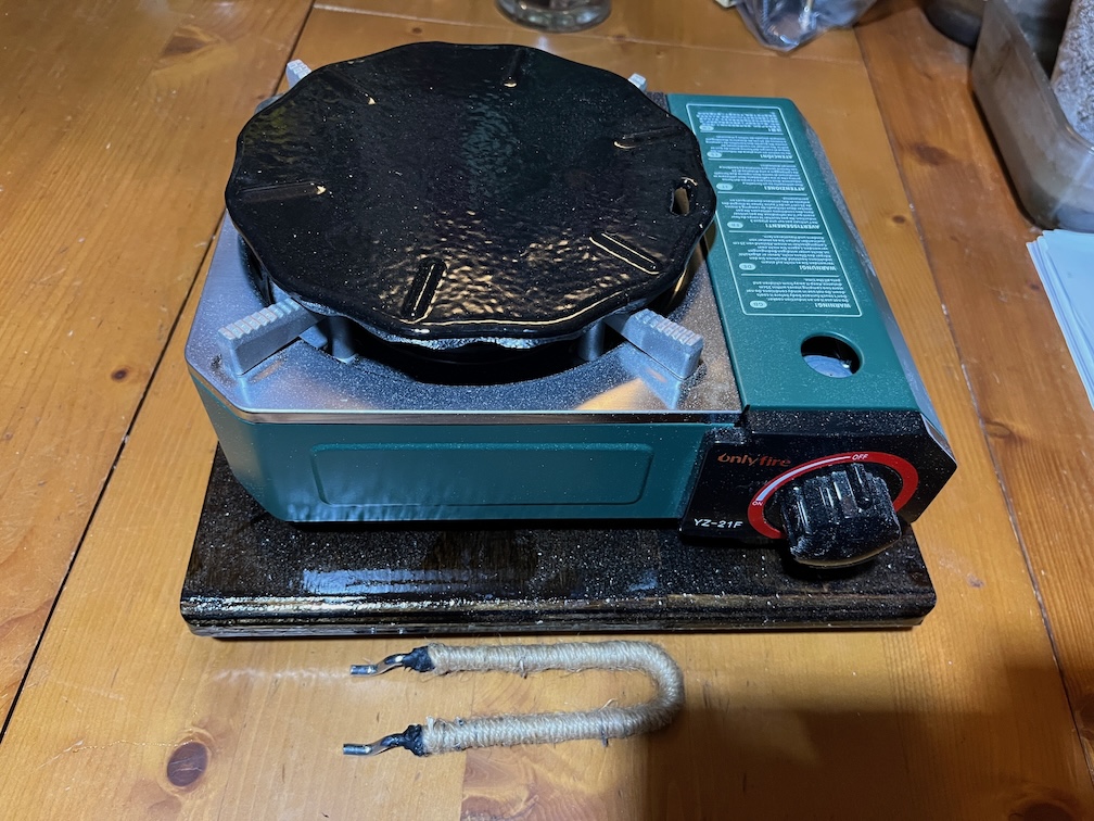
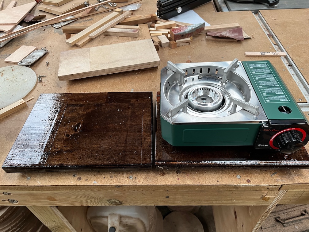
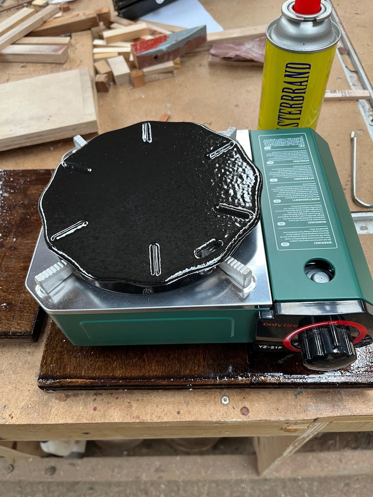
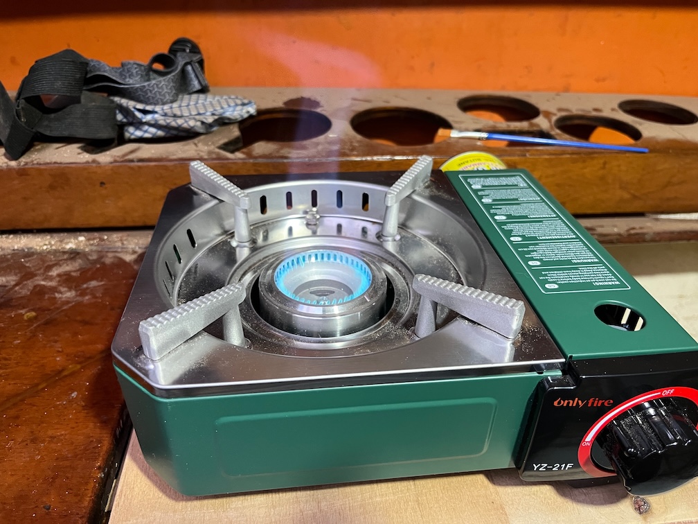
It is a great fit on Shoal Waters’ new gas stove, as you can see.
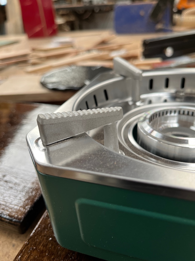
The pot holders on this stove are stepped and this makes the stove top fairly non-slip.
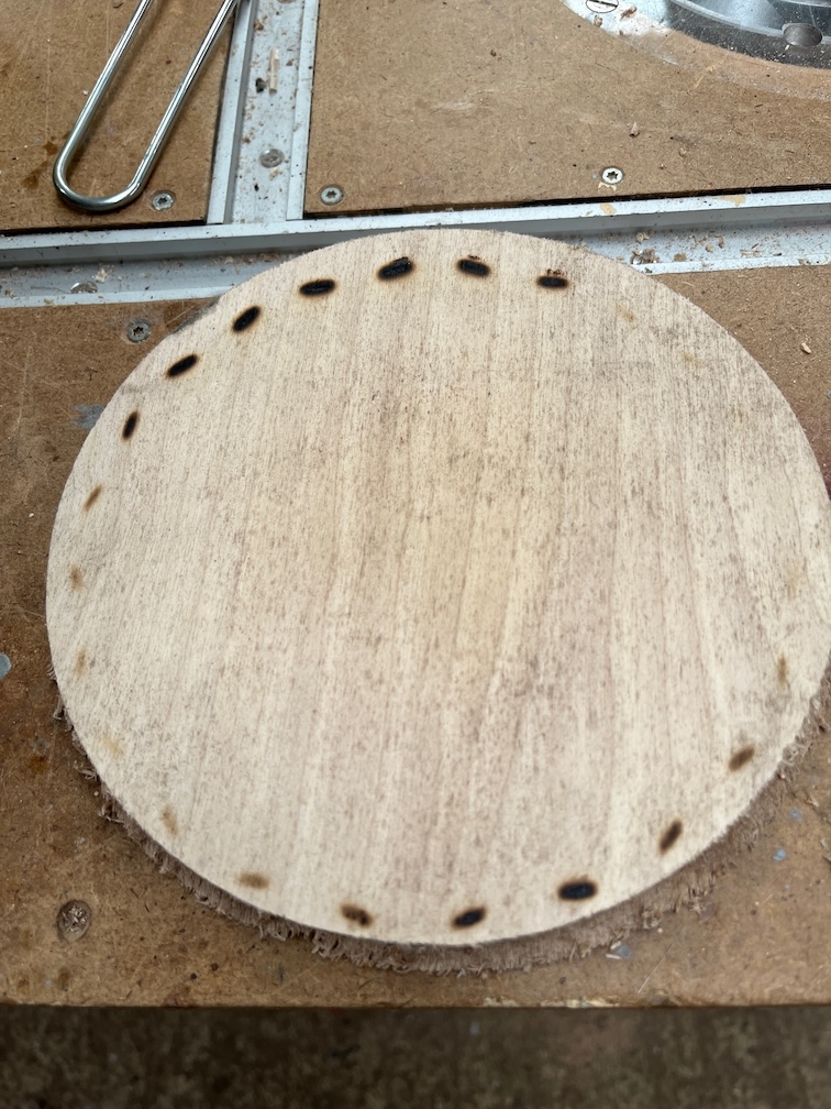
I boiled a kettle of water and then put the spreader on a piece of wood, just to see how bad the scorching was and as you can see, it’s not good. Several of the charred spots you can see here were smoking.
Still, with the spreader fairly well secured on the stove by the stepped pot stands, I don’t think this is going to be too much of a problem. If it becomes one in the future, I’ll try something else. A ceramic trivet, for example.
Time for a cup of tea.
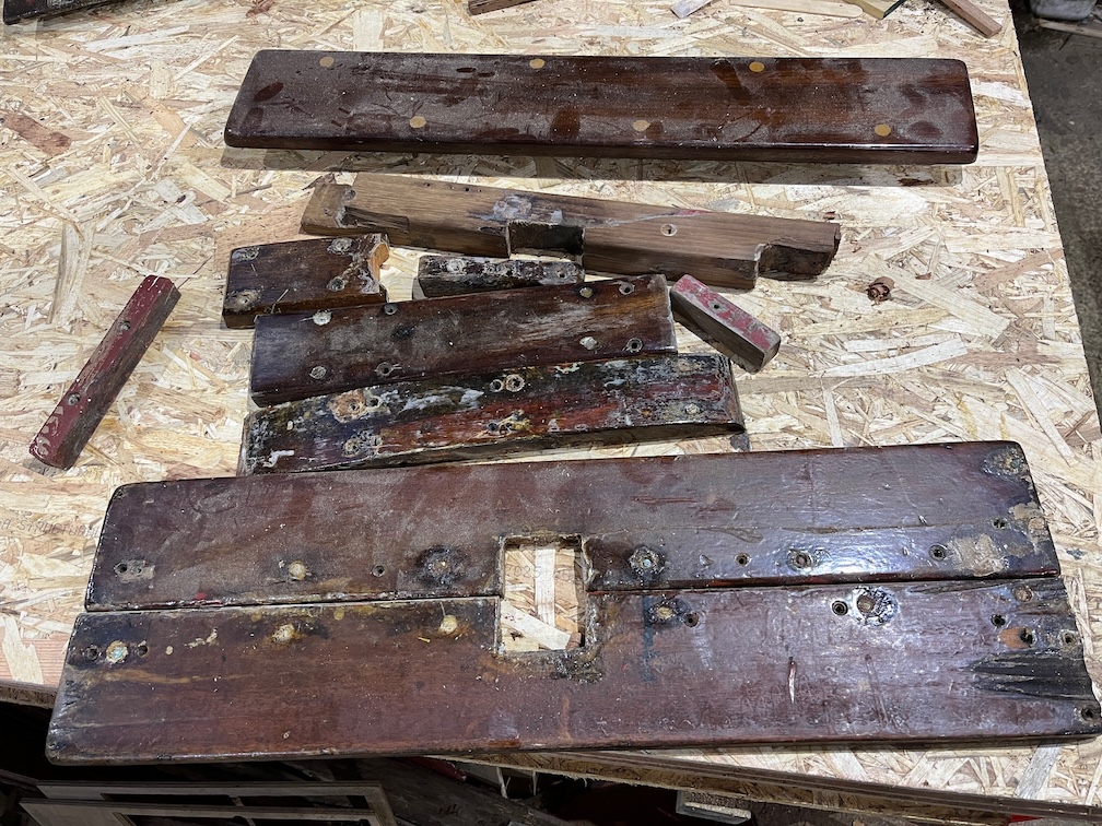
Finally, for today since the temperature is falling fast and affecting my fingers, again, I decided to tidy up a few of the pieces of Shoal Waters that I’ll be putting back in the places from which they were removed.
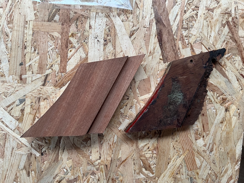
It is a simple task, just remove any loose varnish and sealant, check the edges for splinters and repair anything that needs it. This lot are fairly sound, mainly cosmetic damage.
These however needed additional work. Old screw holes were drilled out and plugged in the case of the grey piece, the other pieces need to be dried out, sealed with Clear Penetrating Epoxy Sealer and two of the pieces need to be glued back together.
If the wood dries out before I turn in for the night then I’ll apply the CPES, otherwise it will be a task for tomorrow.
The morning started the same way that it has done for the past fews days with varnish work. This time the bottom of the two boards and judging by the coverage, one is all they are going to get this time around.
I also put the heater on in Shoal Waters and put some stain on part of the new galley locker, the part at the back that will be visible.
This is the section of wood I mean. The white areas are where there has been glue on the wood and it doesn’t take the stain. Nevertheless, I shall bash on regardless and if it annoys anyone too much I’ll paint or replace it.
The resized locker lid has come out quite well. I washed the surface with White Spirit, dried it and gave it a coat of varnish. The far edge, which you can’t see, was bare wood and now has a coat of varnish. I’ll be putting varnish on that and the just stained wood in the coming days. It will not be as quick to do as the temperature is quite a lot colder out in the boat than inside the house. Maybe I’ll be able to get a single coat per day instead of two. The other locker lid was similarly washed and varnished but I’ll not do any more to that, one coat was sufficient.
The section of the locker lid that I cut off is really nice wood. I wonder where it came from. Charles was able to get wood from various places such as Mahogany from a man chopping up a billiard table (Sailing Just for Fun p25). Wood came from other places as well, a bank and the farm he managed before becoming a Civil Servant. These days this sort of thing is impossible, with the advent of eBay everything that looks even remotely useful is sold.
I need to see if I have any white paint so that I can paint the inside of the locker. The rest of the locker is very off-white paint due to age and I’d like to put the same type of paint on if possible, but if I do not have white then I do have some grey bilge and locker paint and I’ll just use that on the untreated wood. After all, it’s not going to be seen very often. After a quick trip down to the workshop I found that I did not have any white paint, so grey it is.
The peel ply was removed from the aft end of the skeg as the epoxy was sufficiently cured. The epoxy stayed in places despite the force trying to putt it off when removing the peel ply, a good indicator that it is well attached to the wood beneath. Another task crossed off the list.
The epoxy on the underside of the new aft bock top piece was carefully sanded back to the wood.
But the epoxy on the top surface was left as is since once the top piece has been glued in place it will be sanded to blend into the old block.
Time for a cup of tea.
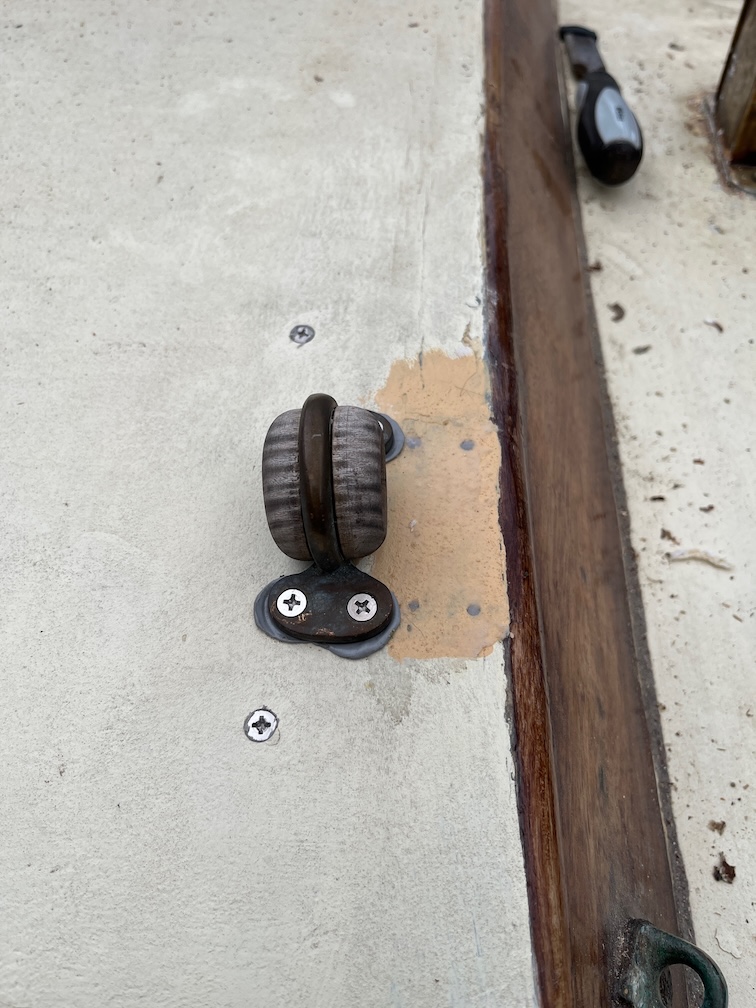
The next task is to get the bullseyes done. Nothing difficult about this, just potentially messy.
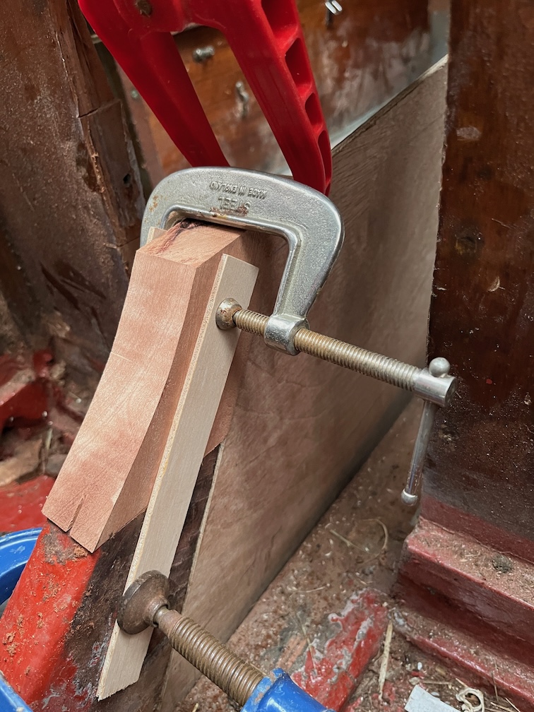
The backing pads were put into the correct place and wedged there using two battens clamped together as shown. Not elegant, but it works. You do really need three hands to do it, one to hold the pad in place, one to hold the battens and a third to fit the clamp and tighten it up. You can get a single-handed version of this, I’ve watched other boatbuilders use them.
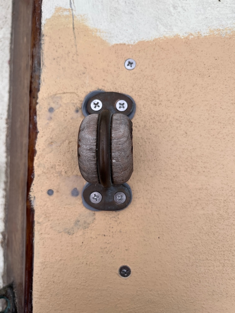
Anyway, the top and front surface is covered with sealant and the pad is screwed in place from the outside. Once that is done the bullseye can be fitted.
The four screw holes through the coachroof are clearance holes and chamfered so that the butyl tape has somewhere to go. You can see the tape on the screws in the bullseye.
The screws are tightened up a litte at a time until they are tight and you can see the tape squeezing out. I’ll run a sharp knife round the fitting later and remove the excess.
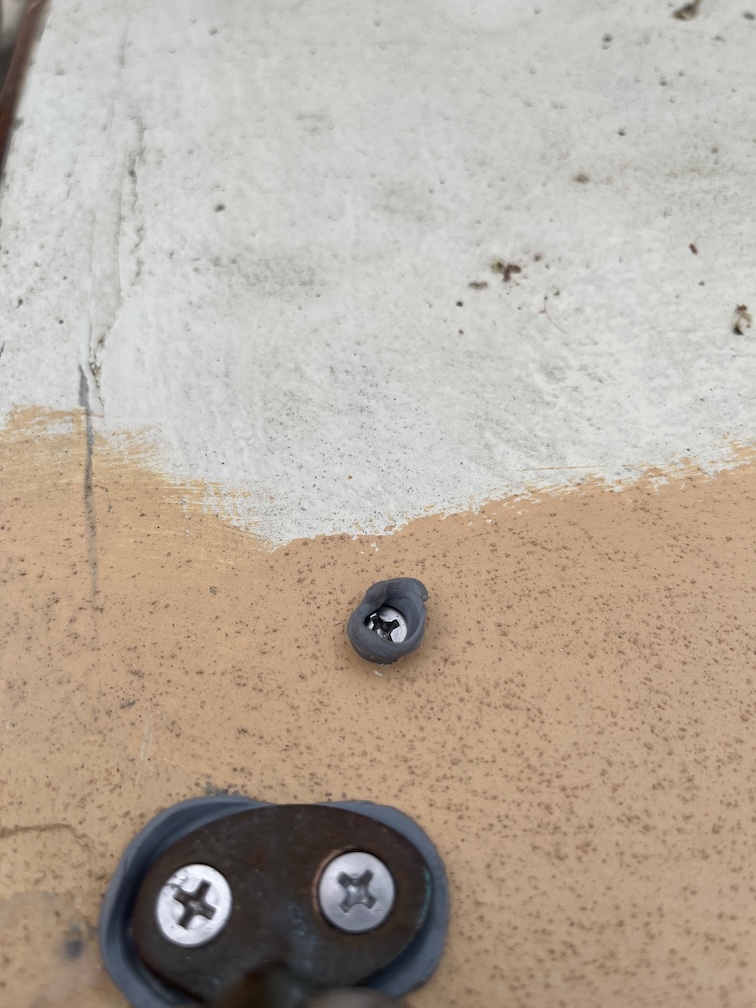
The screws holding the pad initially were backed off a little, butyl tape wrapped around the thread and then screwed back in again. Here the squeeze out is obvious.
The excess is easily remove just by pulling it off.
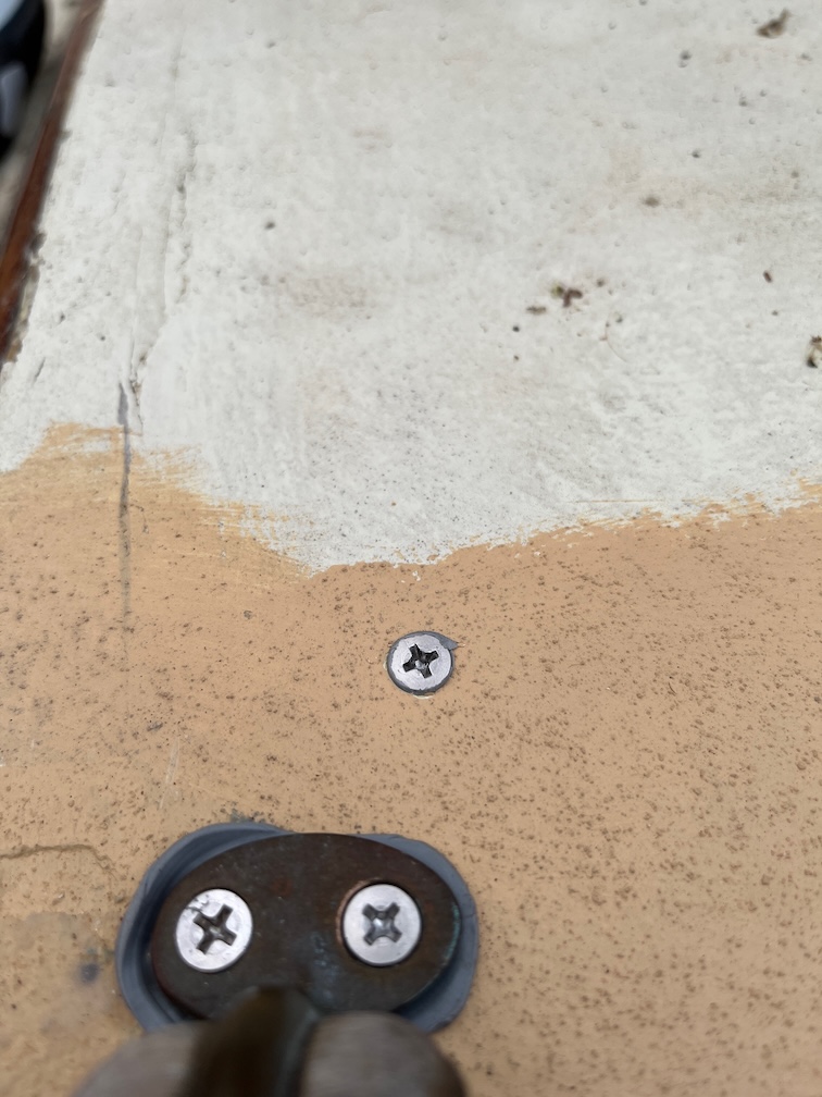
The other bullseye was similarly treated and yet another task can be ticked off the list.
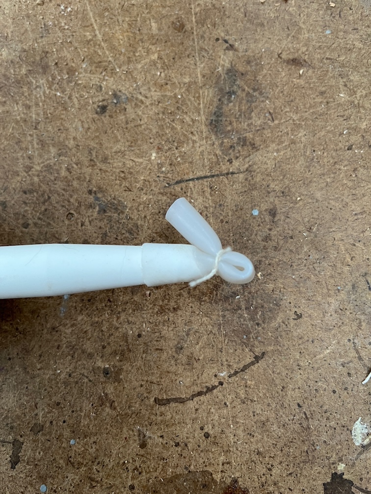
I have a shed load of 6mm silicone rubber tubing in the workshop left over from when I added a water-cooled spindle to the CNC Router and I found a use for some of it.
I cut off a short length, slipped it over the end of the sealant nozzle, bent the tube over and tied it tight. Useful that.
Time for a cup of tea.
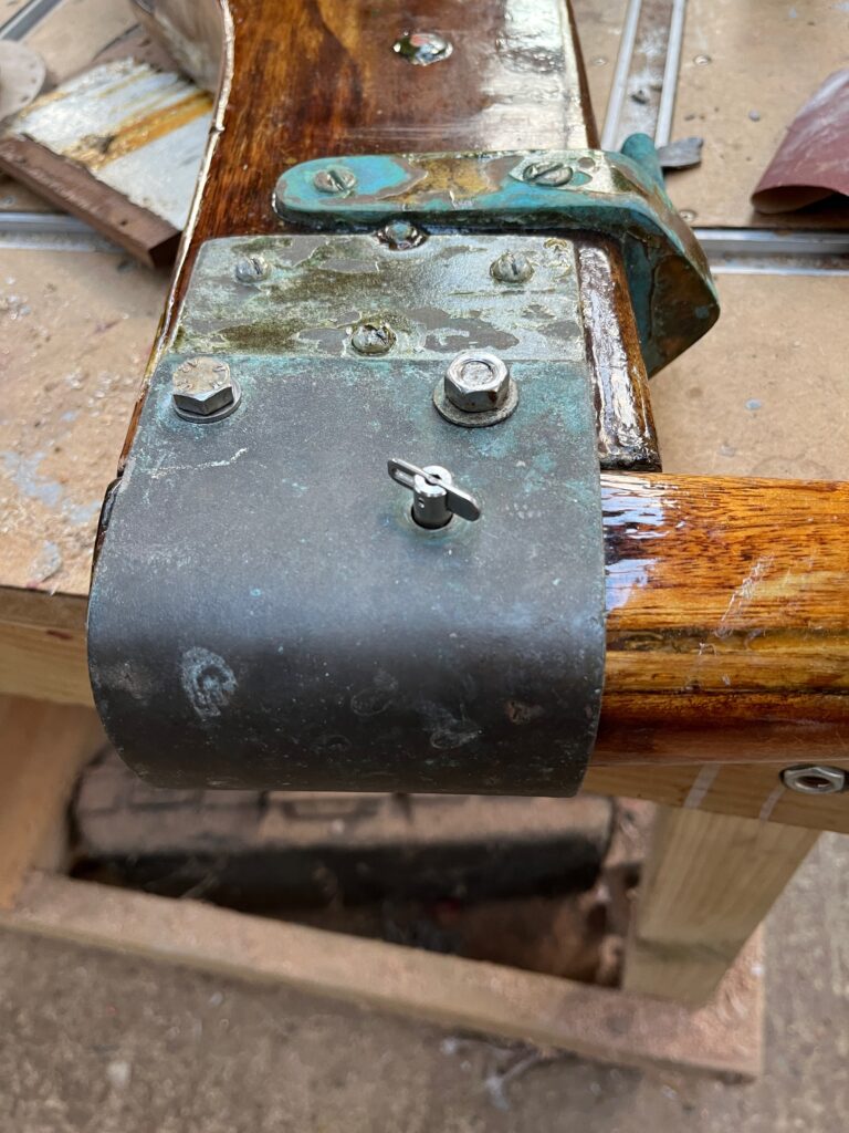
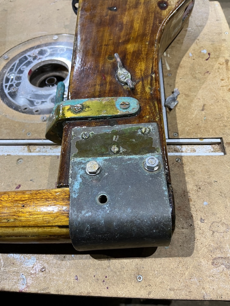
The next task is the tiller and rudder. When we collected Shoal Waters from the Goldhanger Sailing Club, the tiller took some persuading to come off. There was a brass bolt through the top of the rudder stock and through the tiller and it came out easily. The bolt was 1/4″ and the hole a bit bigger than that but I had to resort to hammering the tiller out with a mallet. Well, a hammer onto a piece of wood that was on the back of the tiller, but it is easier to say mallet.
I decided at that point that one of the tasks would be to fix this such that removing the bolt would allow the tiller to count out freely. Now is that time to make that happen.
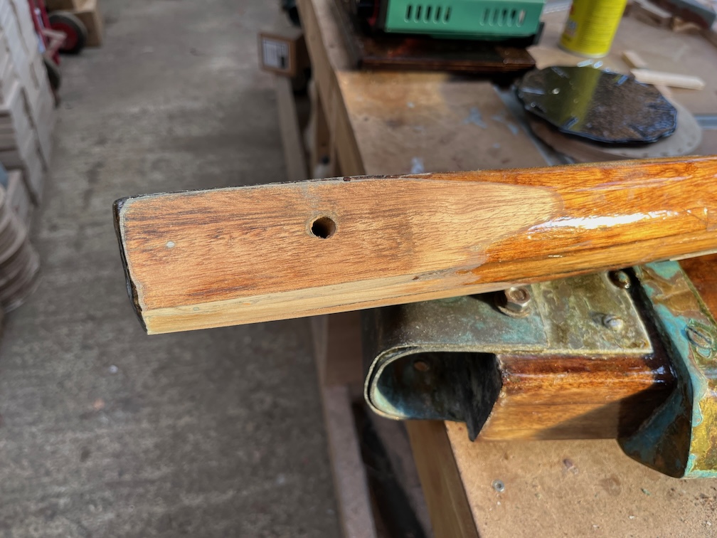
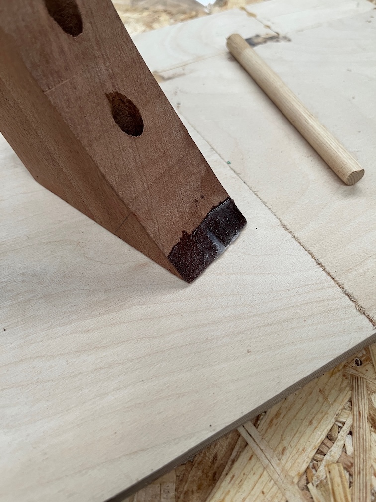
This is the slightly modified rudder stock in that the two holes holding the bolts you can see and the hole through the tiller were drilled out to 8.5 mm. This allowed the two bolts holding the brass (bronze?) tiller holder to the top of the rudder stock to fit properly and also allows the use of an M8 and 80mm long drop nose pin. Or will when it arrives.
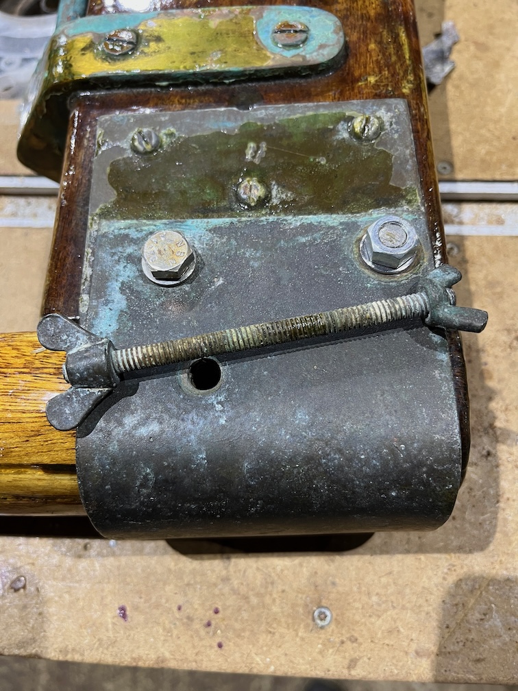
This is the original through bolt that prevents the tiller from slipping out. There’s nothing wrong with it except that getting it out in a hurry isn’t really possibly whereas using a drop nose pin is quick and easy to remove.
I put an M8 long bolt through the hole to check the clearance.
So, another task done. When the pin arrives I shall tie it to one of the bolts so that it can’t get dropped overboard by accident.
First task was to apply yet another coat of varnish to the top surfaces of the galley stove boards, this is the fourth and last coat for the tops. Once this has dried a little I’ll put them on the Rayburn to warm up and harden the varnish.
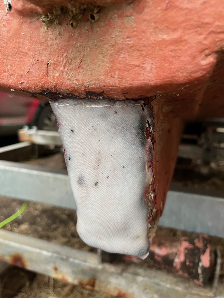
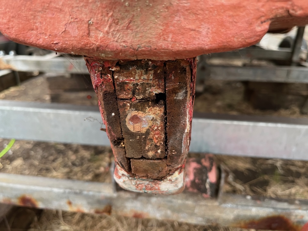
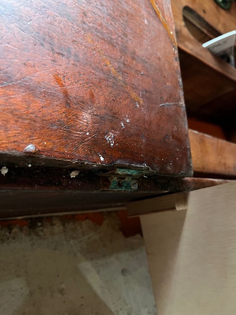
I decided yesterday evening that I really needed to do something about the bottom half of the aft block.
As you can see from the photo, parts of the front are damaged due, I have to say, to my slightly too aggressive work with a chisel when trying to get the old case sides out. There were, I decided, two practical ways to go about this. Firstly was to just cut the entire front off and replace it and the second was to fill in the damaged sections with thickened epoxy.
I decided to go with the second option as I have to make up some epoxy to fill in the accidental saw cut in the back of the new piece.
First thing, the heater was turned on and the warm air direct on to the aft block from inside the cabin. However, later on I took a look at the damaged section and it is a lot less severe than it looks in the photo, so I decided to leave it. The front part will be coated in neat epoxy before the sides are fitted and I’ll just make sure that plenty of epoxy is brushed into the damaged area.
The next task while I waited for the CPES applied yesterday to cure was to finish the bullseye backing pads. This could have been a bit messy since the procedure was to mix up a fair bit of thickened epoxy, spread it on to the top and front edge of each pad, cover the epoxy with clingfilm and then each pad was pressed against the coachroof where they will be installed.
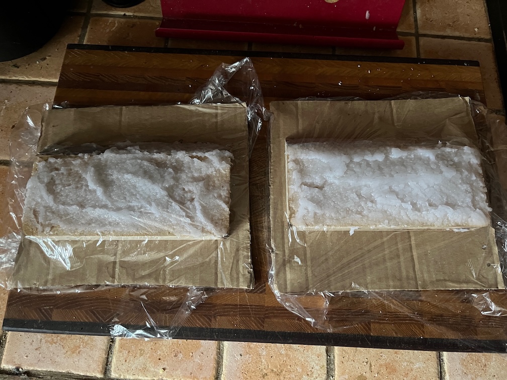
Here we go, lots of thickened epoxy on the backing pads, resting on cardboard (to catch any drops) and covered with clingfilm.
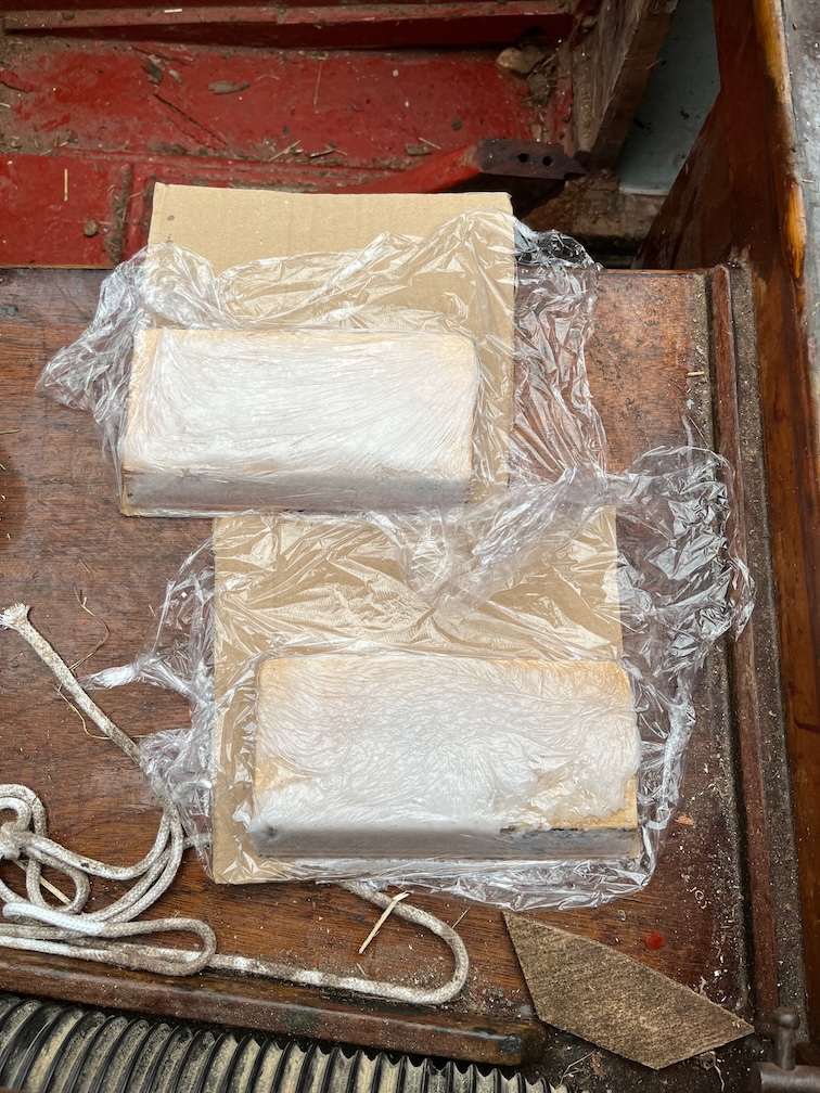
And here, a short time later, the same backing pads having been pressed against the coachroof. There are still gaps in the epoxy, but it is close enough and I can put more in these gaps and smooth it over.
I made a lot of epoxy, this is one of the reasons for that…
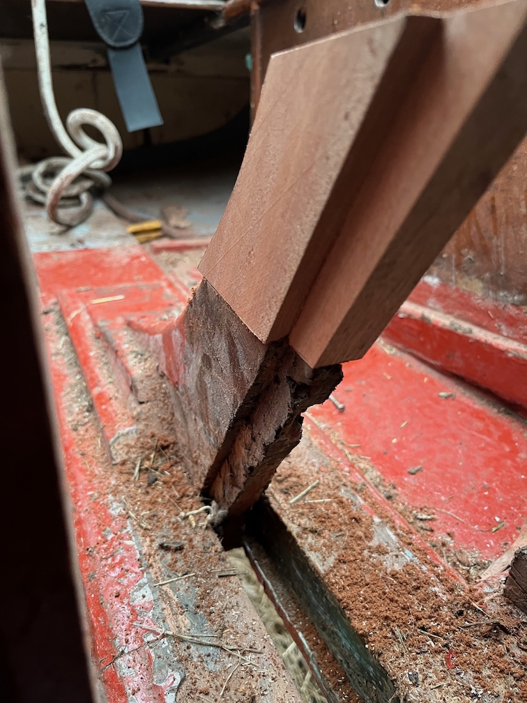
…and this is the other. The aft end of the skeg needs some repair. I think that the original is three long pieces of wood stacked on on top of the other, with two side pieces to hold it all together.
Like this. The red green and yellow pieces are the ones stacked on top of each other. The white pieces are the two side pieces holding everything together. That is the original skeg. at least I think so.
At a later time another piece has been added to the bottom of the skeg and various dings and scratches filled with epoxy. The back part of this has been partially knocked off so I took a chisel to the whole thing and removed as much of the loose parts as possible, then sanded it with 80 grit sandpapar.
This was slathered with the thickened epoxy and a layer of peel ply put over the top. This will be covered in antifoul paint before being launched and if I leave the amine blush on the epoxy, the paint will come off. Besides which, the peel ply allows me to smooth the epoxy down with my hand (wearing nitrile gloves) and that all by itself is worth doing.
You can see the addition to the bottom of the skeg more clearly from the side.
I also filled in the old screw holes where the bullseyes were.
I will need to go over both these areas with a sander to remove the excess epoxy, but I will have to do that in order to apply the new paint.
One of the holes did develop a short tail as I pressed too much epoxy into the holes from the outside.
But that was easily removed and I used the tail to fill in a nearby hole in the upstand.
With the temperature forecast for the weekend getting down to near zero and possibly with snow, I want to get any outside epoxy work done today so that it stands a good chance of curing before the temperature drops.
Time for a cup of tea.
The next task was to resize the locker lid so that is fits since about a third of the original length has now been allocated to the galley stove.
This was a pain to do as I had to reuse the brass hinges but with stainless screws and getting them screwed in was awkward. Still, it is done now.
The result isn’t too bad. I gave the lid a light sanding and will add some coats of varnish in situ. I don’t want to remove and replace it again. The cut edge need to be varnished from scratch but the rest of the top can just have a coat or two.
I also took the time to add screws to the various battens in the galley locaker. These have been glued using cyanoacrylate glue which is very good but it is brittle, so I added the screws, just in case.
The first small task on the list today was applying a second coat of varnish to the top side of the galley stove boards.
The boards are starting to look a lot more shiny than for the first coat as that soaked into the wood. This one did not, or not so much, since the first coats sealed most of the wood grain.
The glue up of the wood for the new top section of the aft block seems to have gone well, so it was out to the workshop to remove the rough surfaces.
The planer puts a lot of pressure and stress on the wood as it is cutting off wood from the surface and if a joint is not particularly good, then this usually results in the join splitting apart. In this case it didn’t so all is well there. I planed the wood down to it’s final thickness and now it is ready to go.
To prevent more cutting that necessary I aligned the straight front edge of the paper template with the edge of the workpiece.
The next task is to cut the rebates as doing this now whilst the block is still large and rectangular will prevent mishaps trying to do this later on when it is not.
Four passes on the table saw and that is done.
Mind you, I messed this up and made a cut in the wrong place for the first cut. Still, this will be minimal once the piece has been shaped and any errant slot remaining will be filled with thickened epoxy.
Time for a cup of tea.
First the two easy cuts made on the mitre saw.
Then a straight cut at the back to get closer to the line made on the bandsaw (carefully).
Then the excess was sanded away using an oscillating sander. So far, so good.
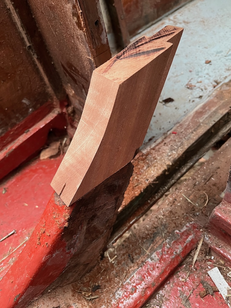
Not too bad for a first approximation. The front and sides are pretty much an exact fit, but the back has missed, fortunately on the plus side, not the minus.
Here’s an inside view and the mismatch at the back is slightly more clear in this photo.
And this from the other side.
Time for a cup of tea.
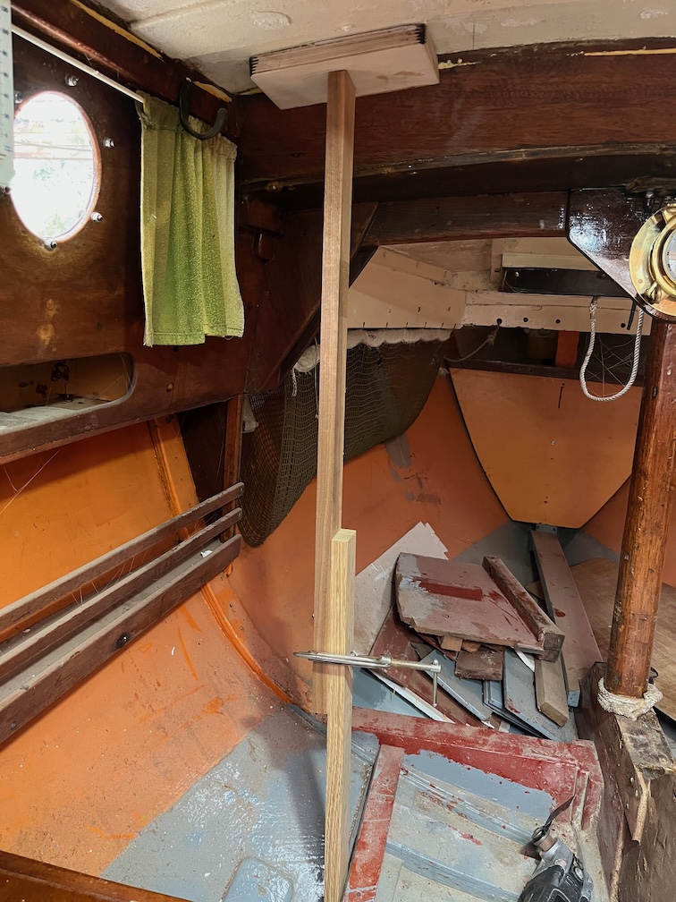
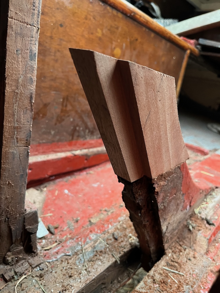
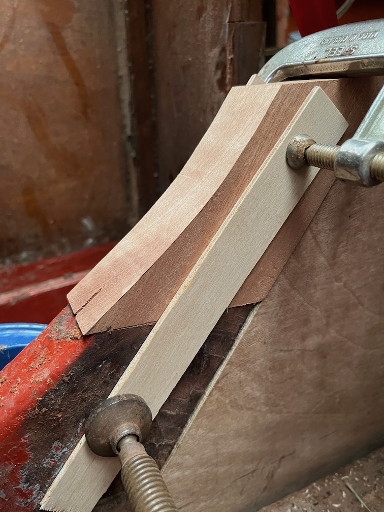
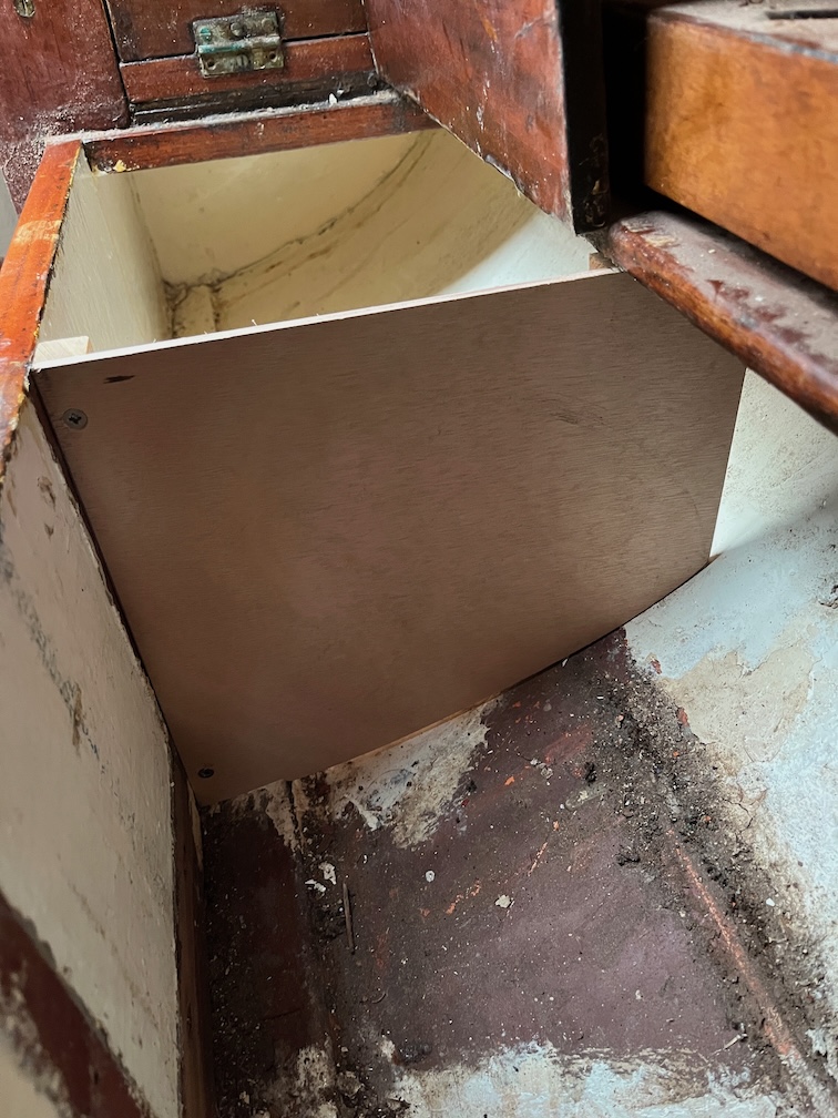
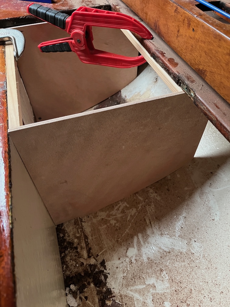
The next task is to put in the case side template and see how that fits with the new top.
The template was put into the keel, clamped to the top and two thin battens clamped either side of the aft block spanning the old and the new as you can see above. These were to keep the new piece in position and upright as much as possible.
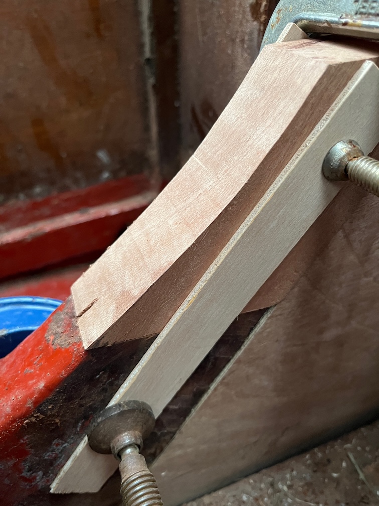
Looking at the new piece now you can see that the bottom of the curve on the new section isn’t that far off.
So, I carefully sanded a bit more off until it was a pretty good match.
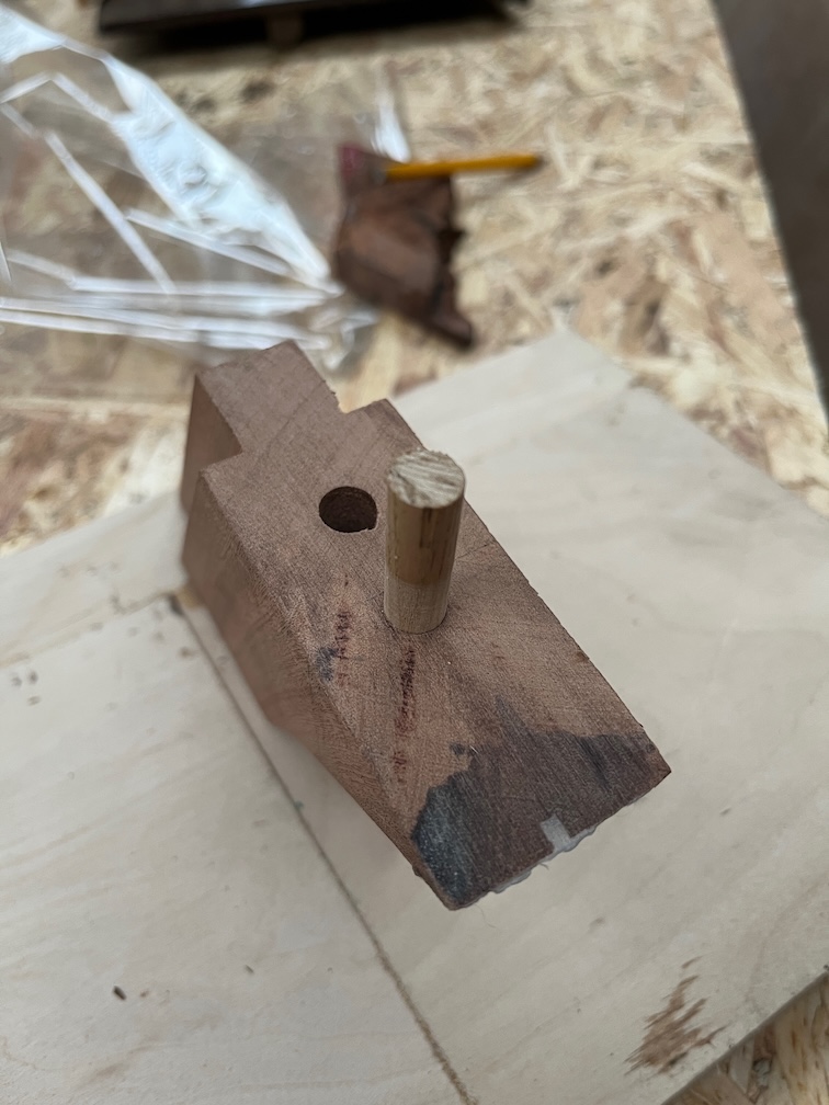
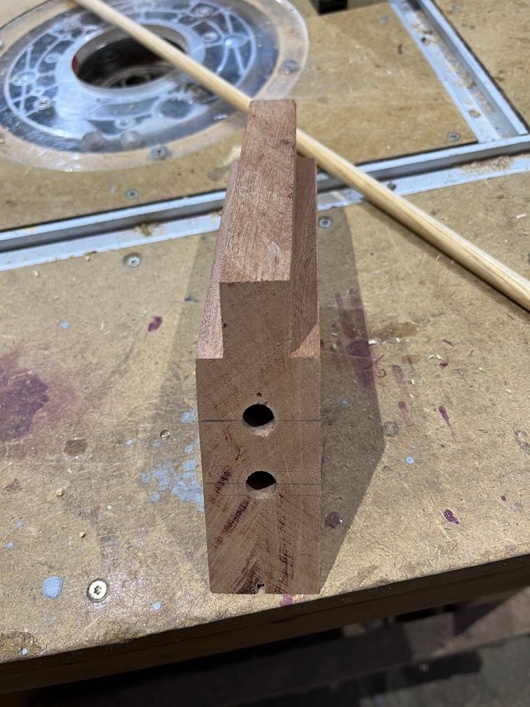
Using a self-centering dowel drilling jig I drilled two 10 mm holes through the new top, both being perpendicular to the bottom.
I chose to drill them completely through the block rather than attempt to drill matching holes in the old section by guesswork. This way I can clamp the top piece in place and drill down through the holes and get a perfect fit.
The block clamped in place…
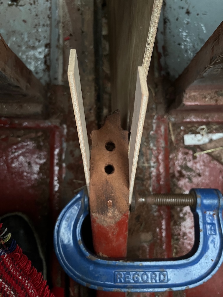
…and the resulting holes in the bottom section.
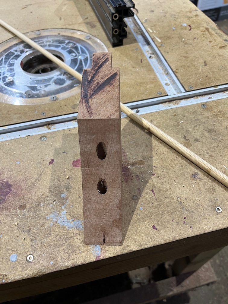
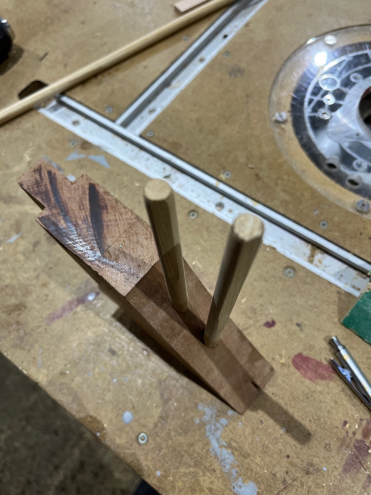
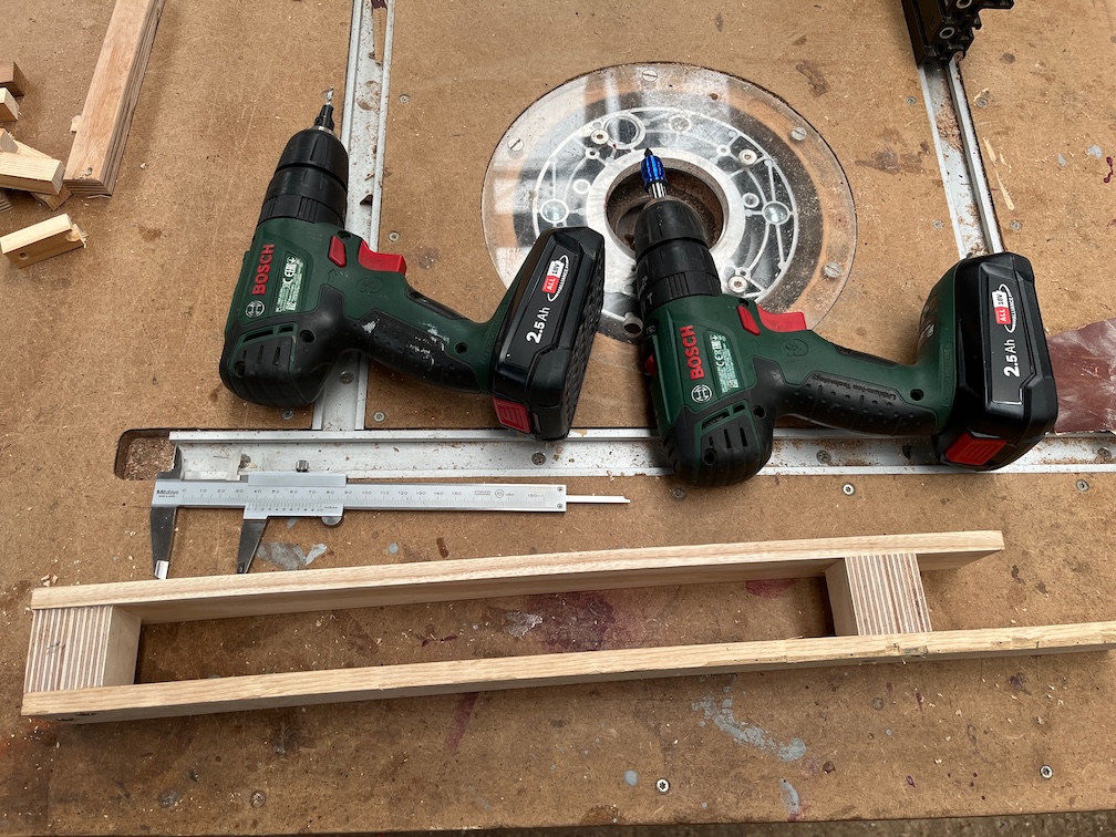
I used two pieces of an medieval style arrow shaft, made from Ash, which was 10 mm in diameter and sanded it down a little to make it a loose fit. I put each piece into a cordless drill, wrapped coarse sandpaper around the shaft and spun the shaft until the desired fit was obtained.
Finally for this part I sanded a flat section on each shaft. Without this the dowels will not seat properly as the pressure from the air and glue being forced into the hole pushes the dowel out again. This is the reason that the dowels you buy from a hardware store are not round but ridged all round.
The holes in the bottom section were filled with Clear Penetrating Epoxy Sealer and I was gratified to note that the CPES did not soak in much, indicating that the wood through which the holes were bored were not porous. I did coat the top of the wood and that did soak in but that is endgrain and I would have been perturbed if it had not on any but the very densest woods, of which this is not. I also put CPES on a number of other areas in the boat that have been waiting until I had enough to make it worth mixing up a batch.
That concluded the outside work for the day, inside I put the third coat of varnish on the galley stove boards.
Not a bad day’s work. All small things but on the critical path. While I wait for the CPES to dry, three or four days in this temperature, I’ll finish off the case sides which need to be trimmed and a bead of sealant put all around the outside corners where water could collect.
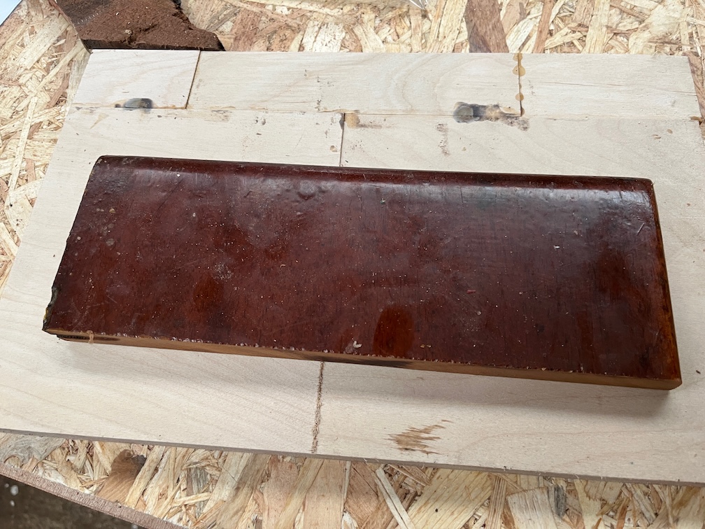
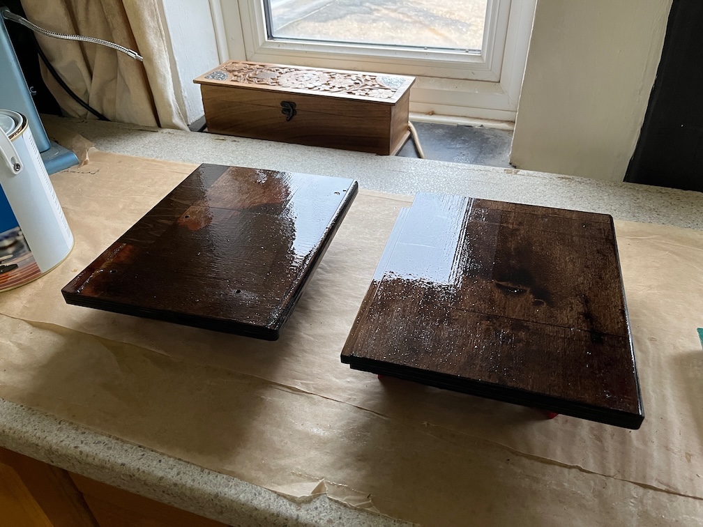
Today, being a work day, means that I carried out small tasks that could be done during a teak break or before breakfast. First up was the galley stove locker lid which is basically a copy of the board upon which that stove is mounted but without the stove.
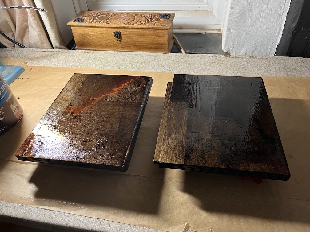
Very easy to make there’s no glueing or awkward bits and the result here has a coat of stain on both sides. I’m using some trapezoidal standoffs to keep of off the work surface.
Whereas the stove base board, which has holes, is hanging from a string in the rafters and now has two coats of stain. Once both have two coats of stain and are dry they will be varnished with a few coats before being ticked off the to do list.
Time for a cup of tea.
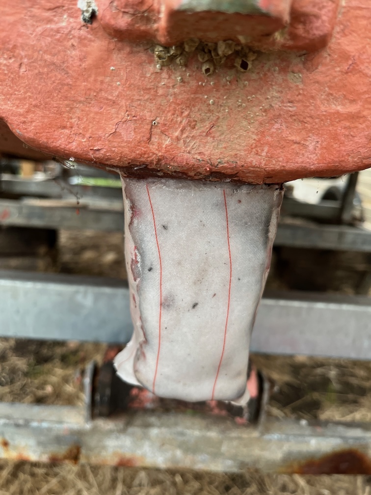
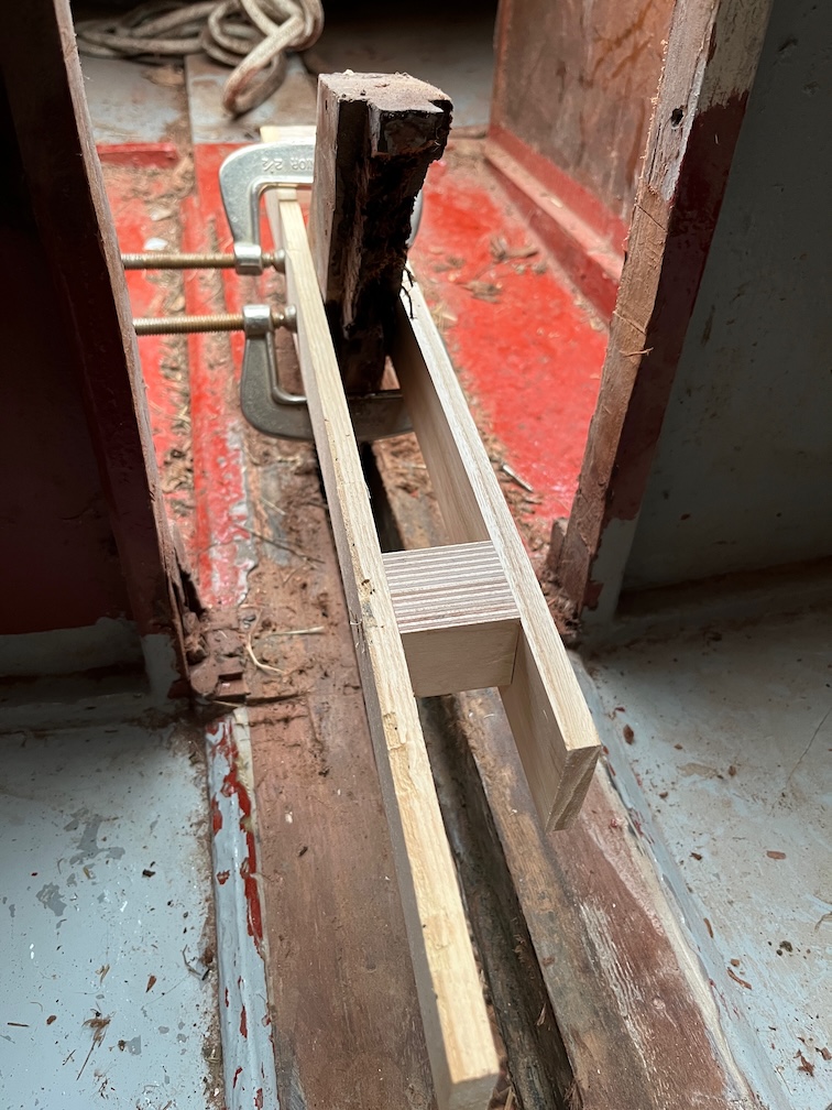
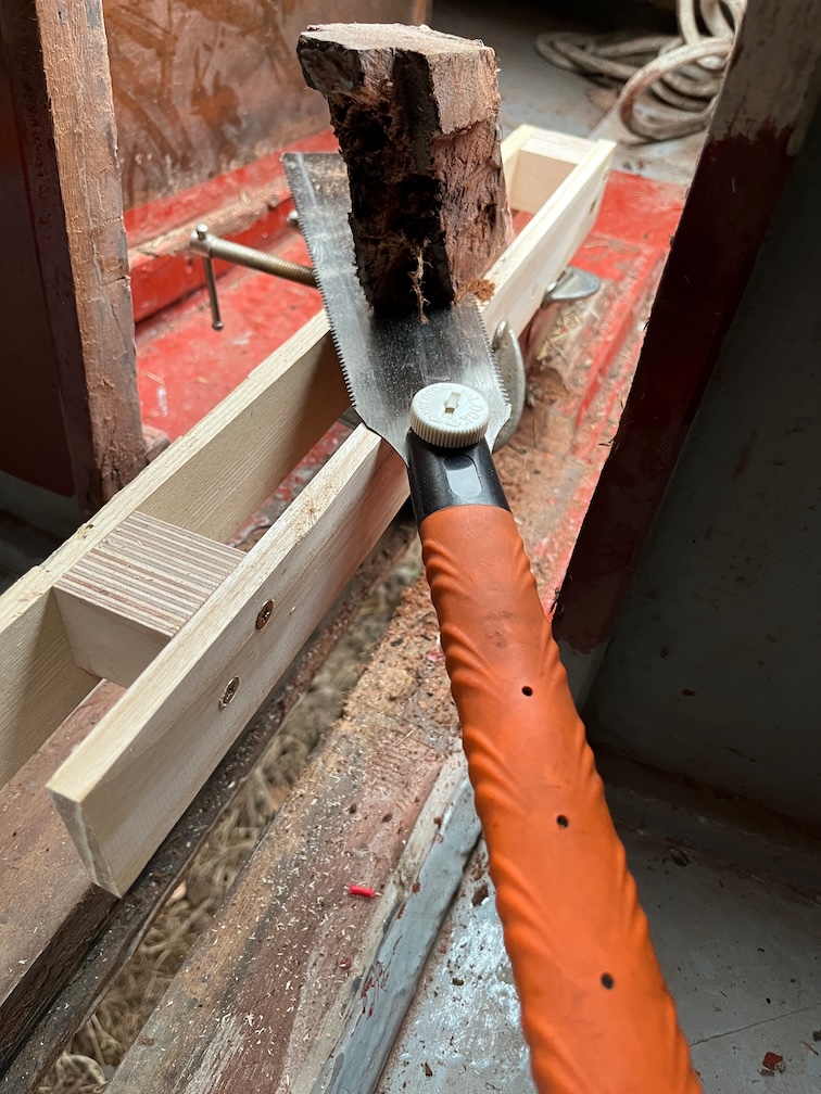
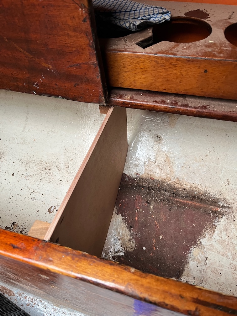
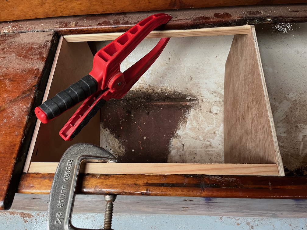
The next task on the list was to make a saw jig for the aft case bock so that the rotten/soft section could be sawn off by hand with as smooth and flat a cut as possible. The problem is that the space was sufficiently restricted so as to prevent the use of either a circular saw or a jigsaw, or at least the ones I own, and also all my hand saws with the exception of the pull saw. This blade is very flexible and to get an accurate, flat cut in such a tight space required a jig.
Essentially, I clamped two identical battens either side of the block and fitted two spacer blocks at either end. These held the two battens apart the same width as the width of the block. I made sure that the battens were parallel, straight and screwed them to the blocks such that they formed a rigid structure. This jig was placed over the block such that the upper edges of the battens was at the correct place for the cut and the jig clamped securely in place.
Now the pull saw had two guides, one on either side of the block and I could carefully cut off the top.
I had to use the saw from the inside as the cockpit was too narrow for the saw.
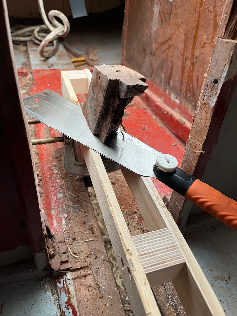
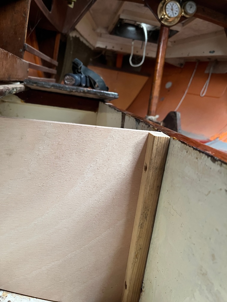
But here you can see the saw in action and also the function of the saw jig which, I have to say, worked better than I expected.
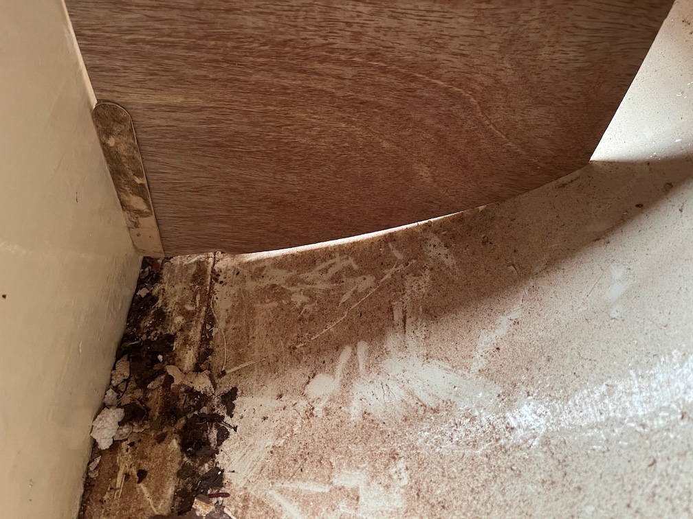
A slightly different angle on the cut.
This shows just how well the jig worked, the cut is clean and flat.
Of course, it took longer to carry out than it did to describe it !
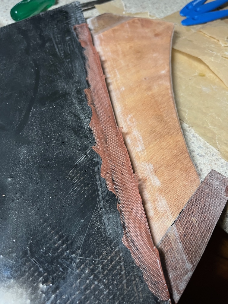
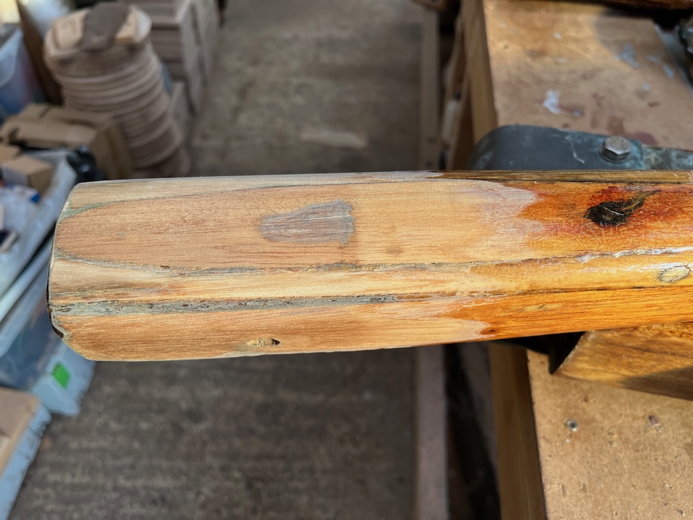
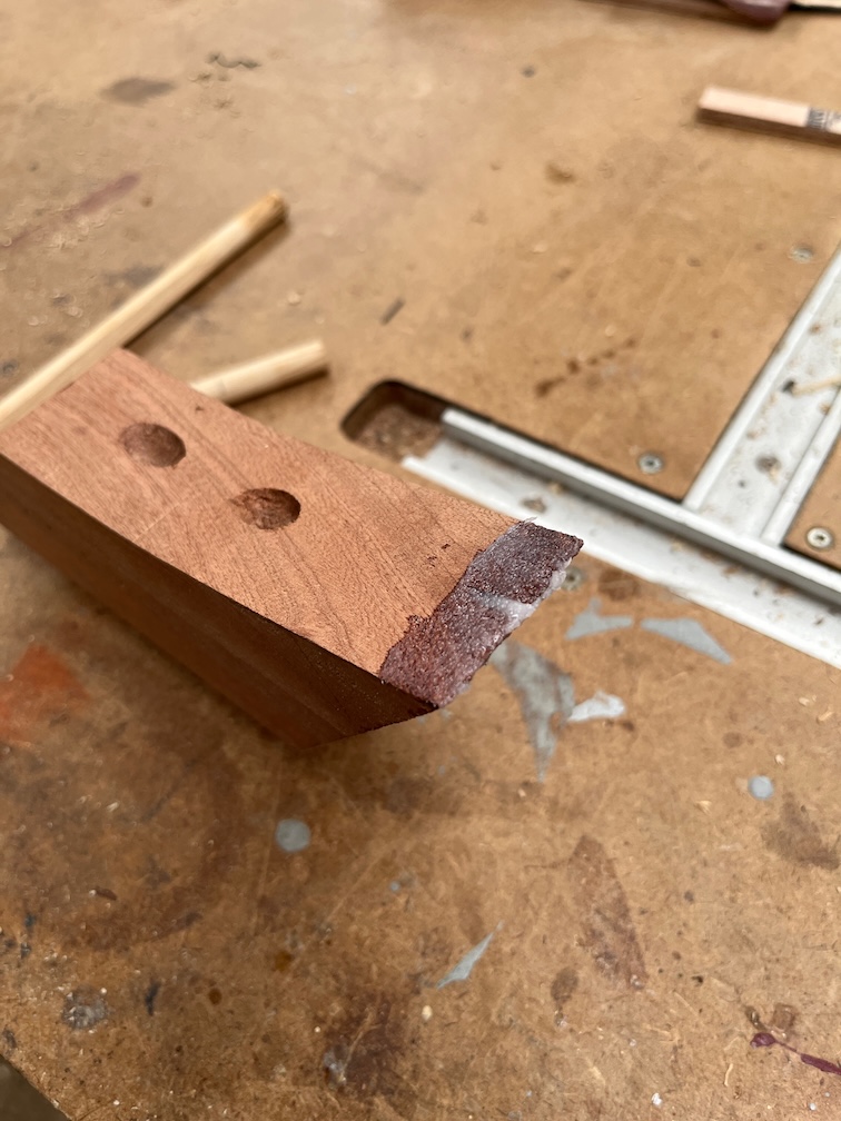
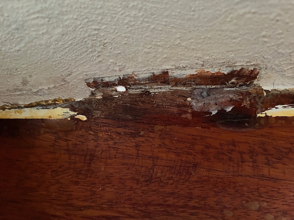
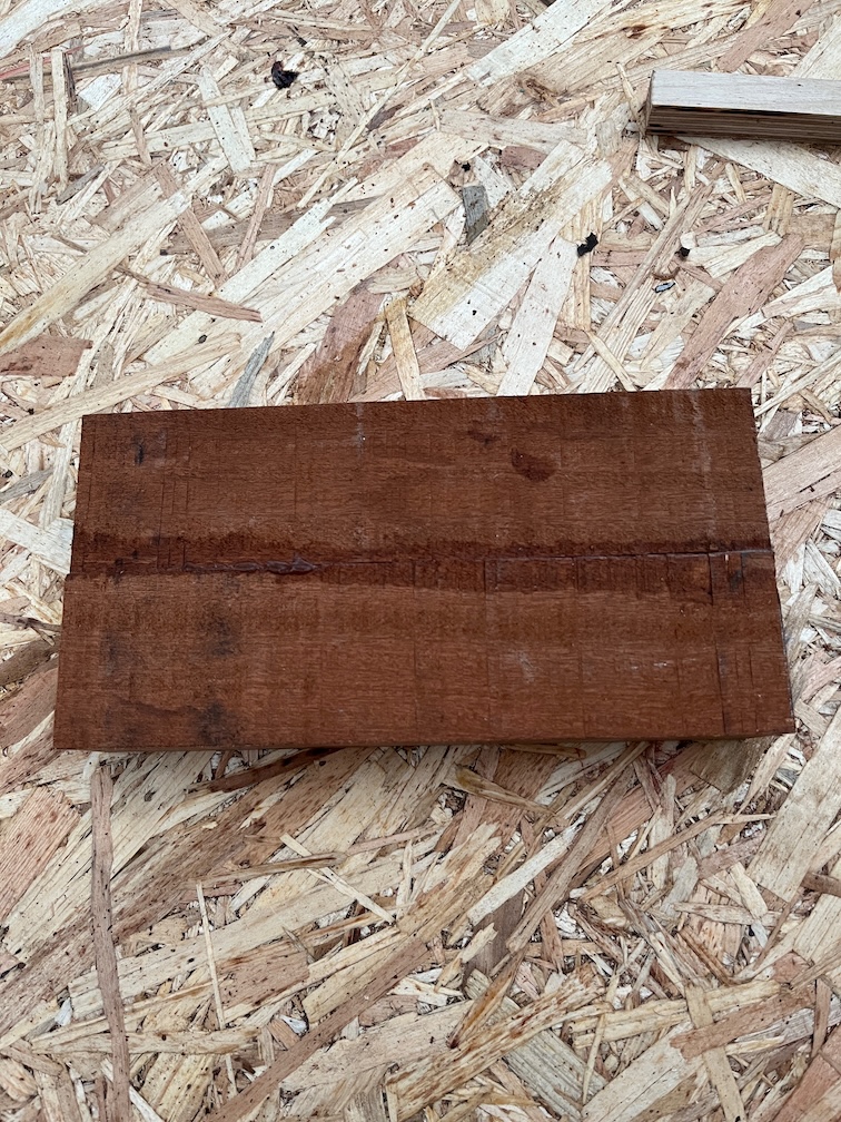
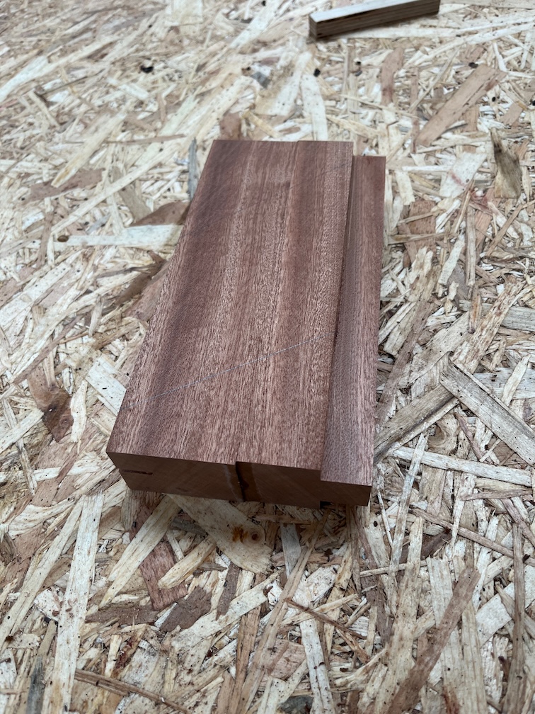
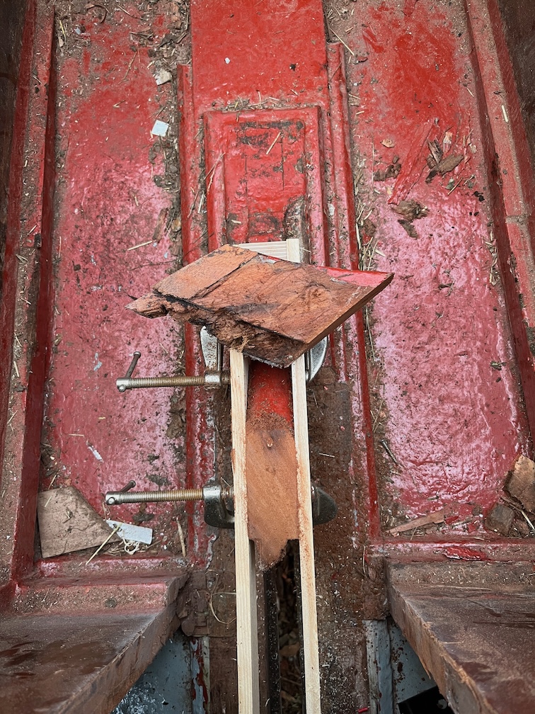
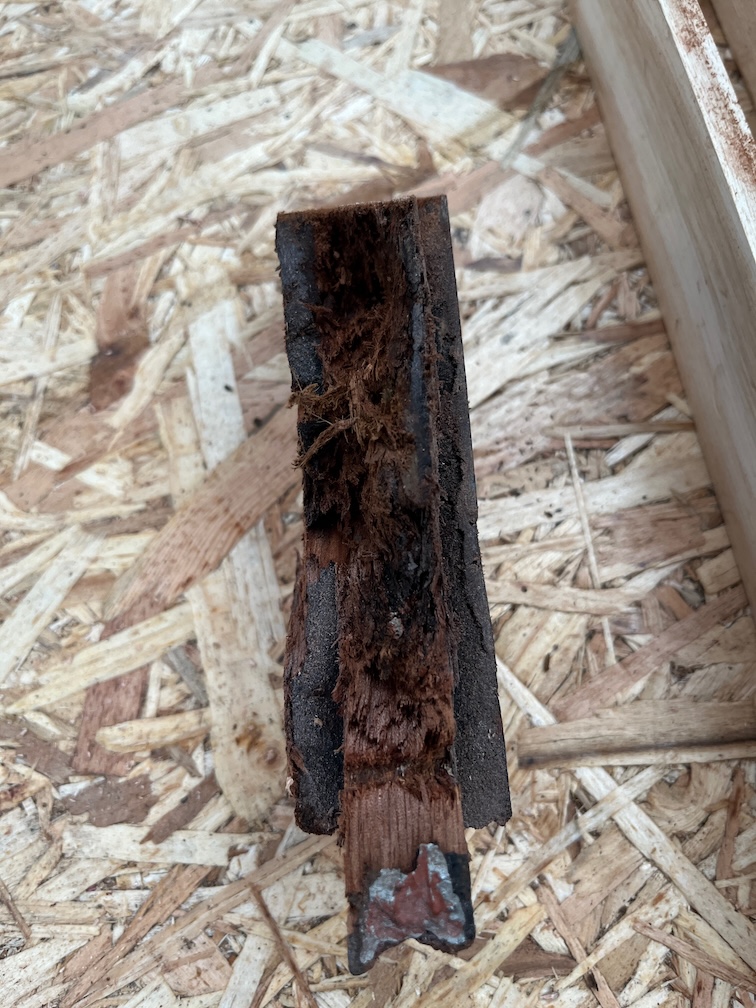
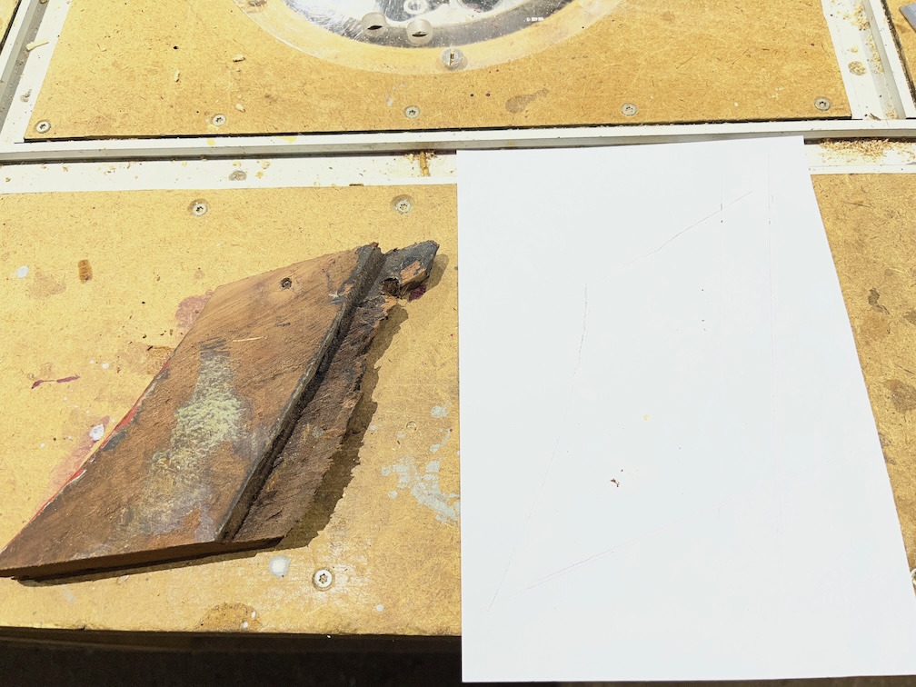
Back in the workshop I could take a look at the offcut. Like this it is not that informative.
This shows more clearly the problem.
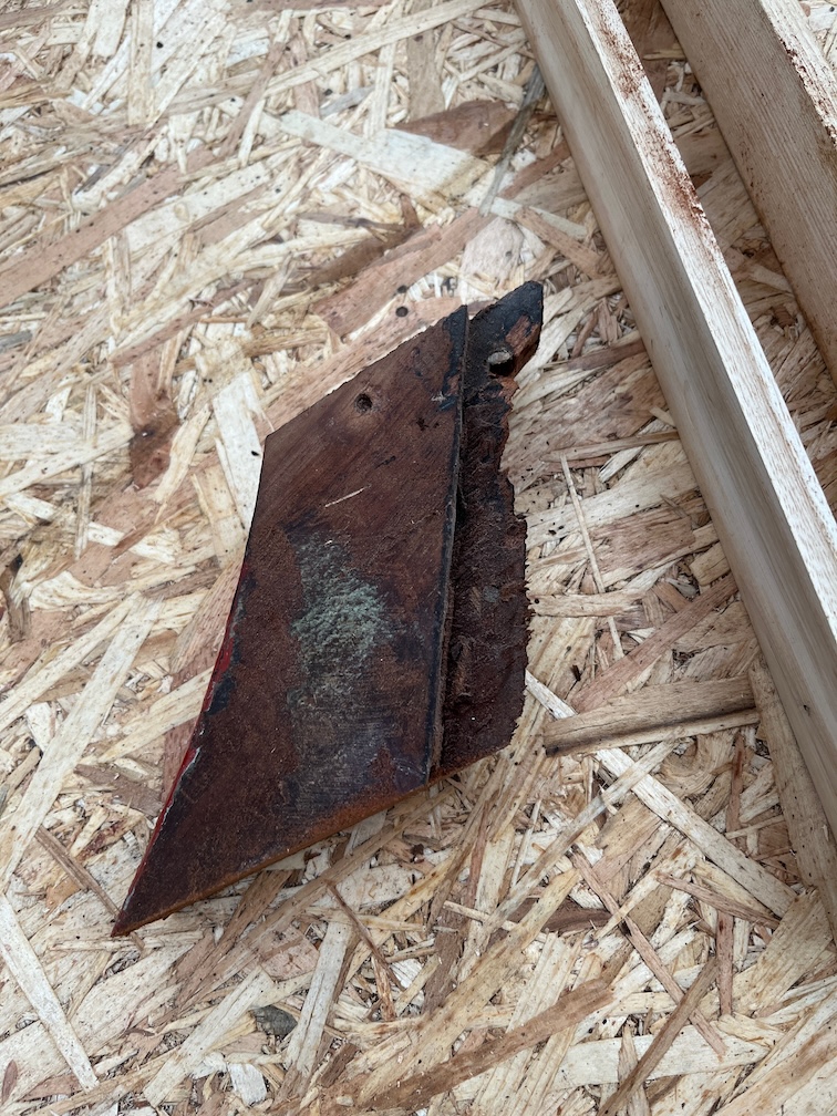
I had to cut the piece in half lengthways because I need the shape to make a new piece and with rounded edges on the outside, this would have been difficult. However, cutting it in half did give me some more insight into the issue.
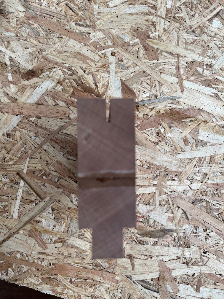
The soft, and possibly rotten, part doesn’t really extend into the body of the offcut except in one place. There are two holes that have been filled with some kind of filler, one a screw hole and the other a larger void for something.
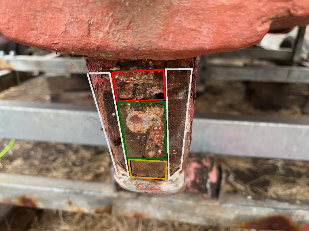
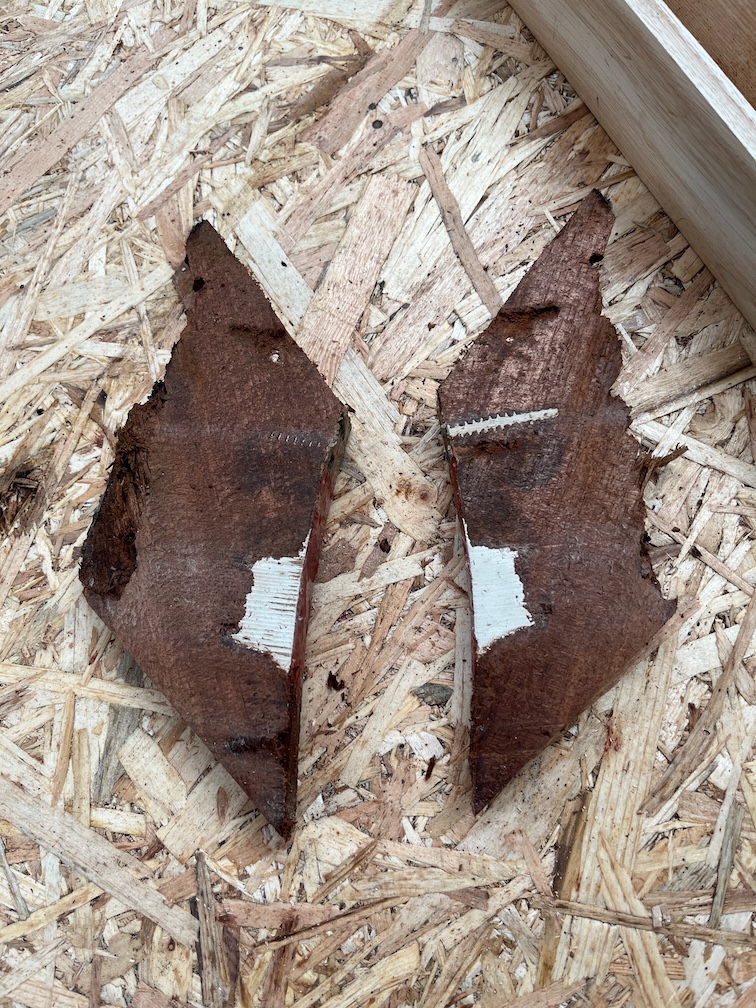
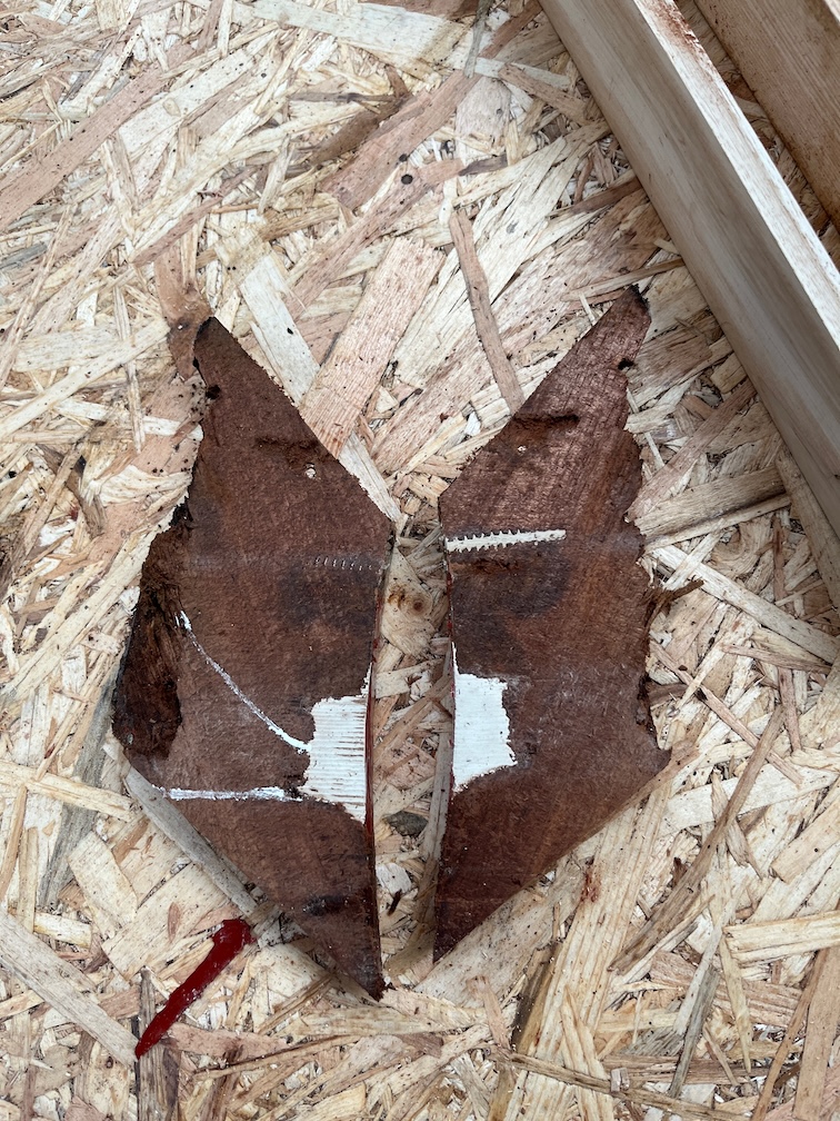
Here’s the interesting thing. Poking around the soft area I found that the really obvious soft wood was joined to the larger of the filled in sections. I’ve marked that soft section in white. The inner surfaces of the centerplate case were coated with a waterproof glue, including the fore and aft blocks, so unless the glue layer was damaged then the softness was unlikely to start from the inside, especially since that part of the block is above the waterline most of the time.
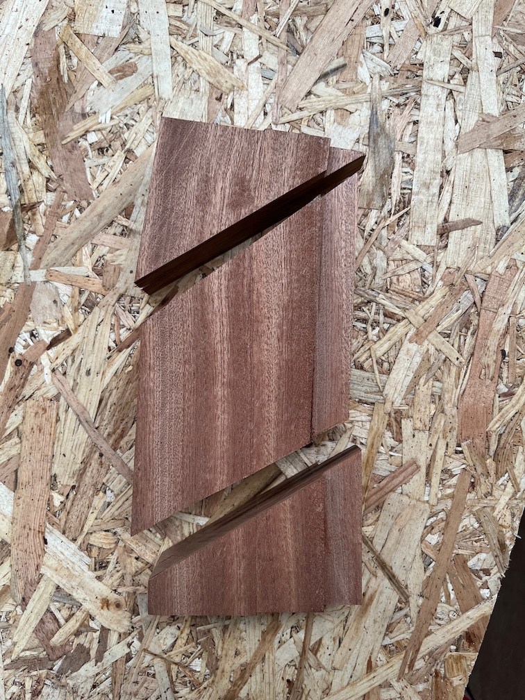
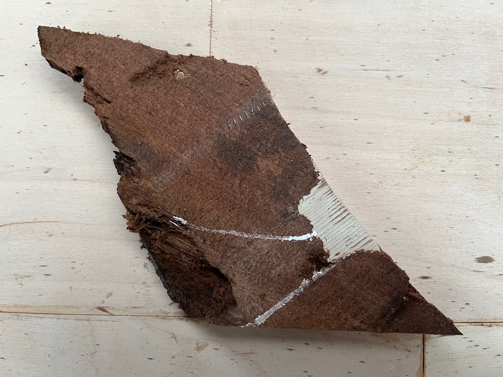
If I rotate the piece so that it is shown as it would be in the boat, you can see that the large filled void slopes downwards and the soft wood goes to the bottom part. You can see where I picked out some of the soft wood with my fingernails. So, one possibility is that this void was left open for some time and both fresh and salt water was allowed to pool in the bottom eventually causing the wood to become soft.
In the above photo you can also see a lighter area from the pointy end of the screw hole diagonally down to the edge of the block. This is also a bit soft and the same thing may have happened here.
I have highlighted the bit I’m referring to in green.
Nevertheless, my cut was nearly perfect, just below the extent of the soft wood. Making a new piece to replace this should be fairly easy and the next tasks in the never ending saga of the centerplate repair !
Well, it seems like it.
Time for a cup of tea.
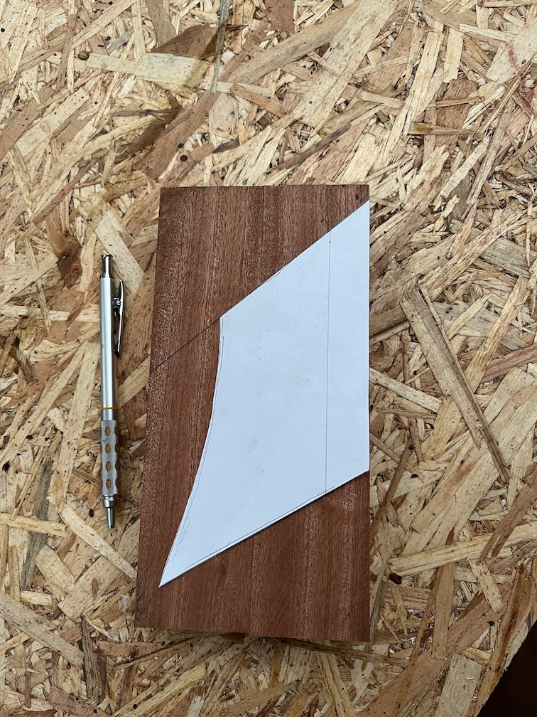
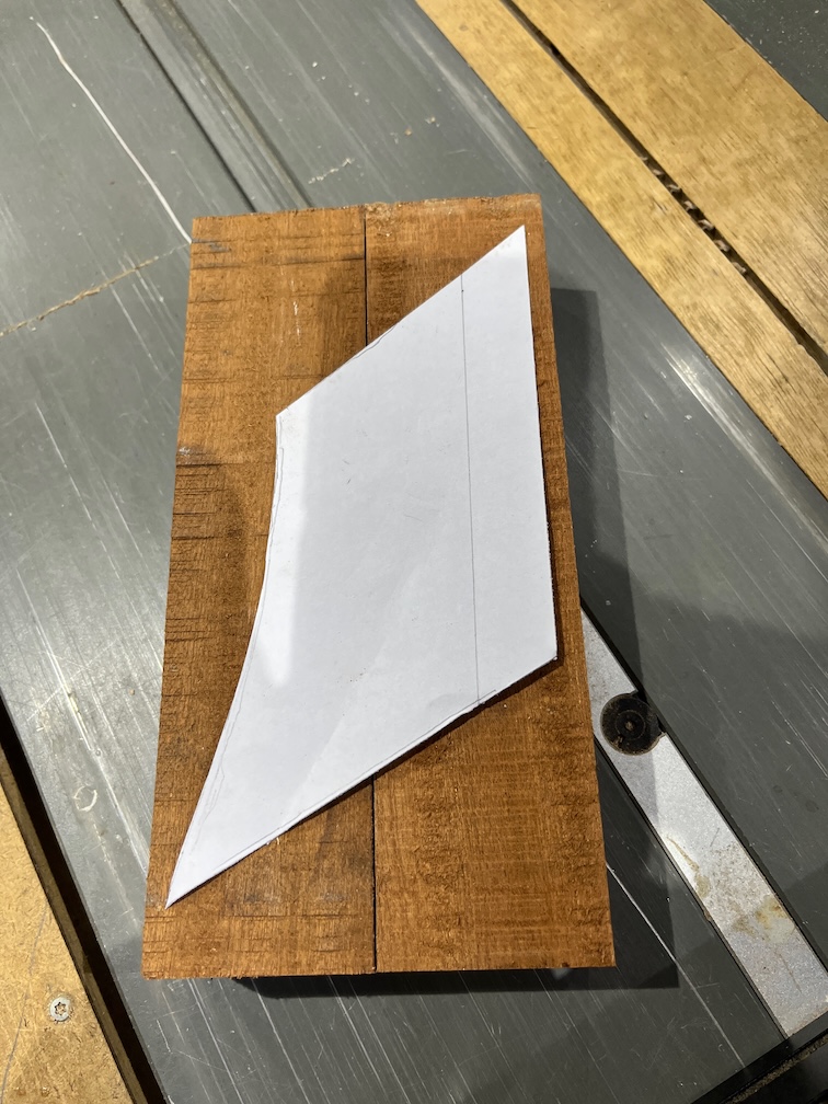
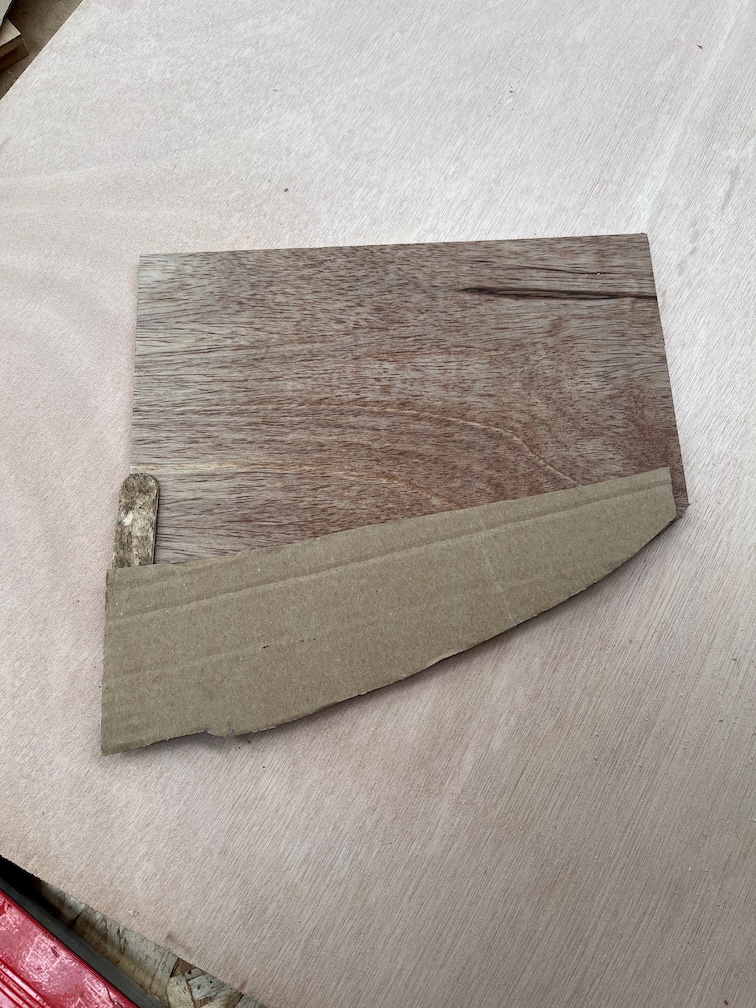
The next task is to make the new aft block section and for this I’ll need a template.
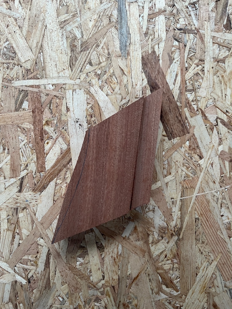
Firstly, I drew the outline on a piece of paper. Not easy to see the faint pencil lines, but they are there. The template is about 1 mm taller than the cut piece to allow for the saw cut.
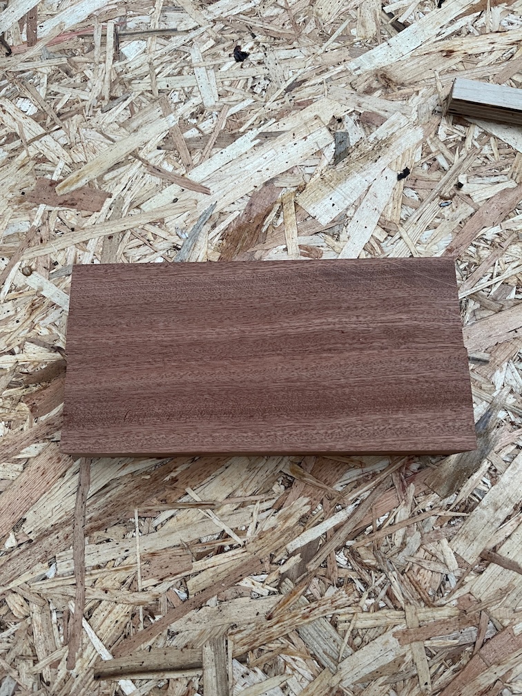
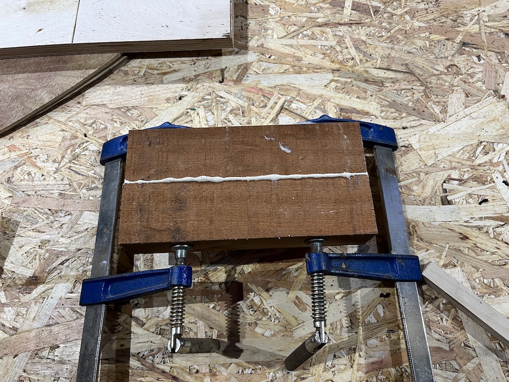
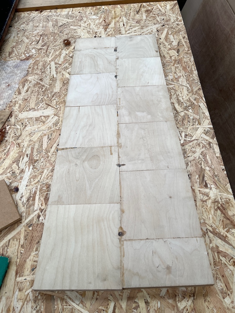
The paper template was cut out and I used it to see if I had any pieces of Sapele that would be big enough. Sadly not and two pieces were cut out and glued together.
The thickness of the Sapele is 44 mm (ish) and the aft block is 37.7 mm, probably 1 1/2″ that has been sanded down. I will run this block through the planer once the glue has dried to get it to 38 mm and smooth on both sides instead of the rough sawn finish that you can see here.
It is quite useful to note that three of the sides of the offcut are straight lines and only the aft edge is curved. This is going to make cutting the new piece out fairly straightforward, at least I hope it will.
But that’s a task for tomorrow.
Time for a cup of tea.
Finally for today, the two galley stove boards received their first coat of varnish.
The tops of the boards will receive four coat with the undersides getting two, possibly only one.
I put the diesel heater on when I went out to feed the outdoor cat this morning, meaning to give it half an hour and then to turn it off. Well, I forgot and it was nearly two hours. Still the inside of the cabin was very warm and toasty.
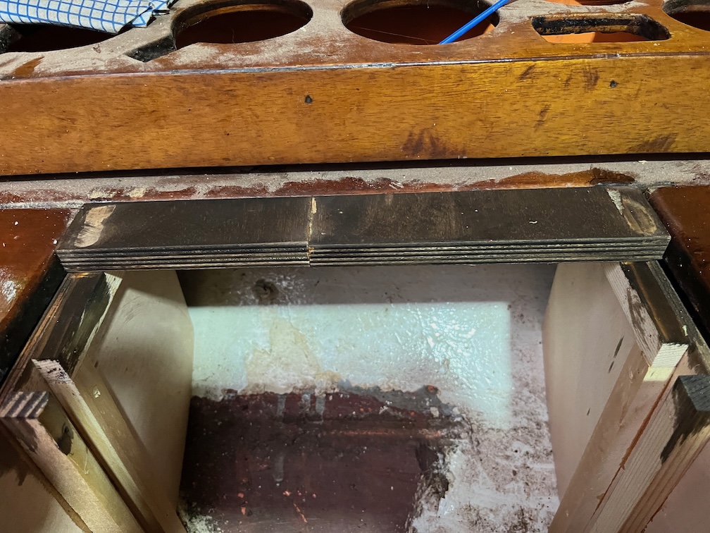
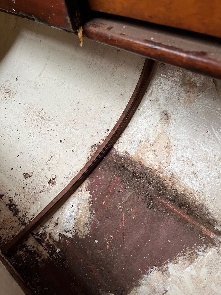
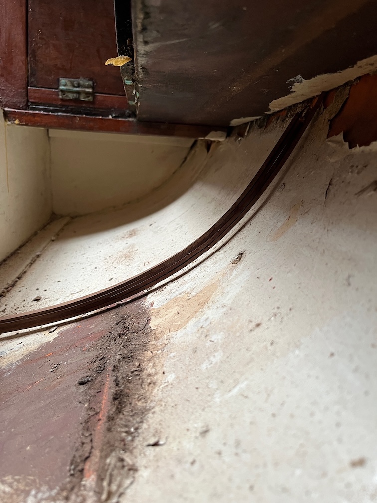
The next part of the galley stove task is to see if the laminates worked and then to make a cardboard template followed by a gash plywood template followed by the real thing.
All the cramps were loose, one had even fallen off, I presume due to them expanding in the warmth. Still, the laminates were still in position.
There is a pretty even gap under the curve but that is acceptable since there is a step at the inboard end that you can see in the top left of the above photo. It seems that the curve worked.
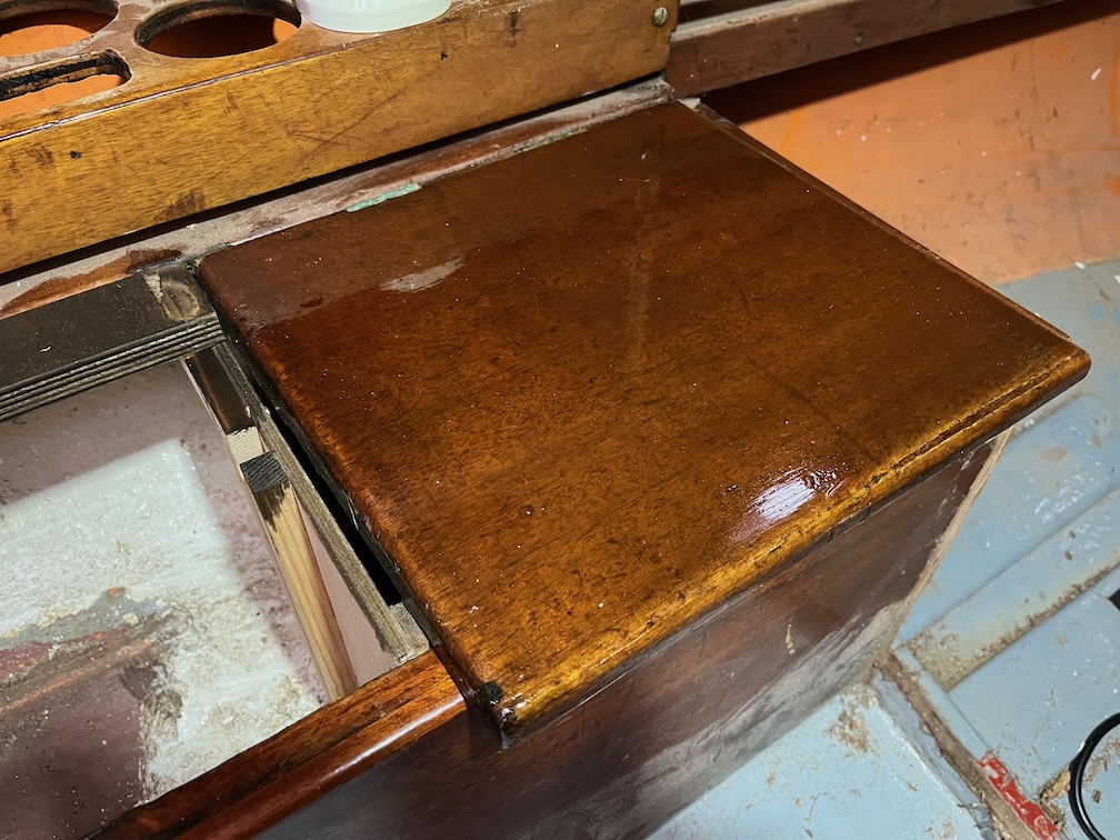
The glue up for the board and lid also worked, or so it seems.
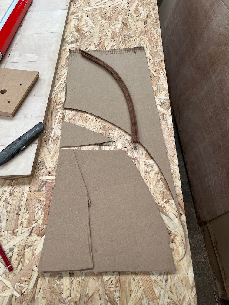
Firstly the cardboard template. The procedure is cut to the curve then cut the inboard upright to fit and then hot glue pieces to the template to make it fit elsewhere.
This is the real thing. I’ve not extended it all the way up to the outboard edge of the cup shelf, that is unnecessary.
I used cedar battens to hold the piece in place screwed but not glued so that I can remove it if required in the future.
A short length of cedar was used to secure the piece to the underside of the cup shelf. Screwed into the shelf and glued and screwed on to the work piece.
This is the “inside” face of the workpiece. Not a perfect fit, but it does not need to be. Where there is a gap under the side will be the part where the stove is stowed. Outboard of this, where there will be a small storage area, there the side is a tight fit. So, good enough.
Time for a cup of tea (and lunch).
Having done one side it is time to do the other.
I clamped two battens to the front and back of the locker so that the new side is exactly parallel to the first.
I used the gash plywood template to see how different it is going to be and as you can see, that’s not a lot of difference between the two.
I cut the bottom of the cardboard template off and hot glued that to the plywood template in the correct place.
A near perfect fit and this is the real side.
As with the first side, cedar battens were used to fix the side to the inside of the locker.
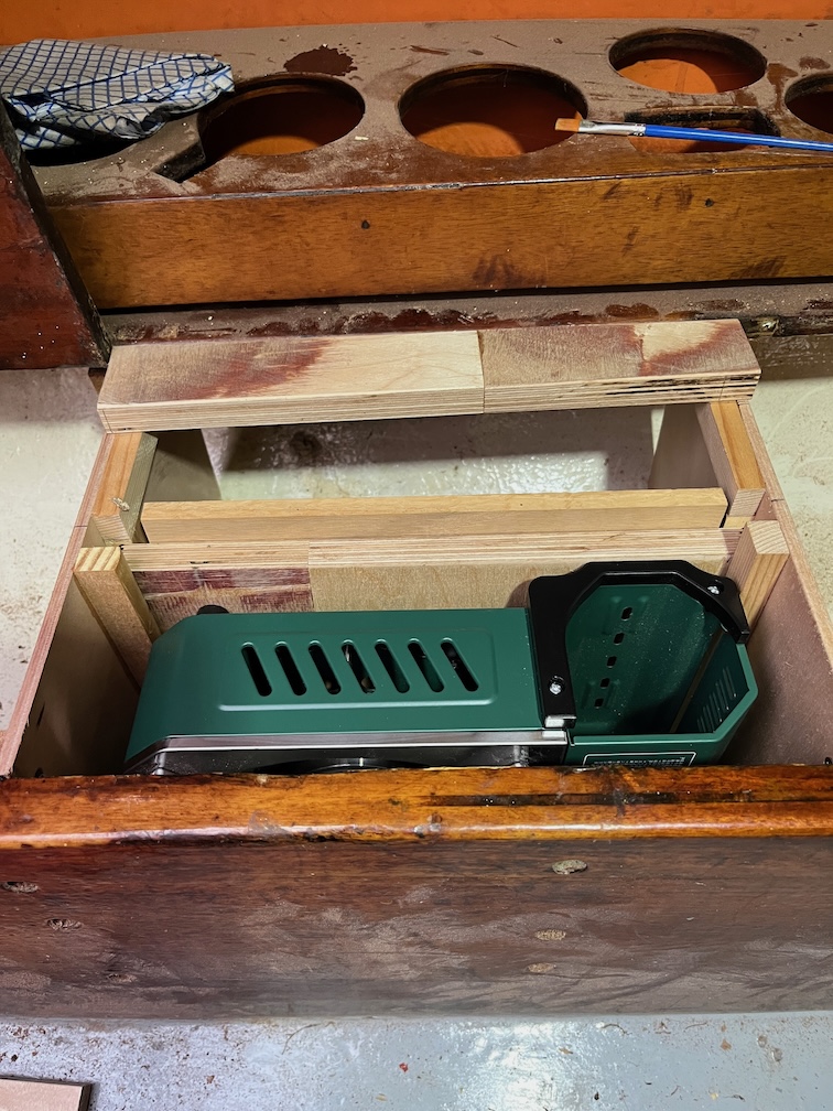
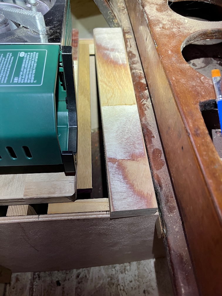
After much measuring, cutting toing and froing the galley stove has somewhere to be stowed.
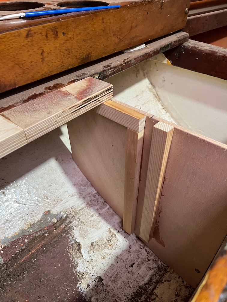
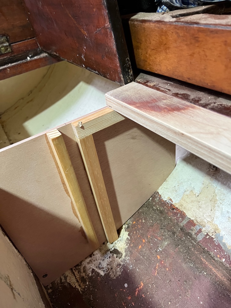
There are two vertical channels currently super-glued to the sides.
I’ll screw these in as well now that the fit has been sorted out.
At the back a lip under the galley stove goes under that back piece.
Like so and this prevents the back of the stove from lifting up should there be a sudden jerk from outside such as a passing fishing vessel.
The front of the stove is far enough out such that the heat from the flame will not be near anything it shouldn’t be !
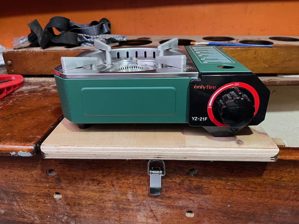
And under the front I have put in a spring latch which prevents the front from lifting up accidentally.
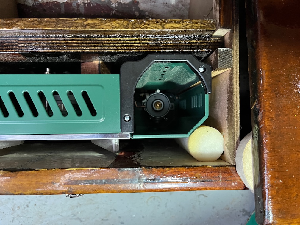
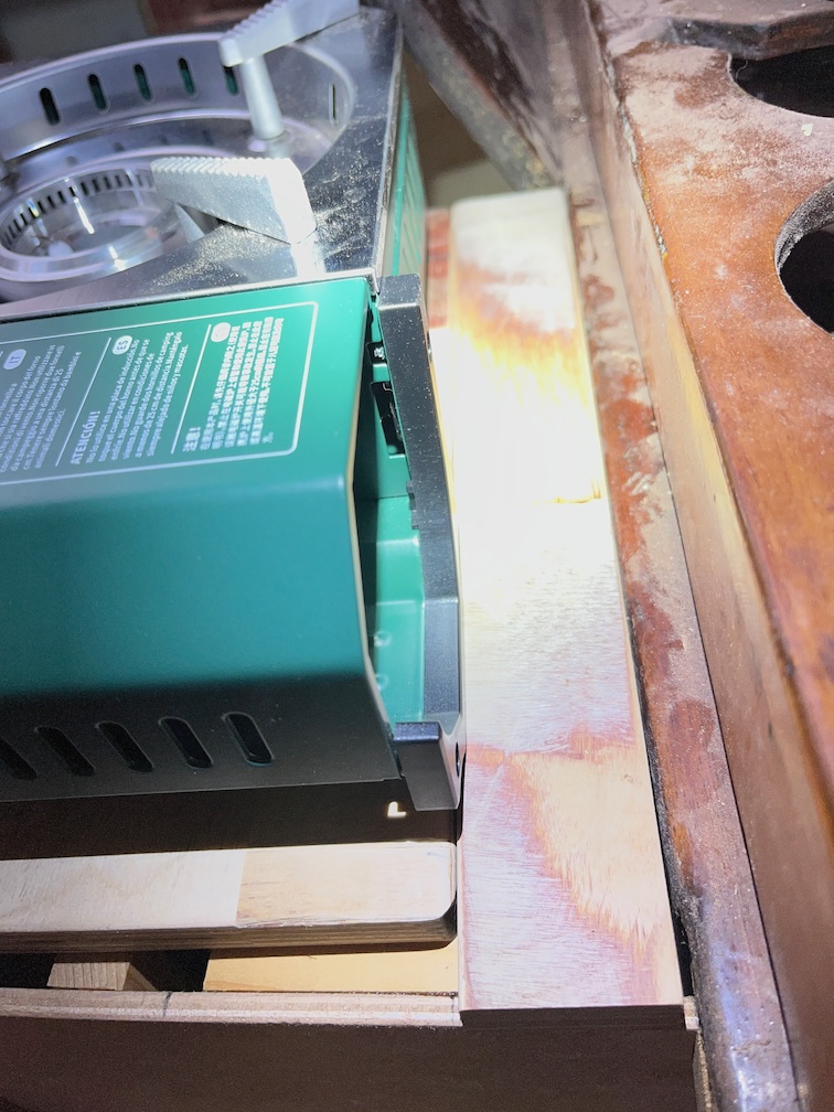
With the gas cylinder installed and the stove in place you can see that there is a small amount of space outboard of the cylinder. If there is ever a problem with the cylinder working loose under way that I’ll put some foam on the cup holder that will press against the cylinder, hopefully preventing it from working loose again. Not needed now and hopefully never.
So, everything works and all that is left to do for this task from a construction perspective is to make a lid to cover the stowed stove.