It is very cold outside today, not temperature-wise, although that is just 6º C, it is the humidity and the breeze. My fingers last just about half and hour before I have to retreat to the house to warm up, so just little things today, nothing major.
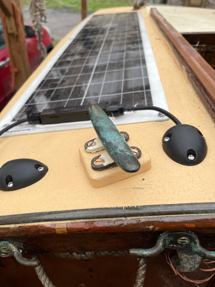
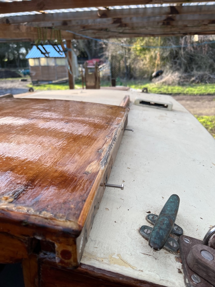
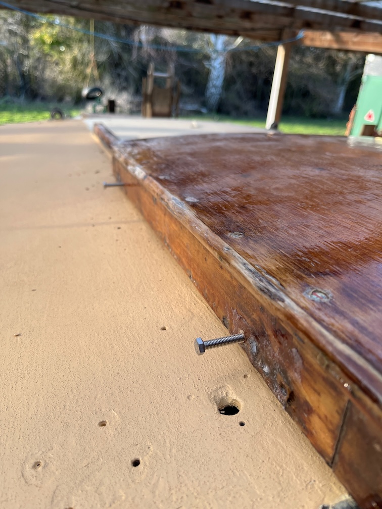
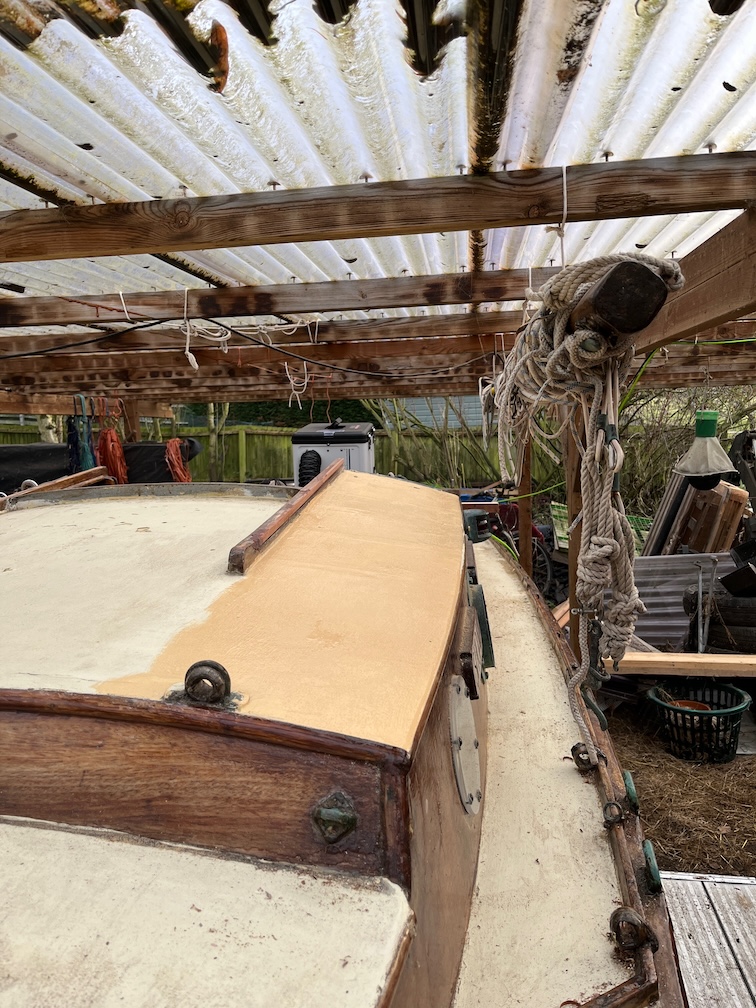
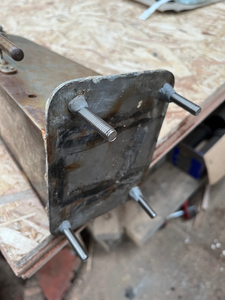
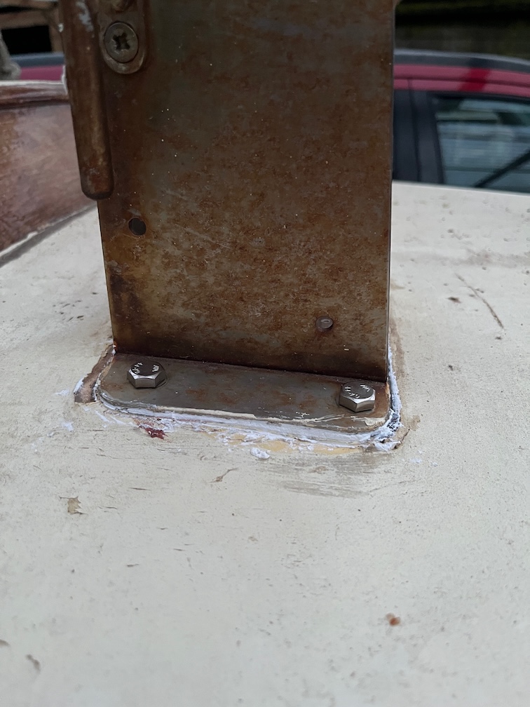
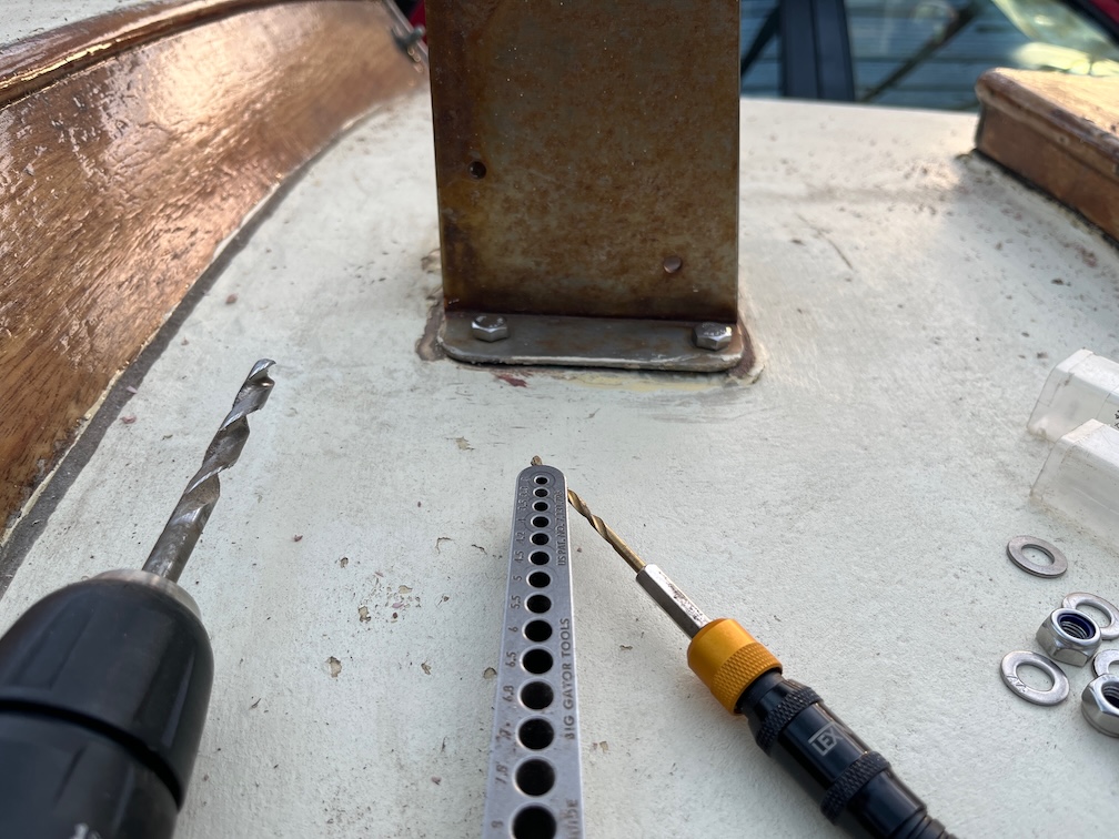
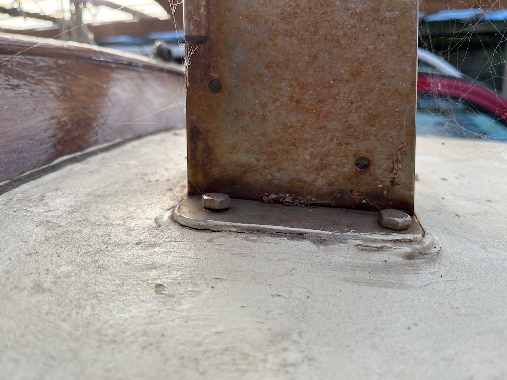
First up is the backing pad for the port side cleat. The screws I have are too short so I need to get some longer ones but I’ll leave these in for now.
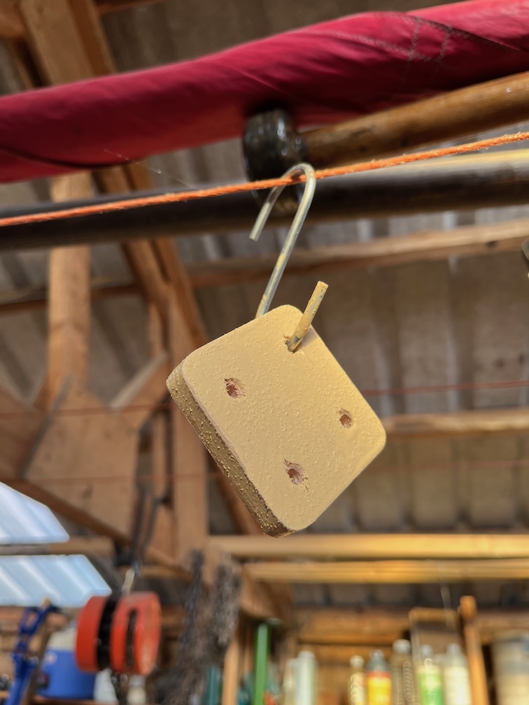
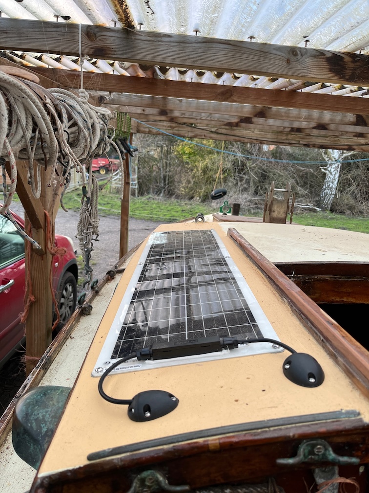
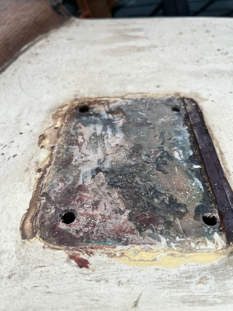
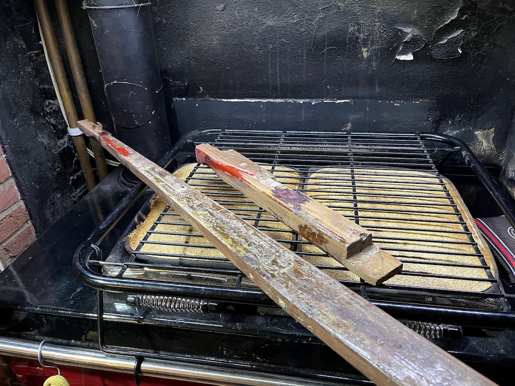
Next up is to replace the port bullseye as it is somewhat worn. I have two left over from Naiad, so it is an easy decision to make the replacement. I was just going to remove the brass screws and put in bronze replacements, but decided against this when I saw the state of the bullseye. The one on the port side has very little stress as it is simply there to guide the furling lines, however, the screws need to be replaced. I also note that the inner Lignum Vitae ring is quite worn due to the small diameter of the furling lines running through it.
I managed to get three of the screws out, two unscrewed with a screwdriver and the other two had to be drilled out, the fourth screw coming out when I removed the block from below. The old holes will be filled in the next time I mix up some epoxy, the area cleaned, sanded and painted and the new bullseye will be fitted about half an inch back from the original site. This is because the two front screws screw into the end grain of the plywood of the sloped section of the coachroof which had two problems. The first is that this could allow water ingress into the edges of the plywood and the second is that this is not strong holding.
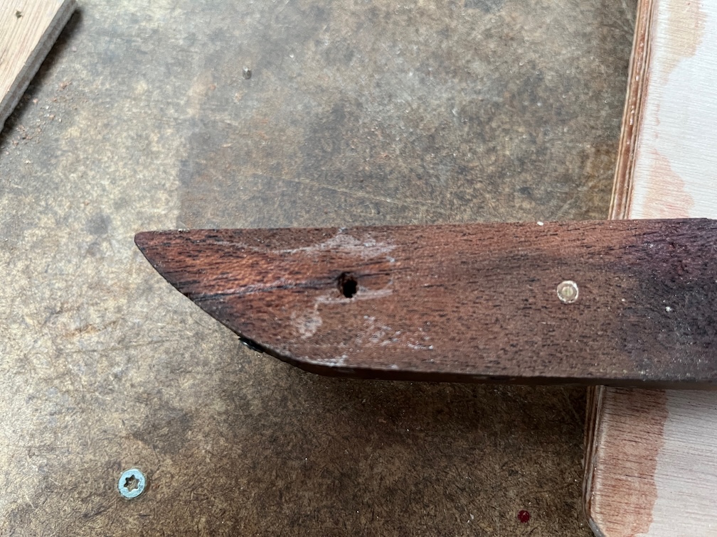
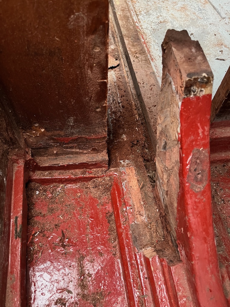
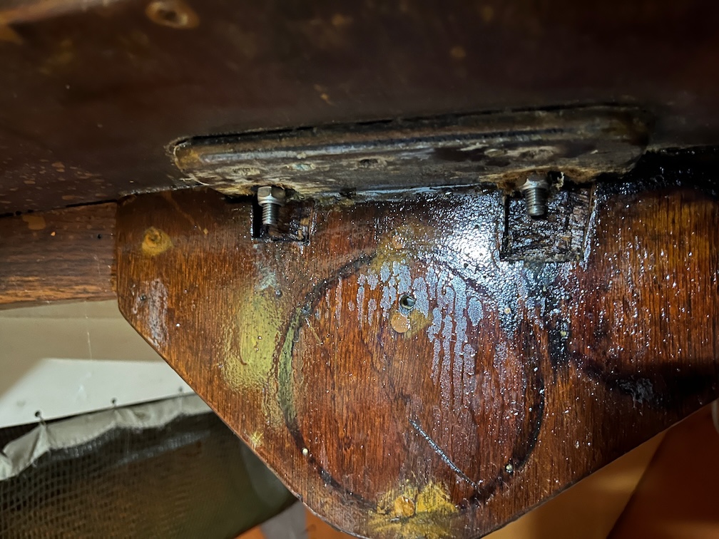
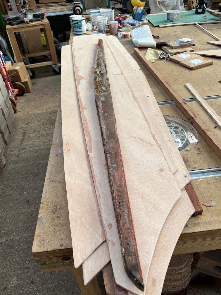
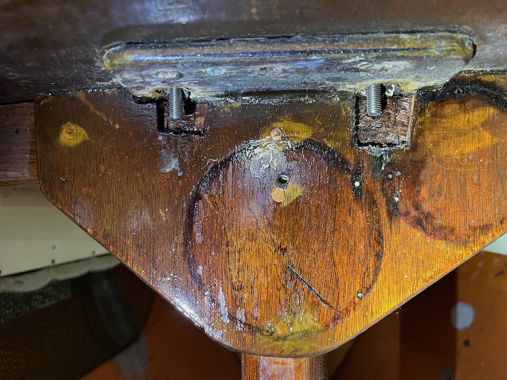
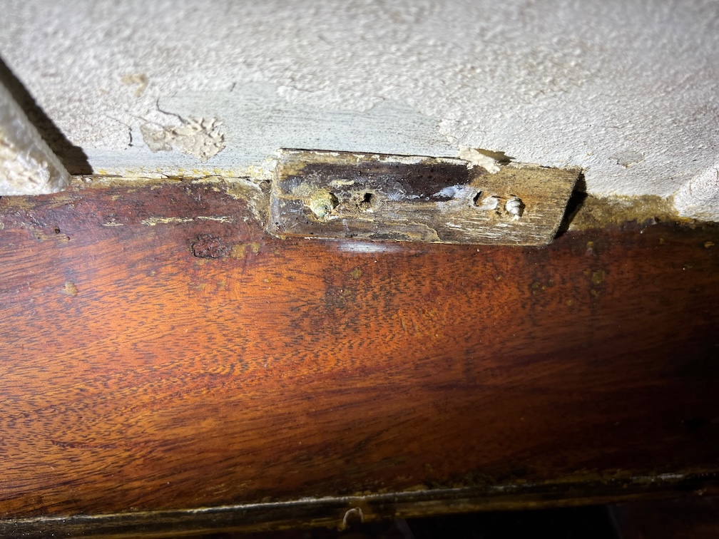
On the inside of the cabin there is a small shaped block that allows the two aft screws to screw into more than just the thickness of the coachroof, however it is to small and thin and has some water damage as evidenced by the darkened wood.
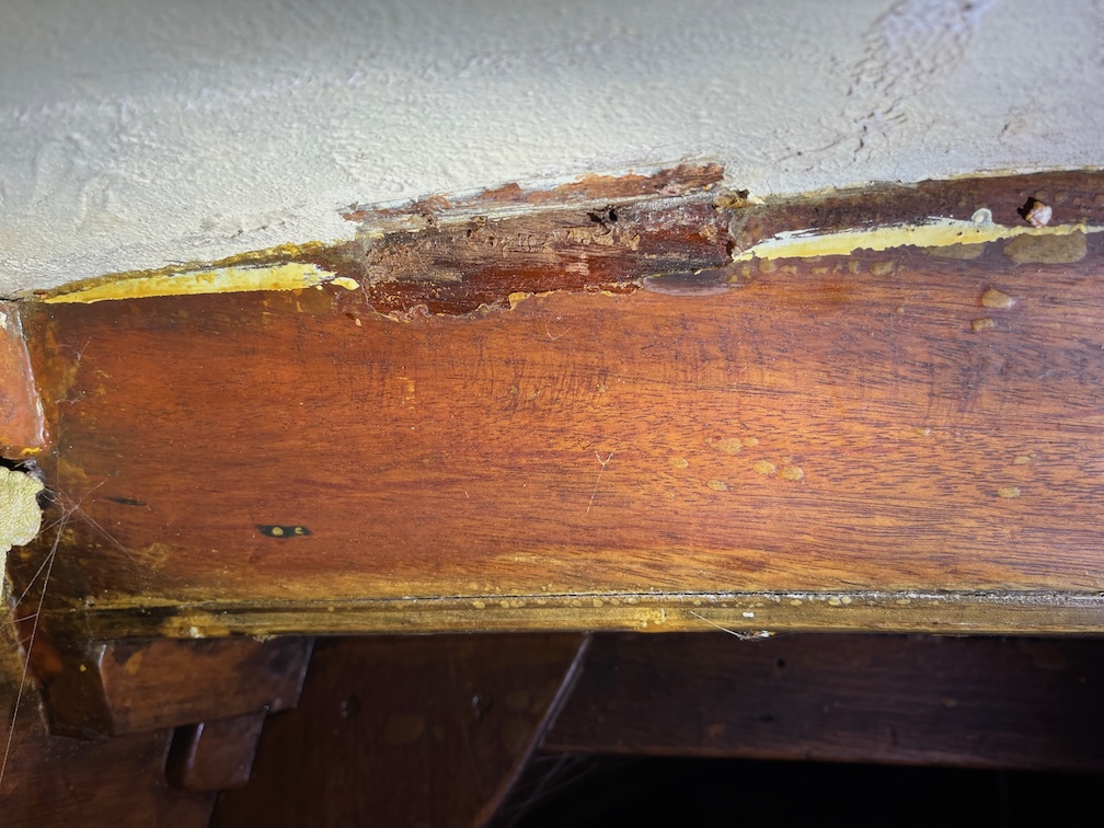
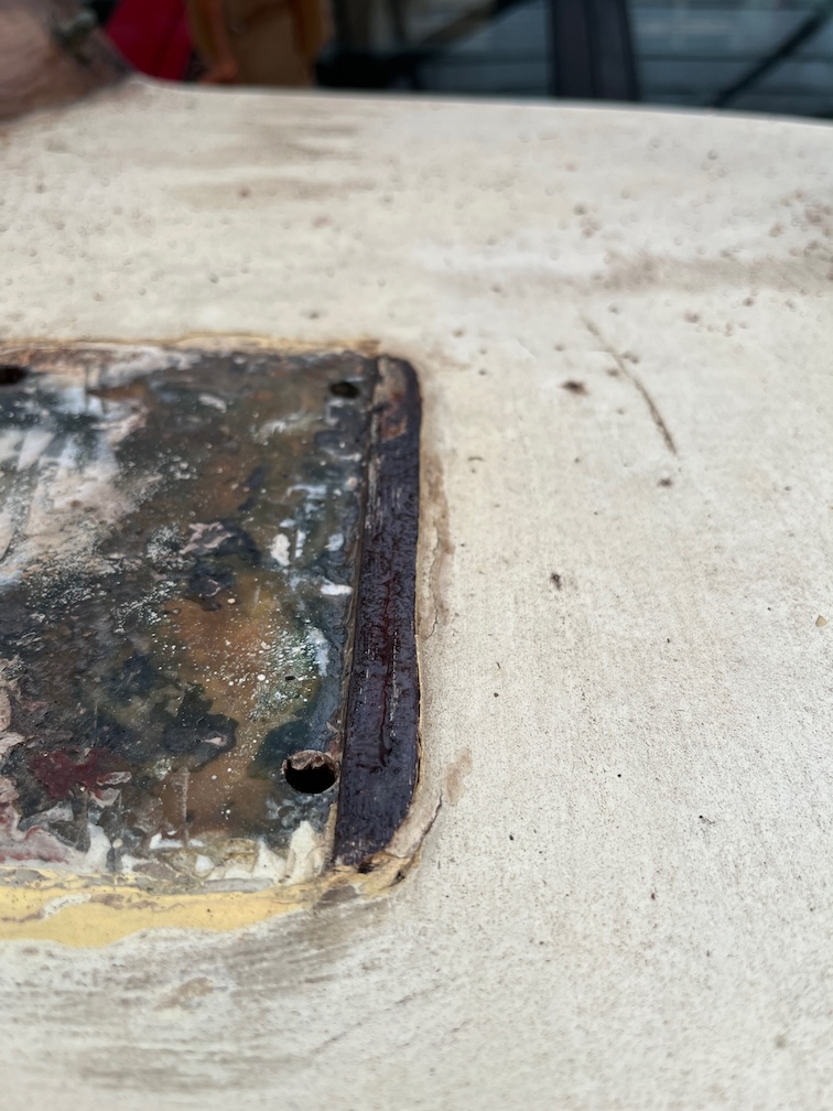
This is where the removed block is sited and it does look like there may be some water damage to the plywood from the front, right screw as you can see from the darkened area.
Still, on this side the stress on the bullseye is not great but moving the bullseye and block aft will allow a larger block to be used and for all four screws to be screwed into this thicker and stronger block.
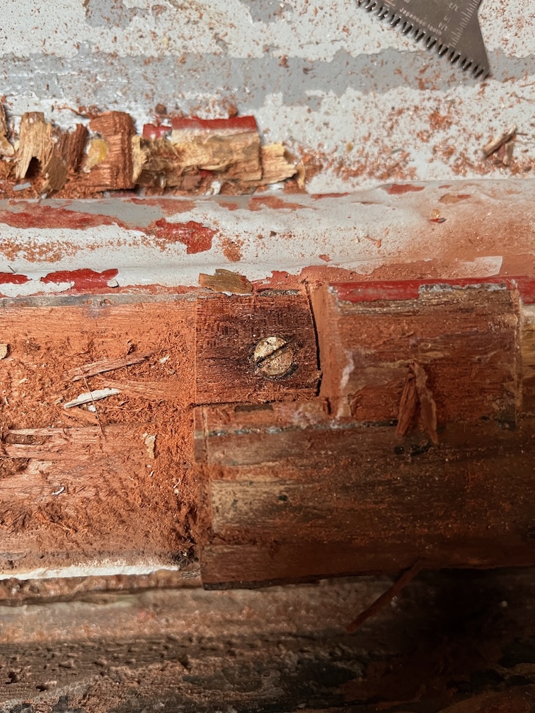
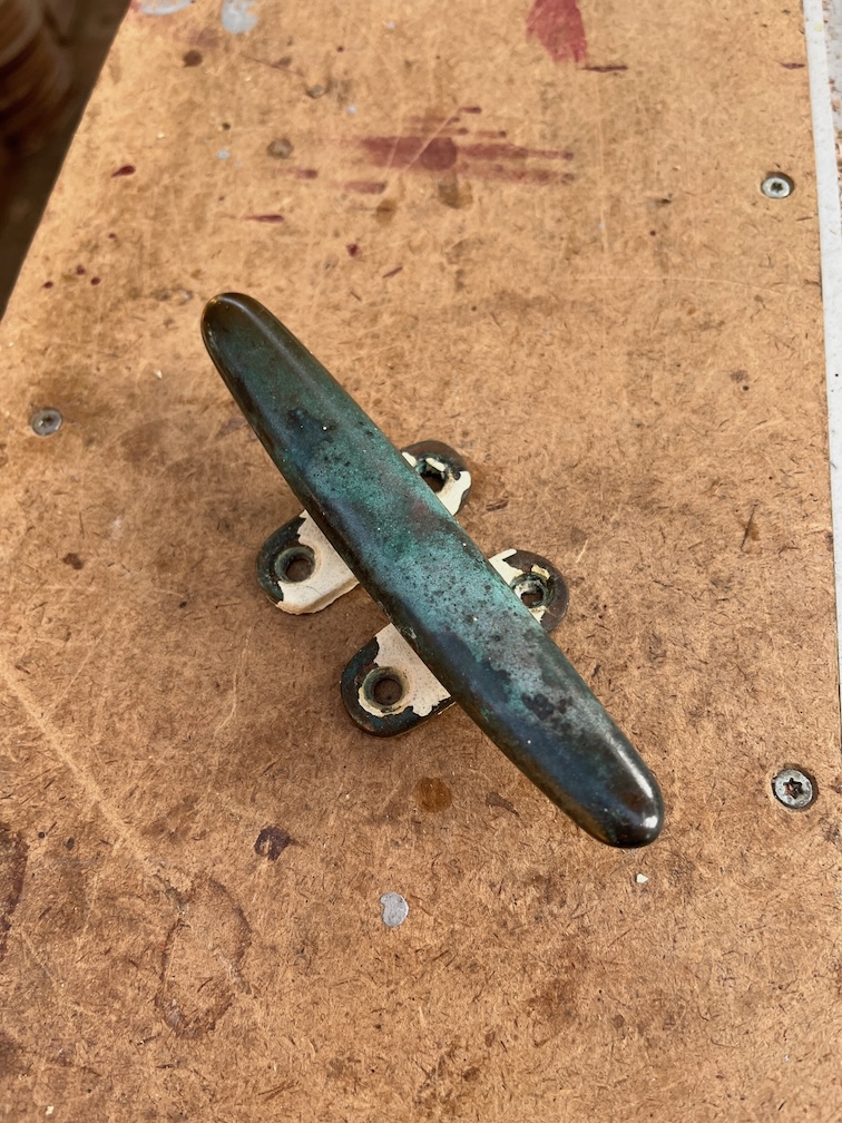
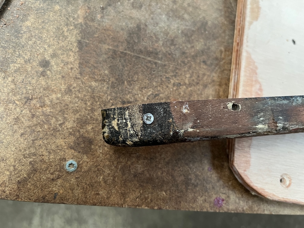
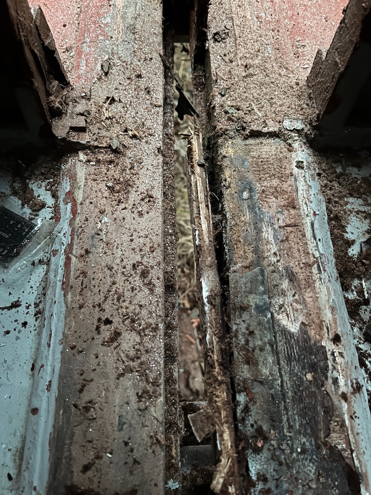
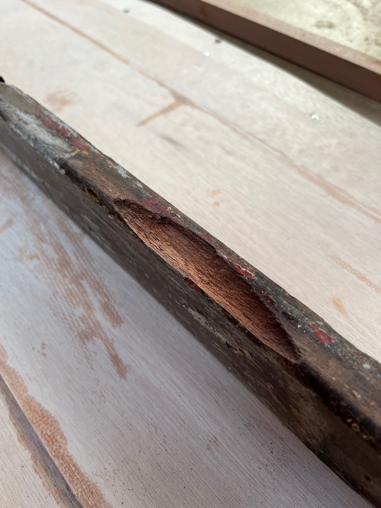
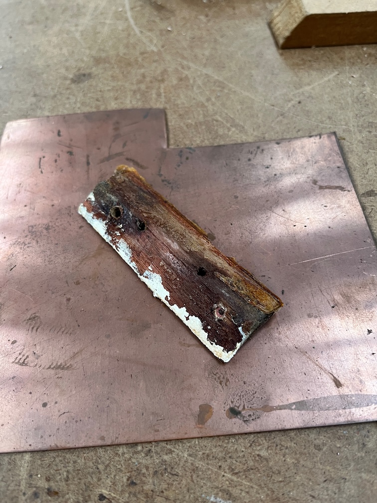
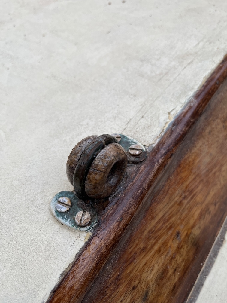
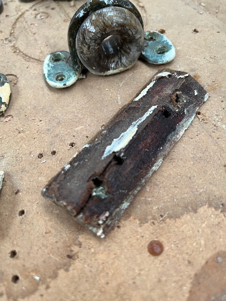
This is the block on the starboard side of the cabin and here the story is a little different. The strain on the bullseye above this block is upward and aft as the topping lift runs through it. The screws have partially disintegrated as you can see from the left screw point here, it is covered in verdigris and I expect that when it is removed, these screws will be mainly copper. This block will be replaced, moved aft as for the port side and the screws replaced with bronze.
I won’t know if the bullseye this side needs to be replaced until I take it off and inspect it, which will be as soon as my hands warm up !
Time for a cup of tea.
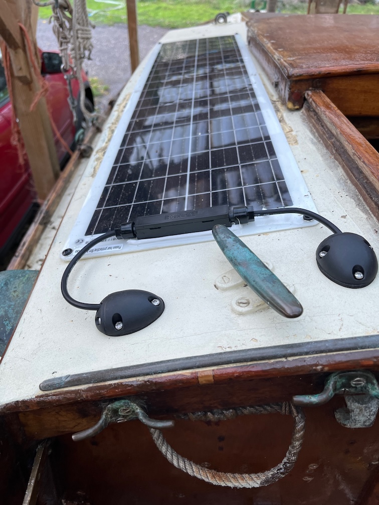
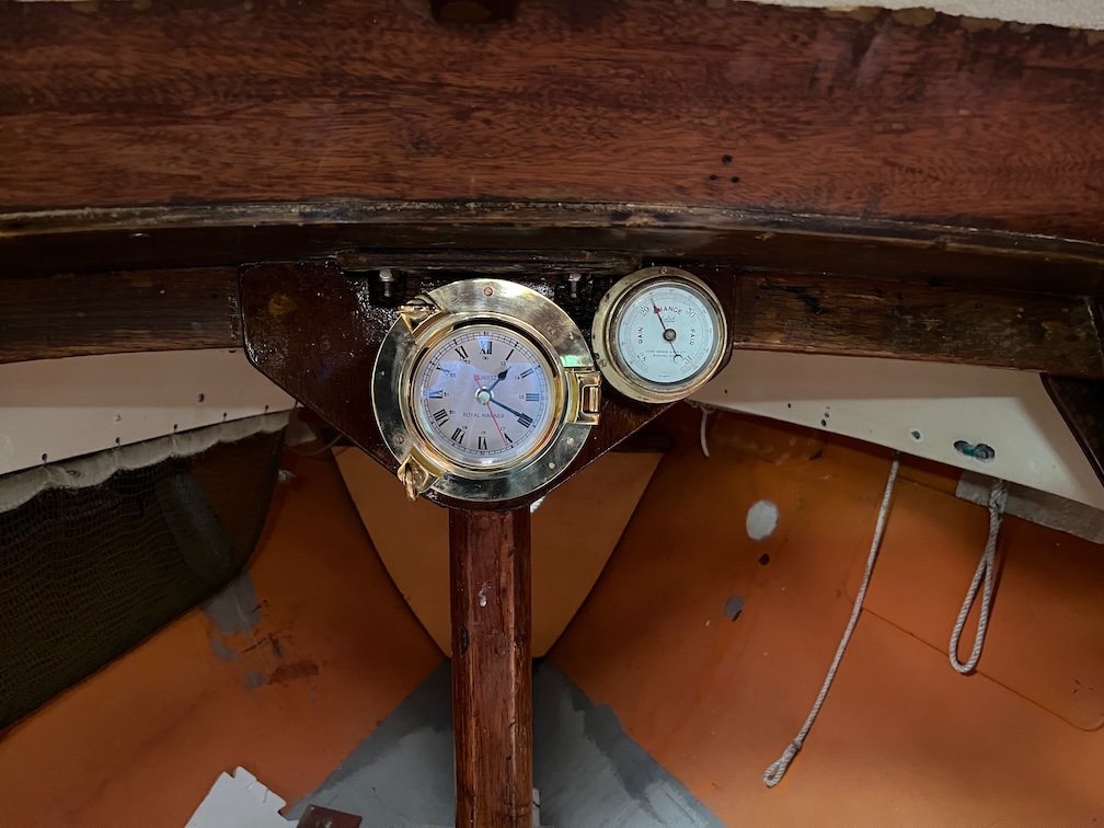
Having warmed my fingers up and drunk my tea, I went back to Shoal Waters and took a look at the starboard bullseye.
You can see that the brass screws have been replaced with stainless indicating that the brass ones were too far gone and possibly even let the bullseye fly loose whilst in use due to the upward tension.
The bullseye itself looks to be in fairly good condition as the line running through it is a lot larger than the furling lines through the other one, but I think I’ll replace it as the topping lift is, as just mentioned, not a thin line and this is one of the smaller internal diameter bullseyes whereas the ones I have spare are larger.
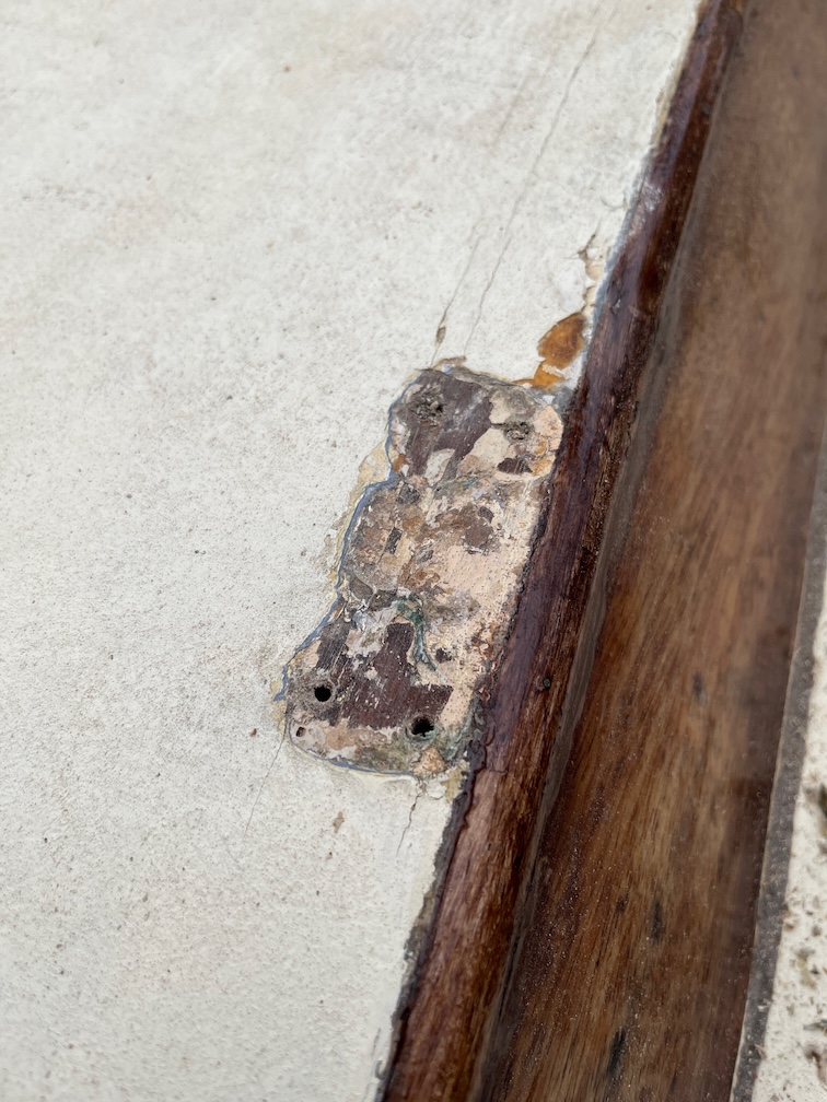
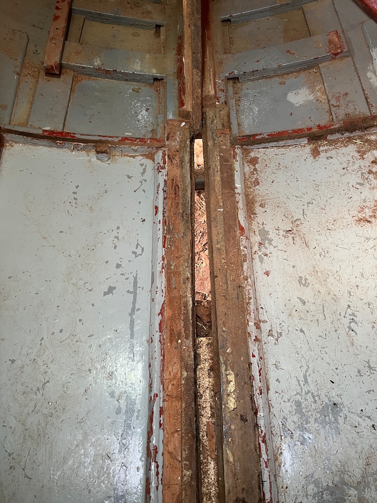
Removing the screws and bullseye shows a fair amount of sealant under the fitting and the plywood looks to be in fair condition.
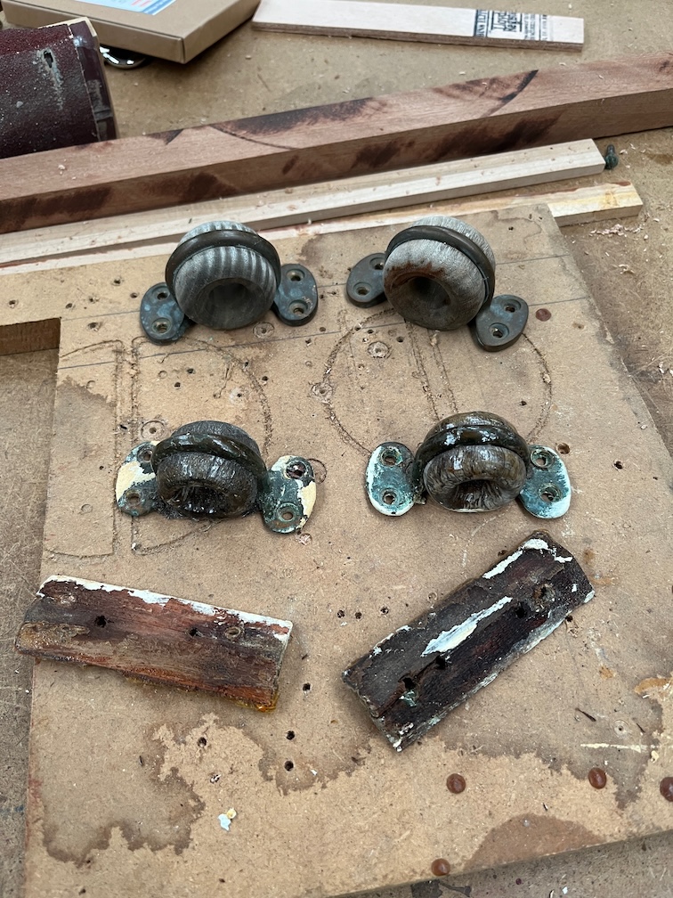
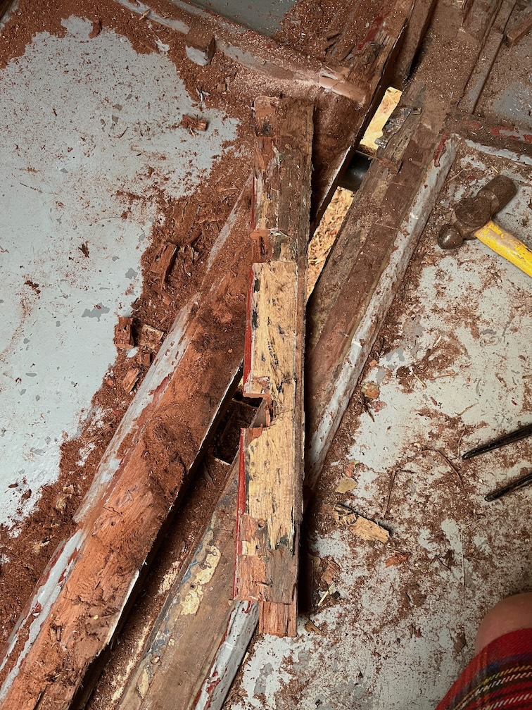
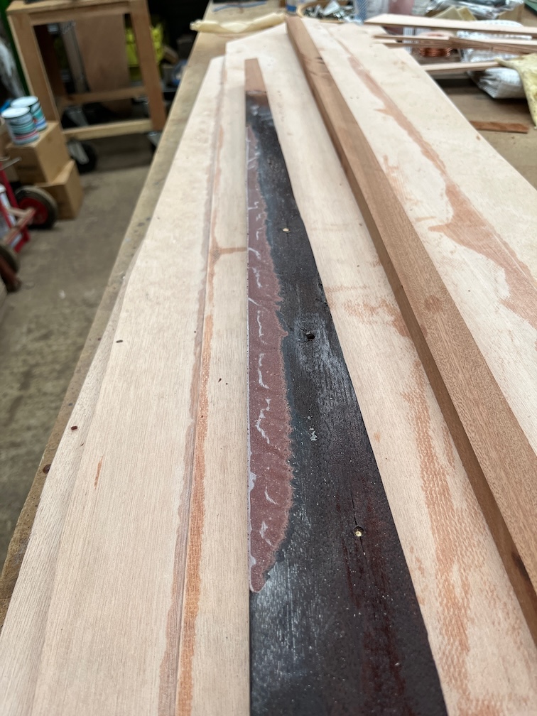
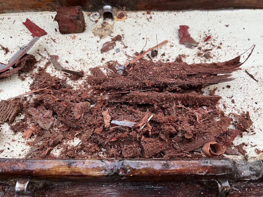
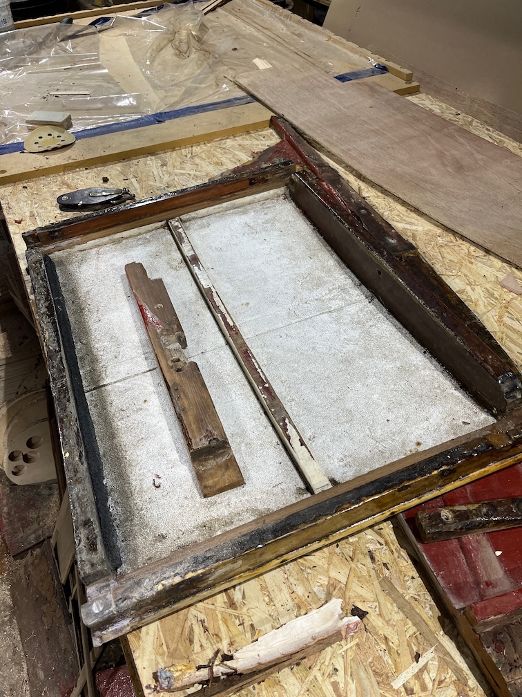
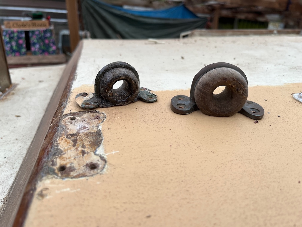
I took that block out from inside and here are the blocks, old and new bullseyes.
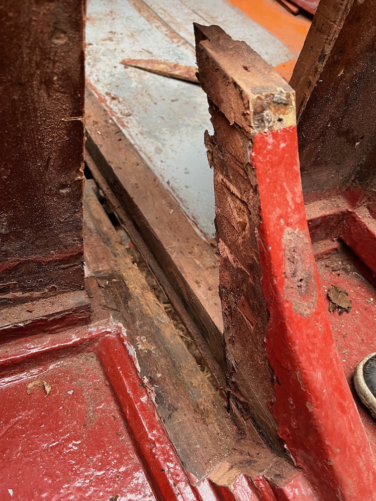
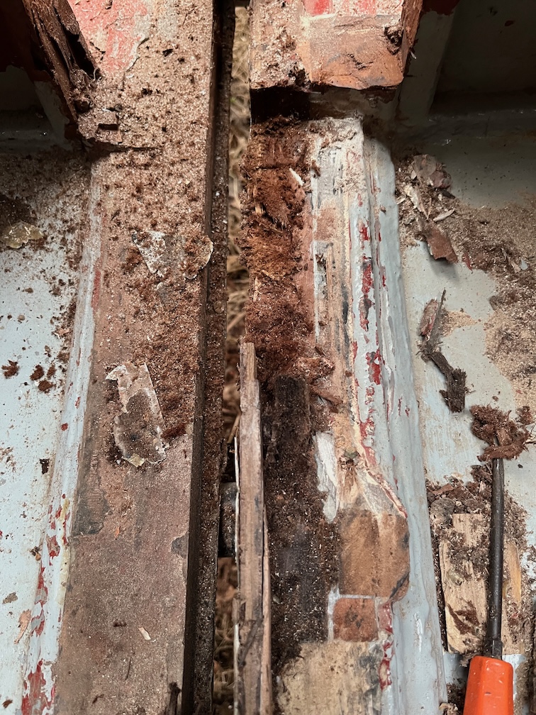
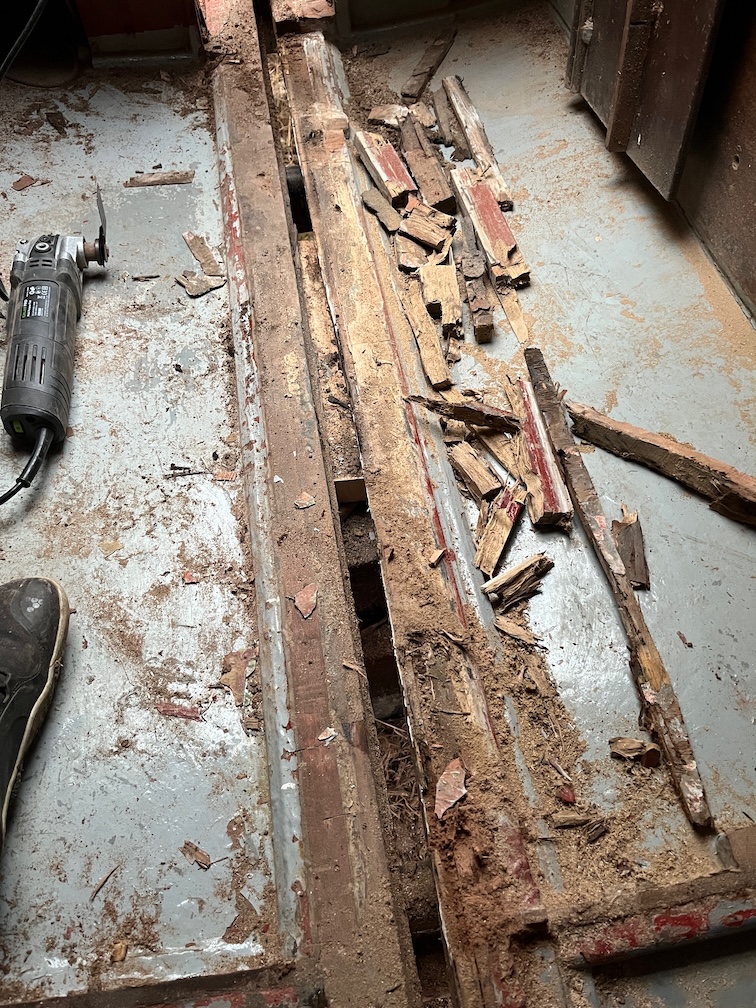
You will notice that not only is the starboard block wet and much darker than the one from the port side, but is is also split through the screw hole. So whether or not the bullseye needed to be replaced, the block underneath certainly needs to be replaced as it is pretty useless as is.
I’m hoping that the plywood of the coachroof in this area is still sound, I will have to take a closer look from inside at a later date. From the outside the plywood looked sound on both sides, but I’ve not checked the inside yet.
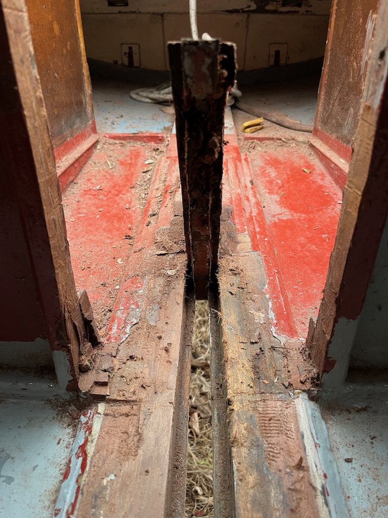
Thinking about the load on the starboard bullseye, I will probably make the new block substantially wider than the original to spread the load across more of the coachroof. There is an argument that suggests that the entire joint should be strengthened from one side to the other as I did in Naiad, but that would mean laminating a new beam in situ. I have the wood, epoxy and skills to do this but it is quite a lot of work that I don’t really need to do at the moment. Wider blocks should do the trick, so I think I’ll put this on the wish list for another off-season.
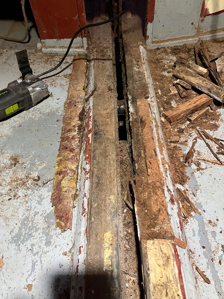
Conveniently, the angle on the forward side of the blocks is 45º, which means that this can be cut on the table saw. However, the coachroof is also curved.
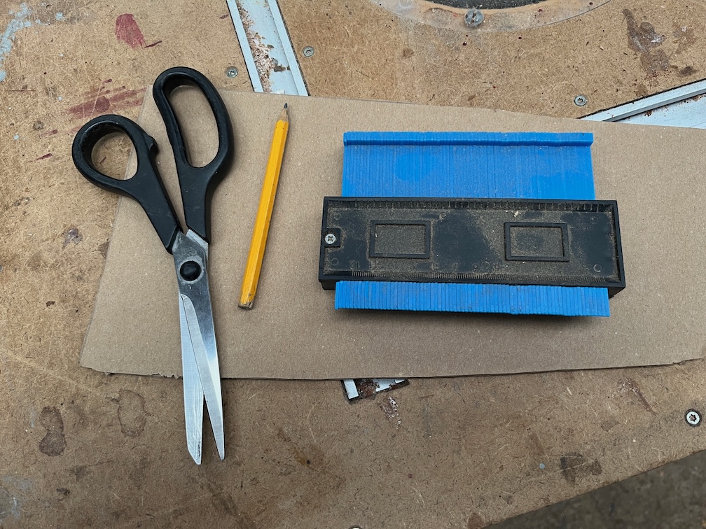
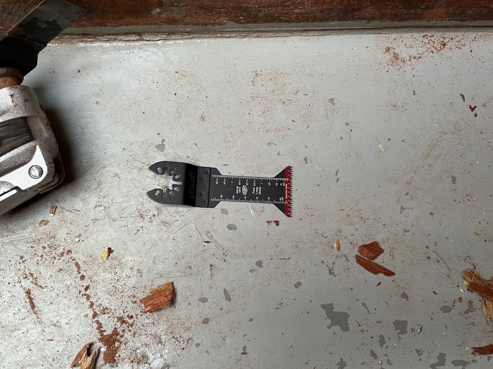
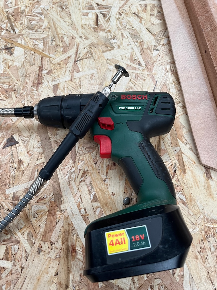
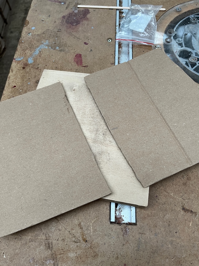
So armed with the appropriate tools I measured the curve using a piece of cardboard for a template. From this template I cut a second template that mimics the coachroof, to use for shaping the blocks.
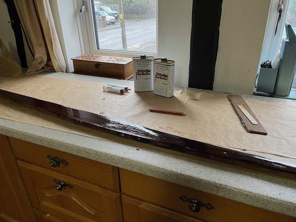
However, the curve is too slight to be able to cut accurately, so I’ll do this a slightly more messy way that will give an exact result. That is to cover the top side of the block with thickened epoxy with cling film on top of that and press the whole thing into place and keep it there with a prop from below. Once the epoxy has cured the block is taken down, the cling film removed and any squeeze out trimmed off.
The problem is that it is currently too cold for epoxy, so this will have to wait until either the weather warms up or I warm up the inside of the cabin with the new heater. Guess which one I’ll be doing!
But not today.
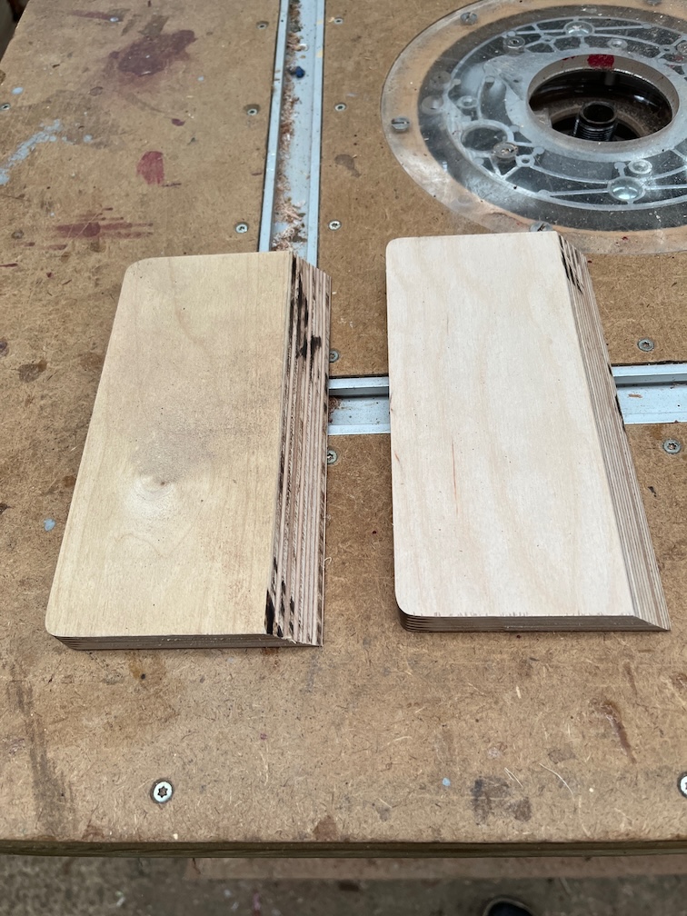
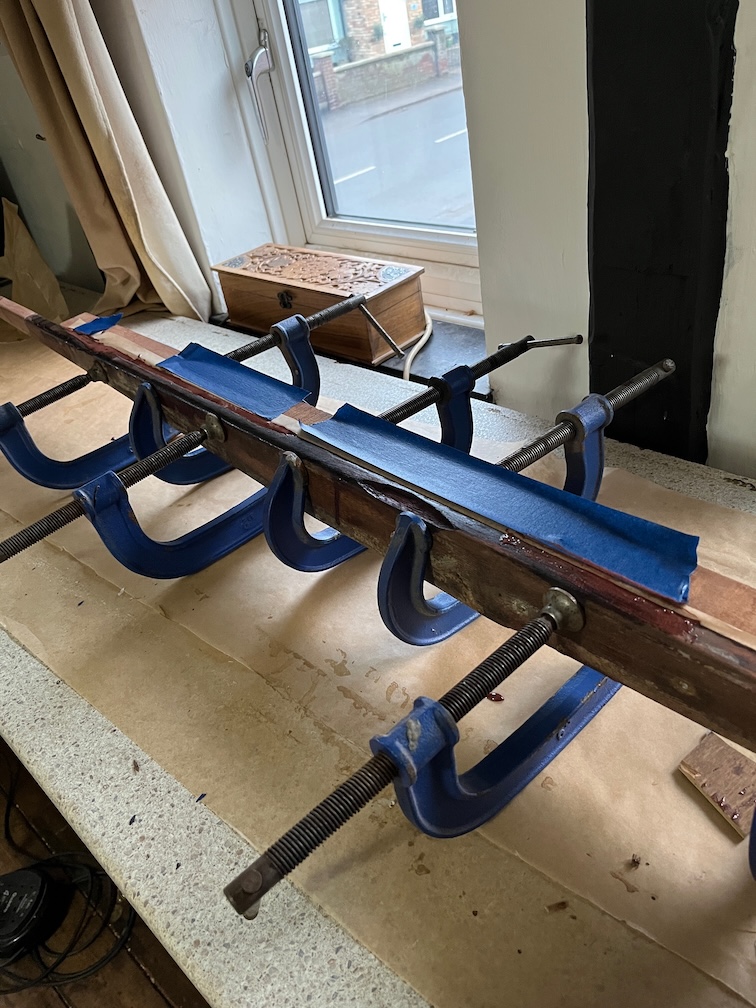
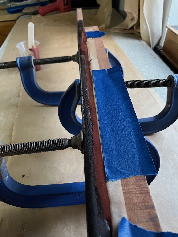
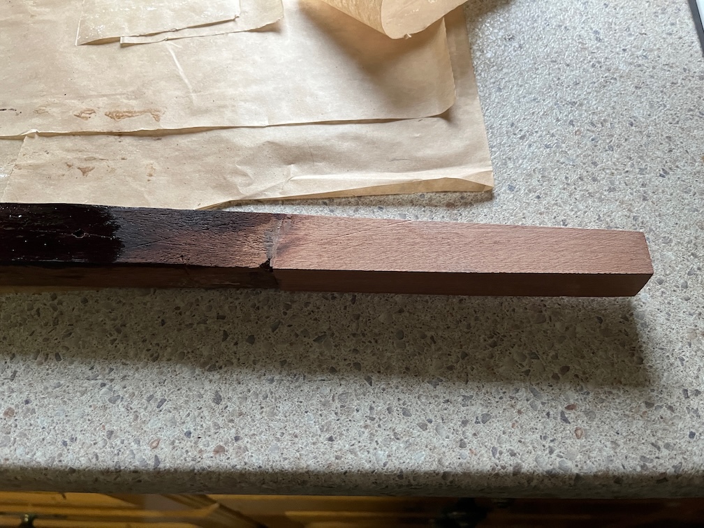
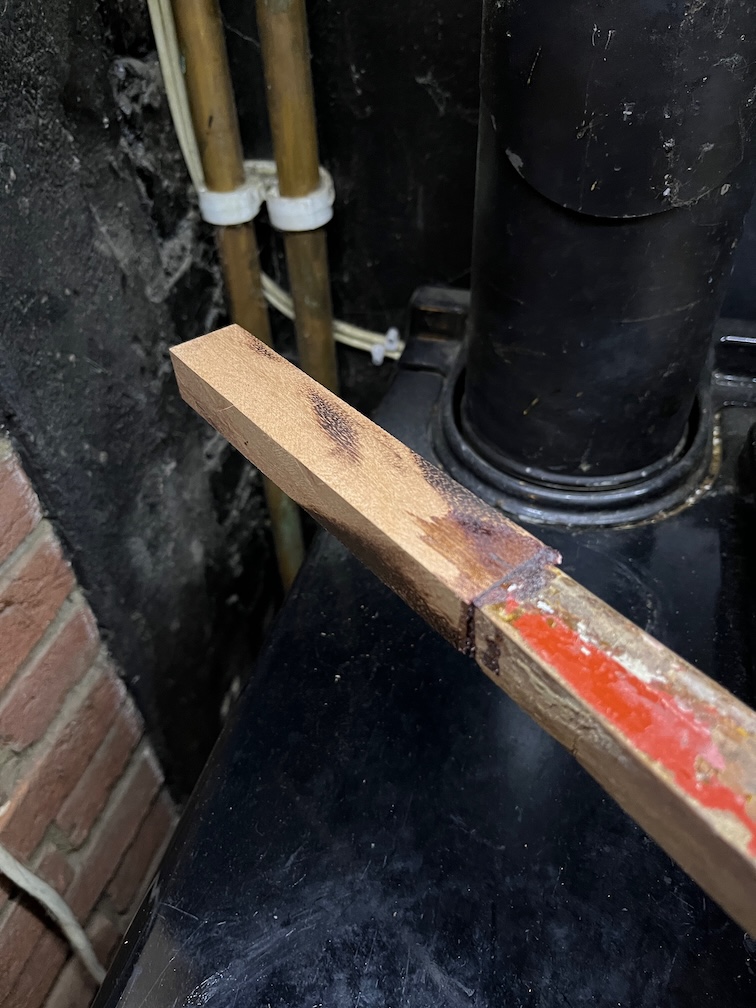
I did take the time to cut two pieces of Baltic Birch plywood that will be used for the blocks and round off what will be the visible edges. So as soon as the temperature allows, I’ll get the epoxy filler applied.
That’s all for today.
Time for a cup of tea.