2026-02-10 – Centerplate Case Aft Block I

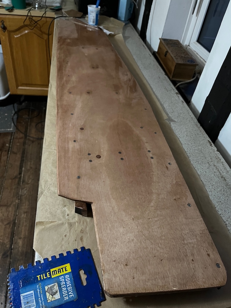
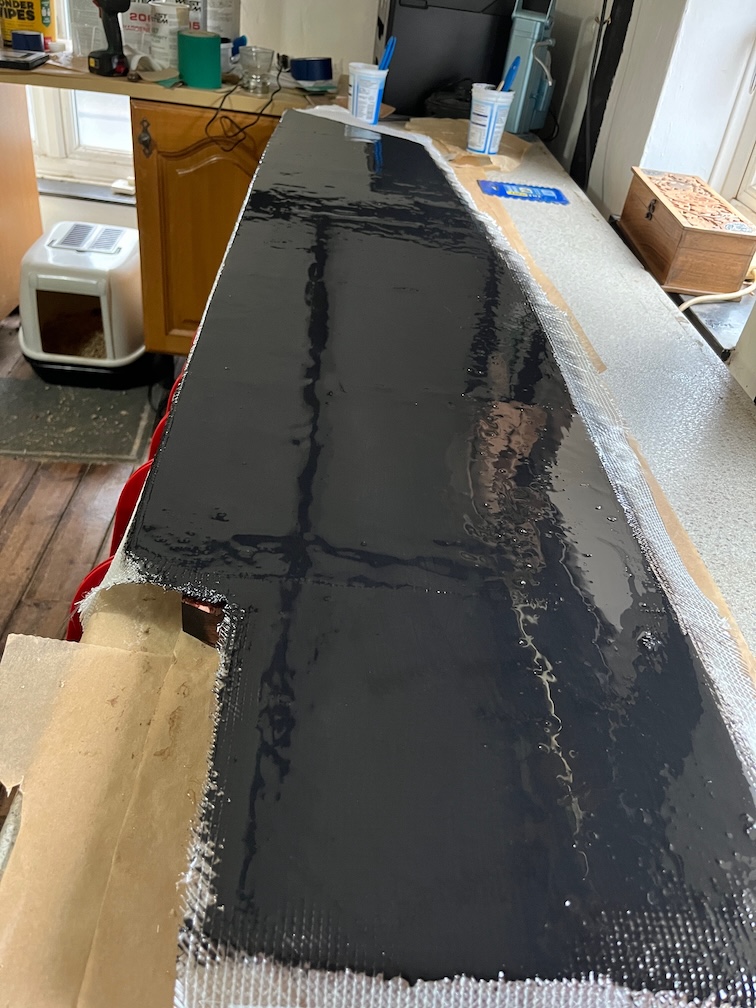
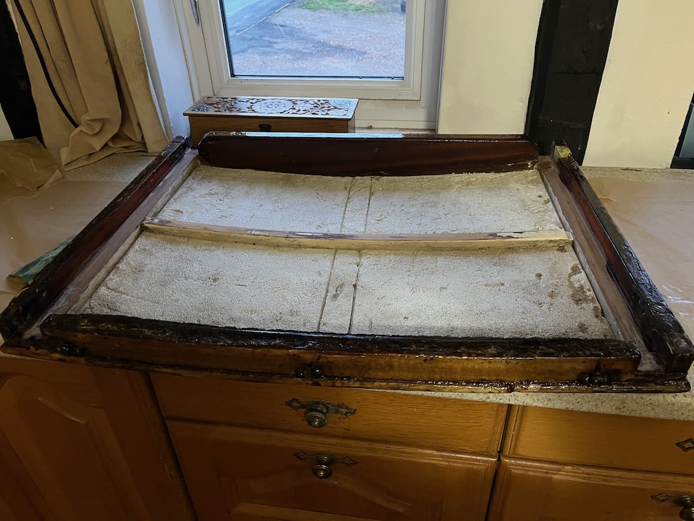
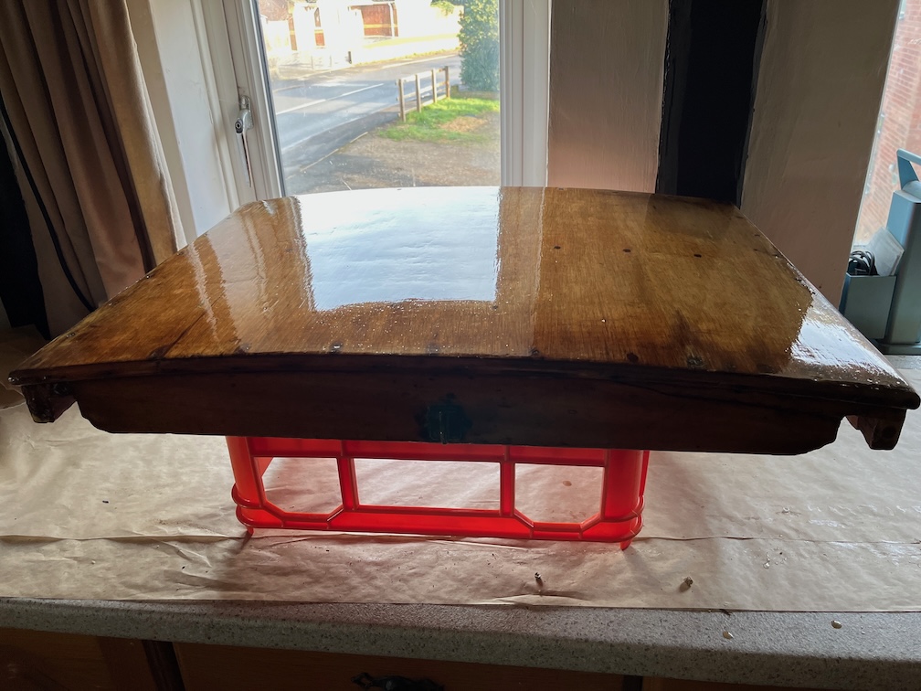
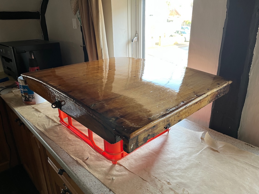
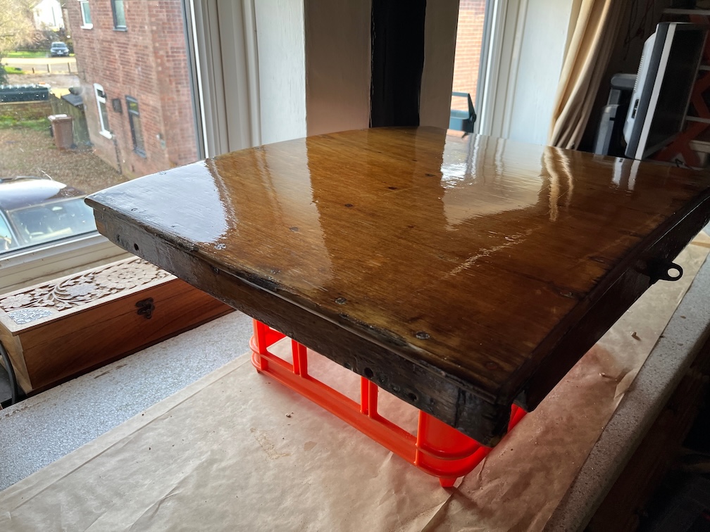
The first small task on the list today was applying a second coat of varnish to the top side of the galley stove boards.

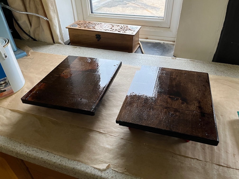
The boards are starting to look a lot more shiny than for the first coat as that soaked into the wood. This one did not, or not so much, since the first coats sealed most of the wood grain.

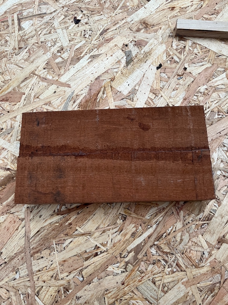
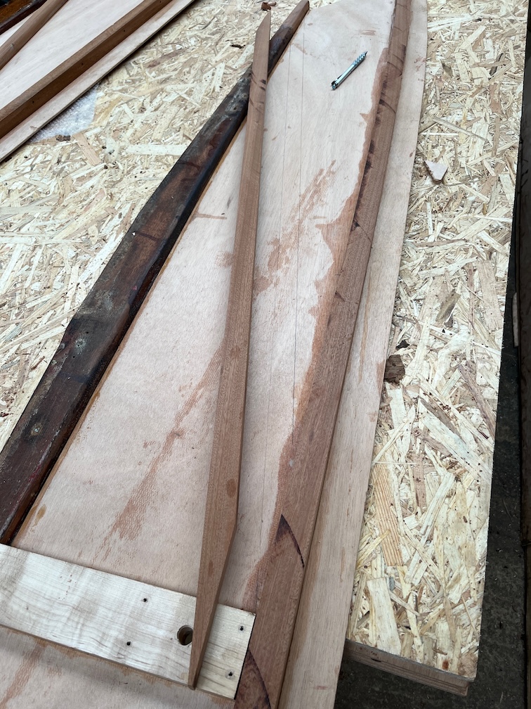
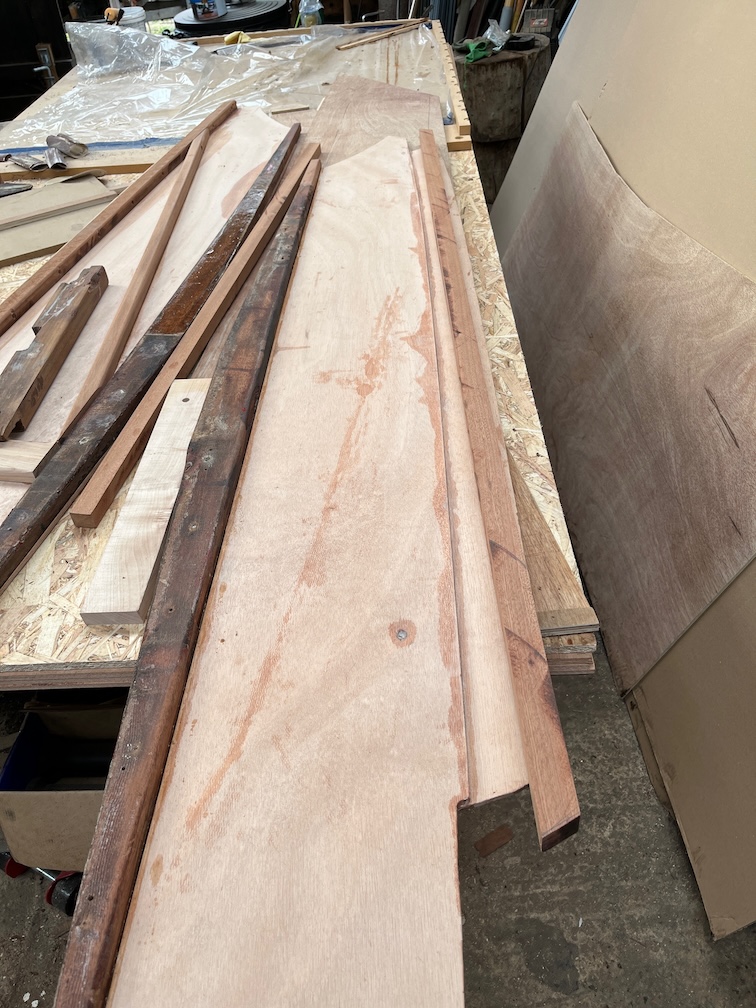
The glue up of the wood for the new top section of the aft block seems to have gone well, so it was out to the workshop to remove the rough surfaces.

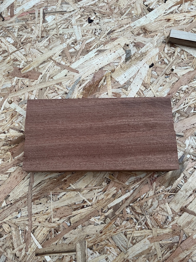
The planer puts a lot of pressure and stress on the wood as it is cutting off wood from the surface and if a joint is not particularly good, then this usually results in the join splitting apart. In this case it didn’t so all is well there. I planed the wood down to it’s final thickness and now it is ready to go.

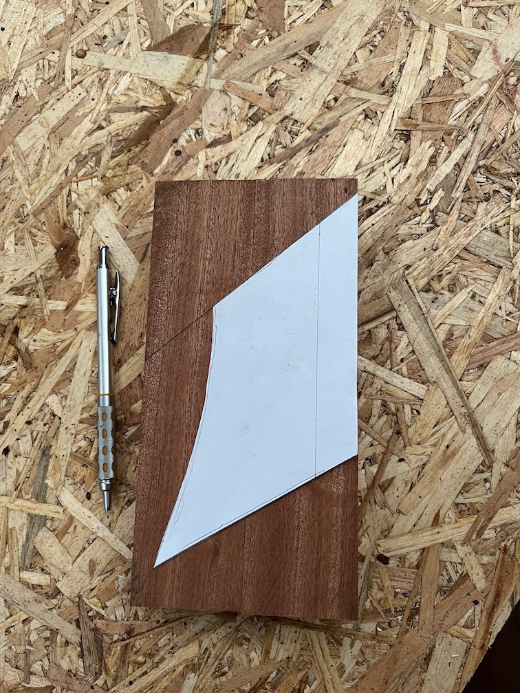
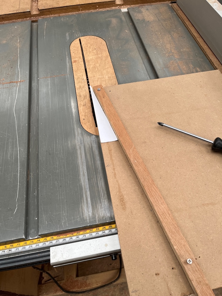
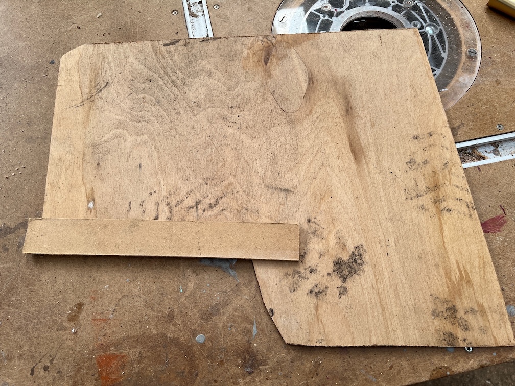
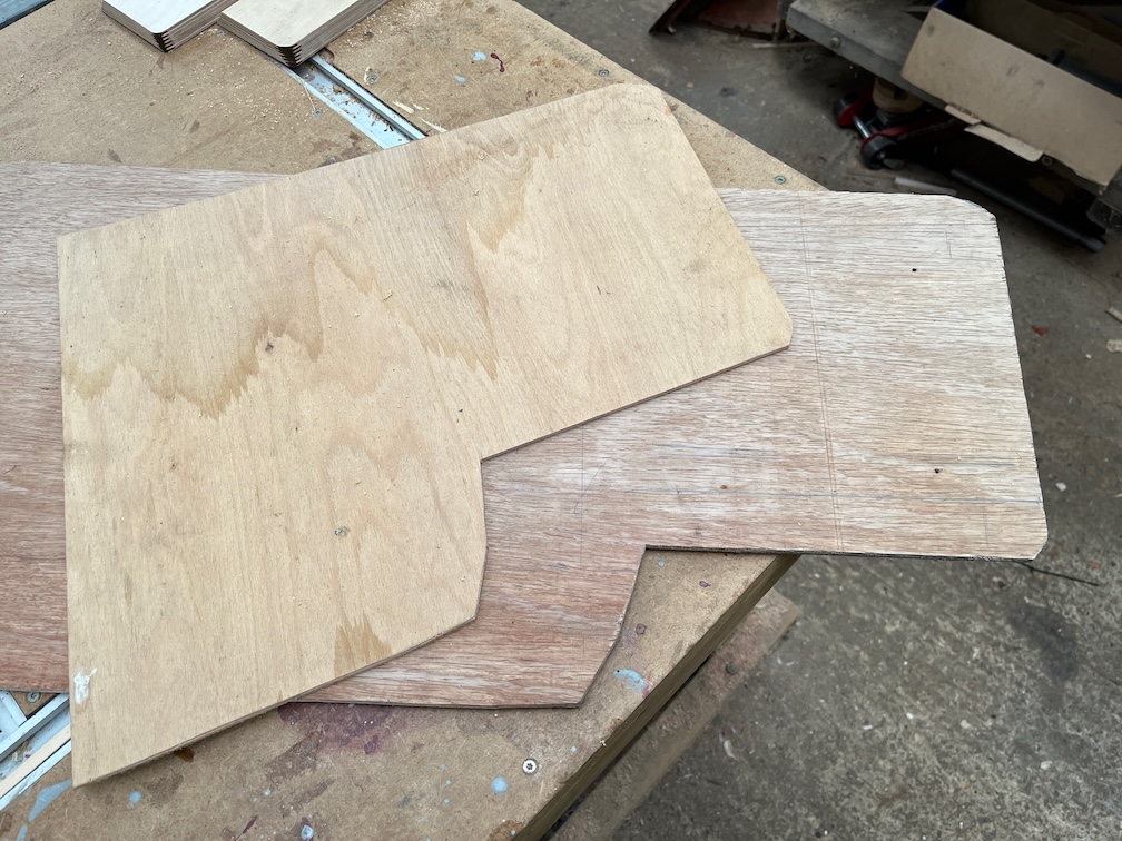
To prevent more cutting that necessary I aligned the straight front edge of the paper template with the edge of the workpiece.

The next task is to cut the rebates as doing this now whilst the block is still large and rectangular will prevent mishaps trying to do this later on when it is not.

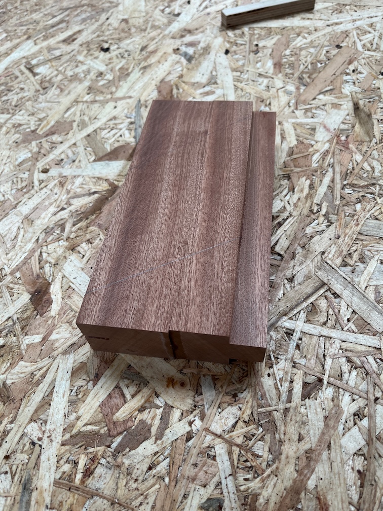
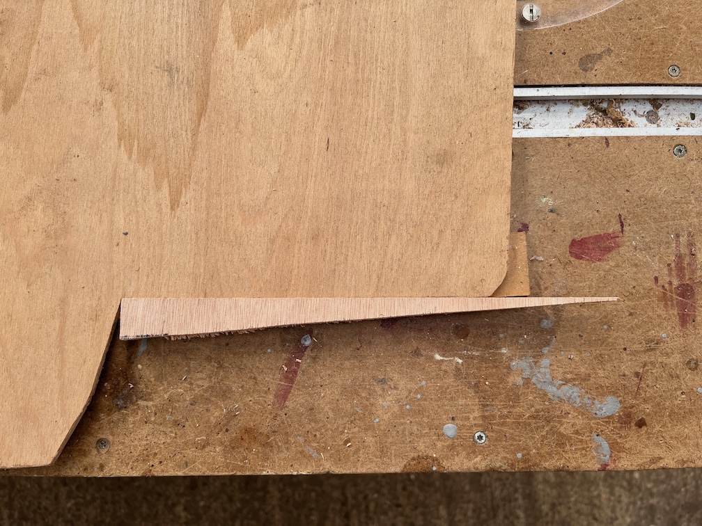
Four passes on the table saw and that is done.

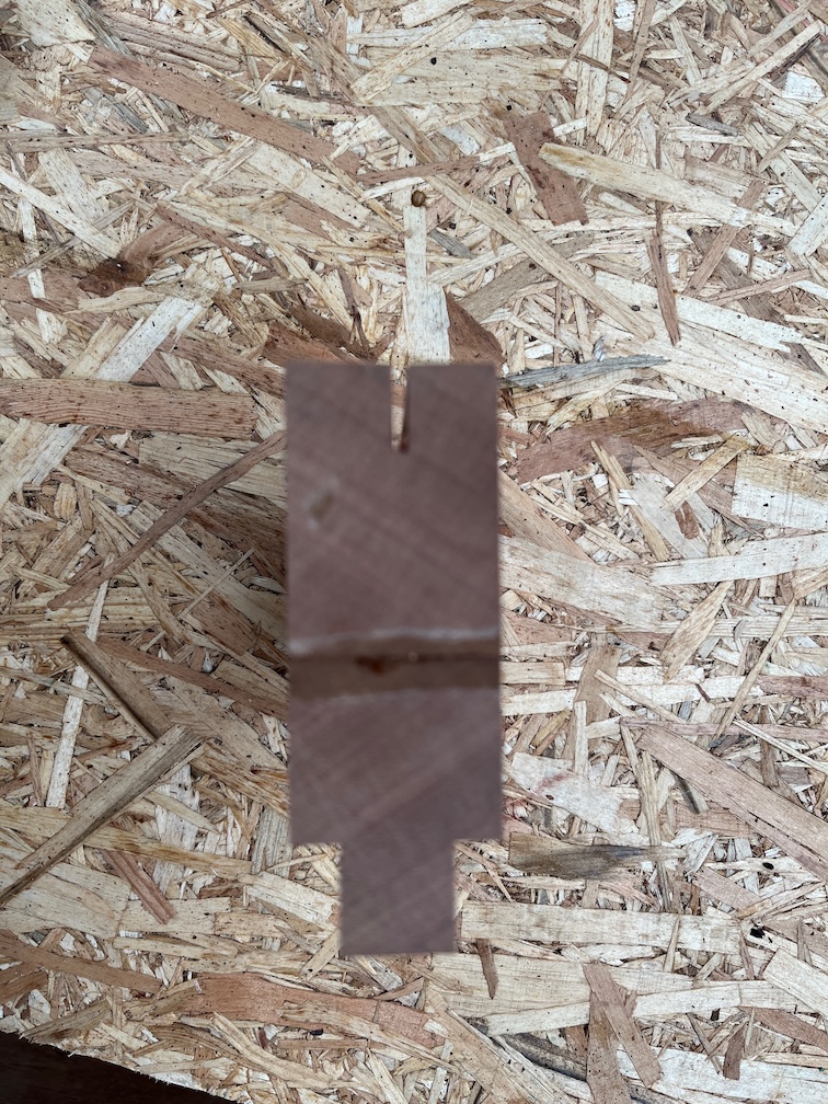
Mind you, I messed this up and made a cut in the wrong place for the first cut. Still, this will be minimal once the piece has been shaped and any errant slot remaining will be filled with thickened epoxy.

Time for a cup of tea.

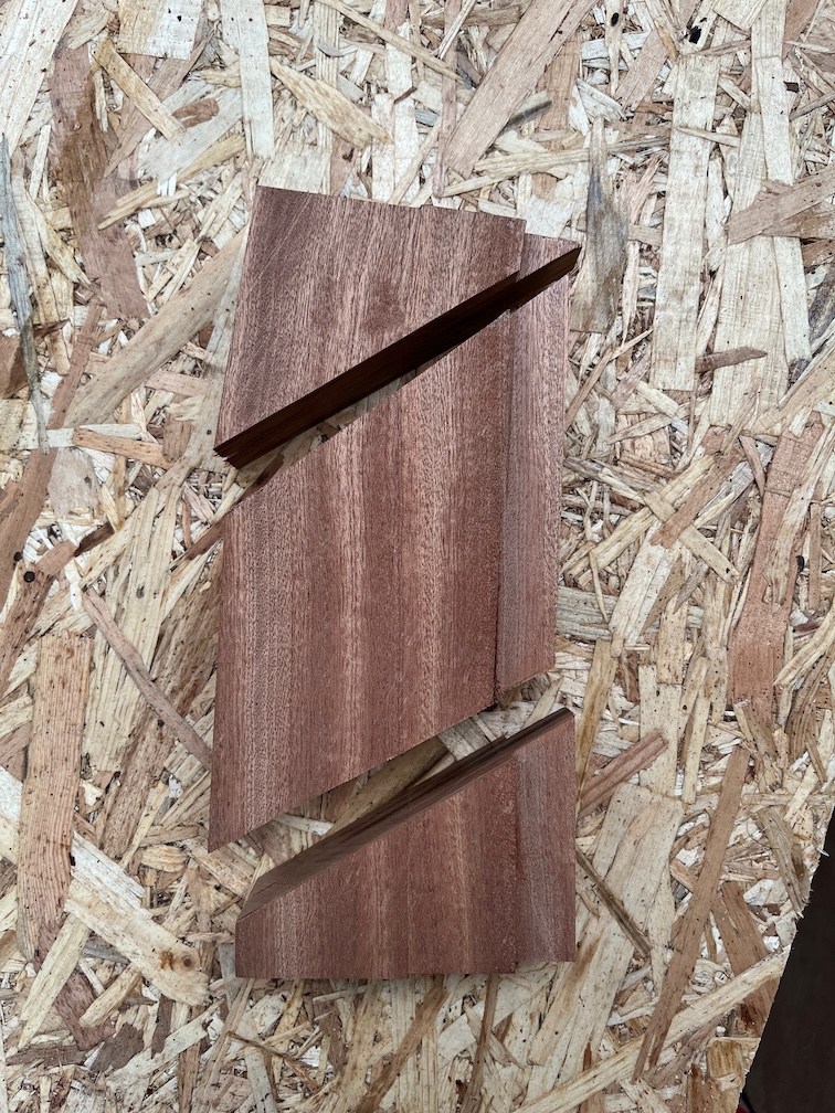
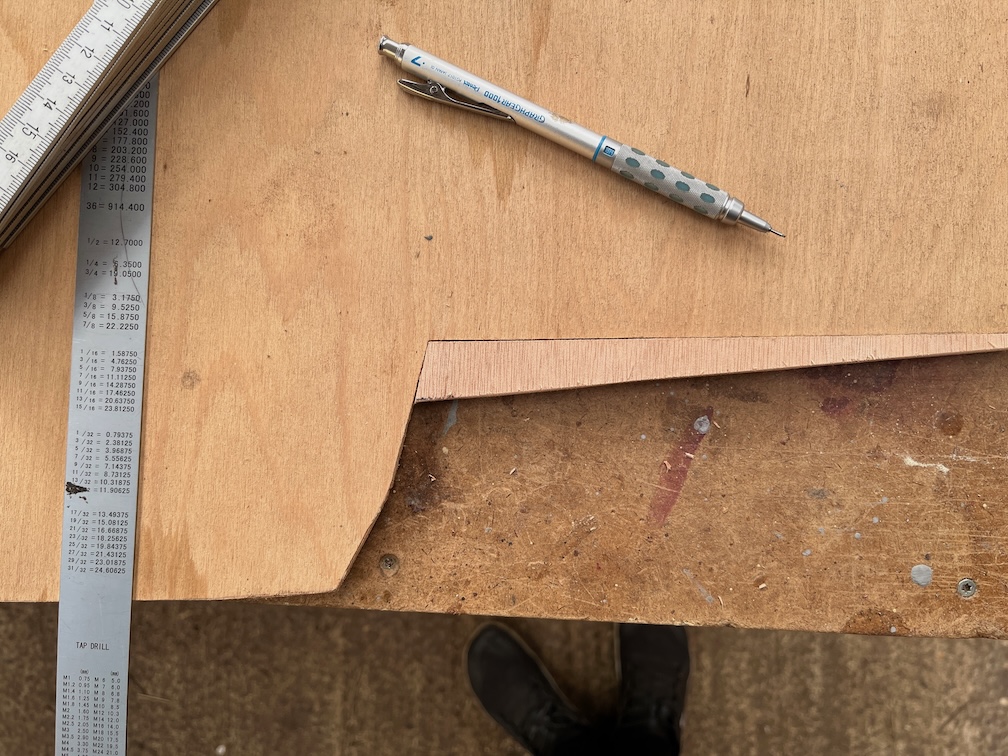
First the two easy cuts made on the mitre saw.

Then a straight cut at the back to get closer to the line made on the bandsaw (carefully).

Then the excess was sanded away using an oscillating sander. So far, so good.

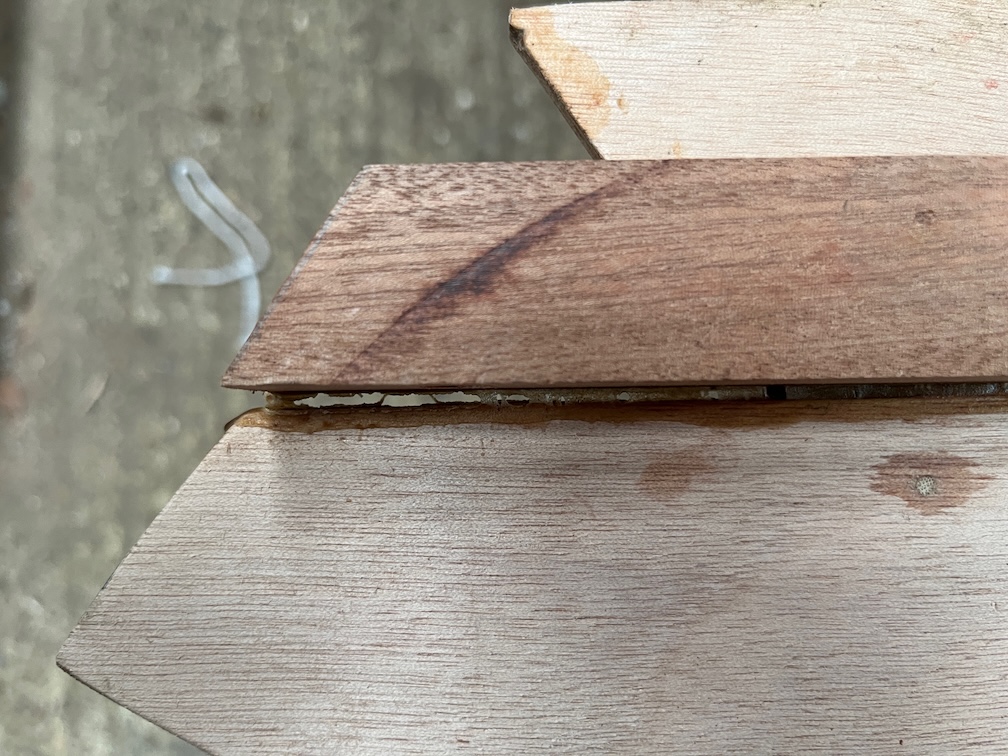
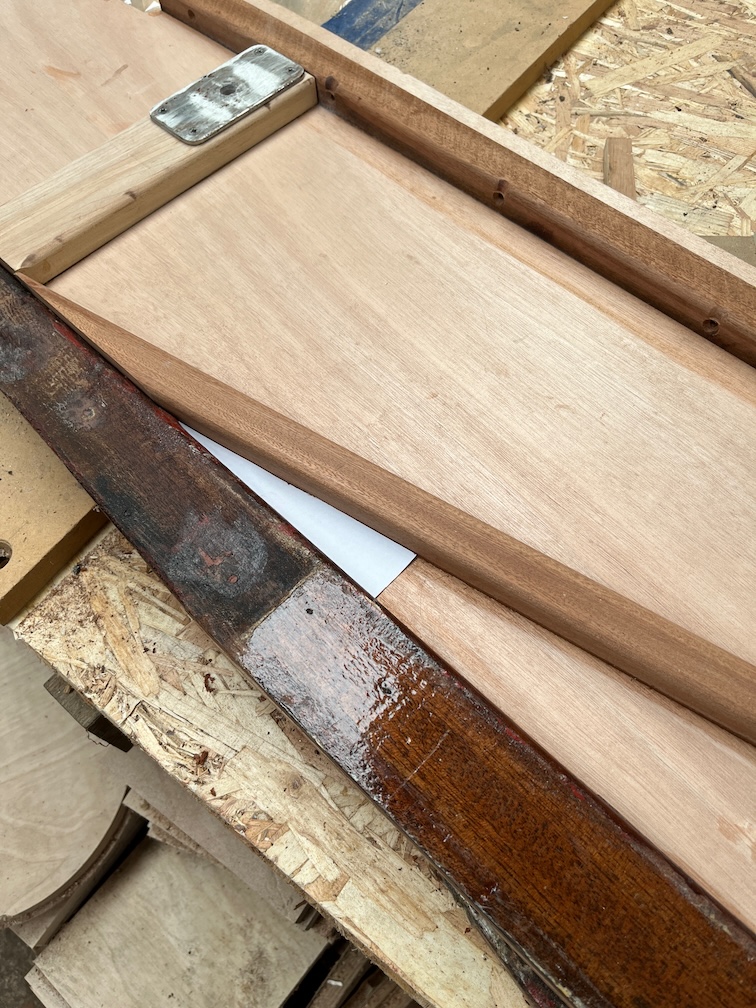
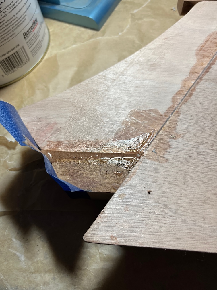
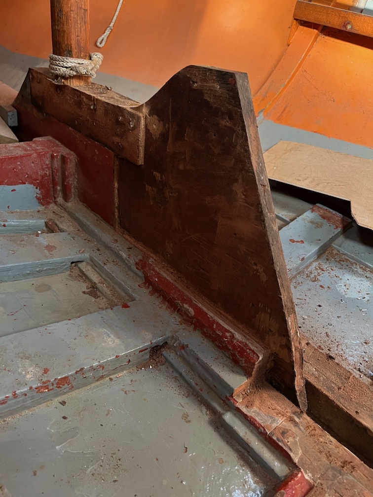
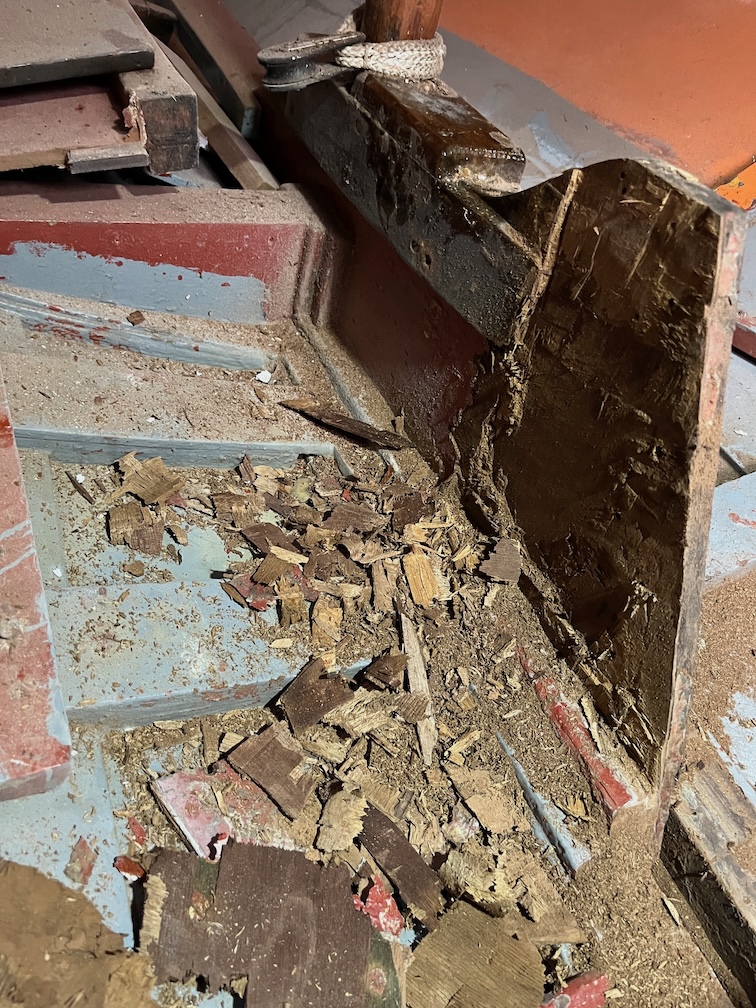
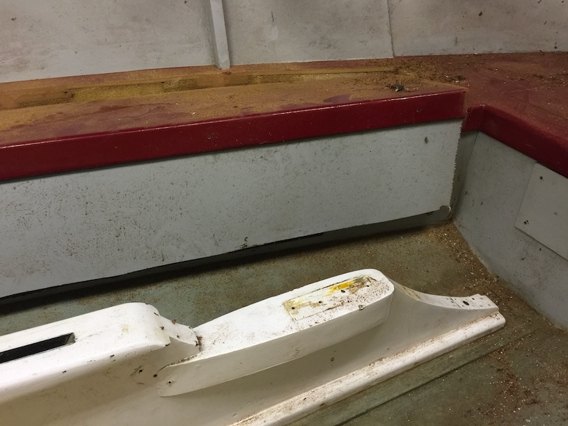
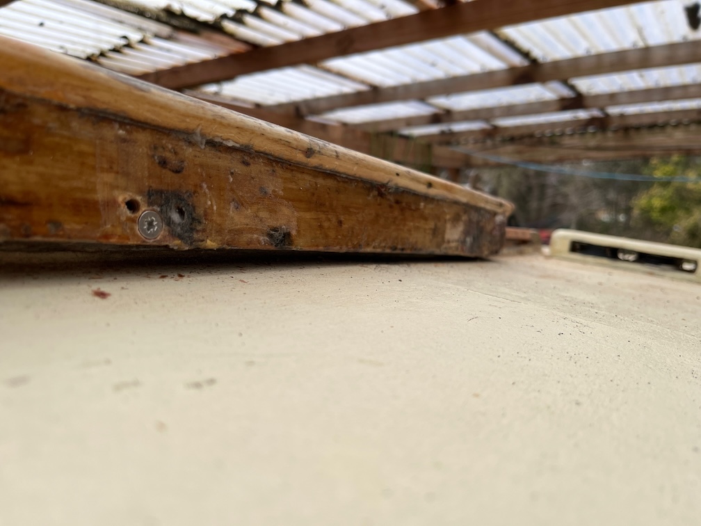
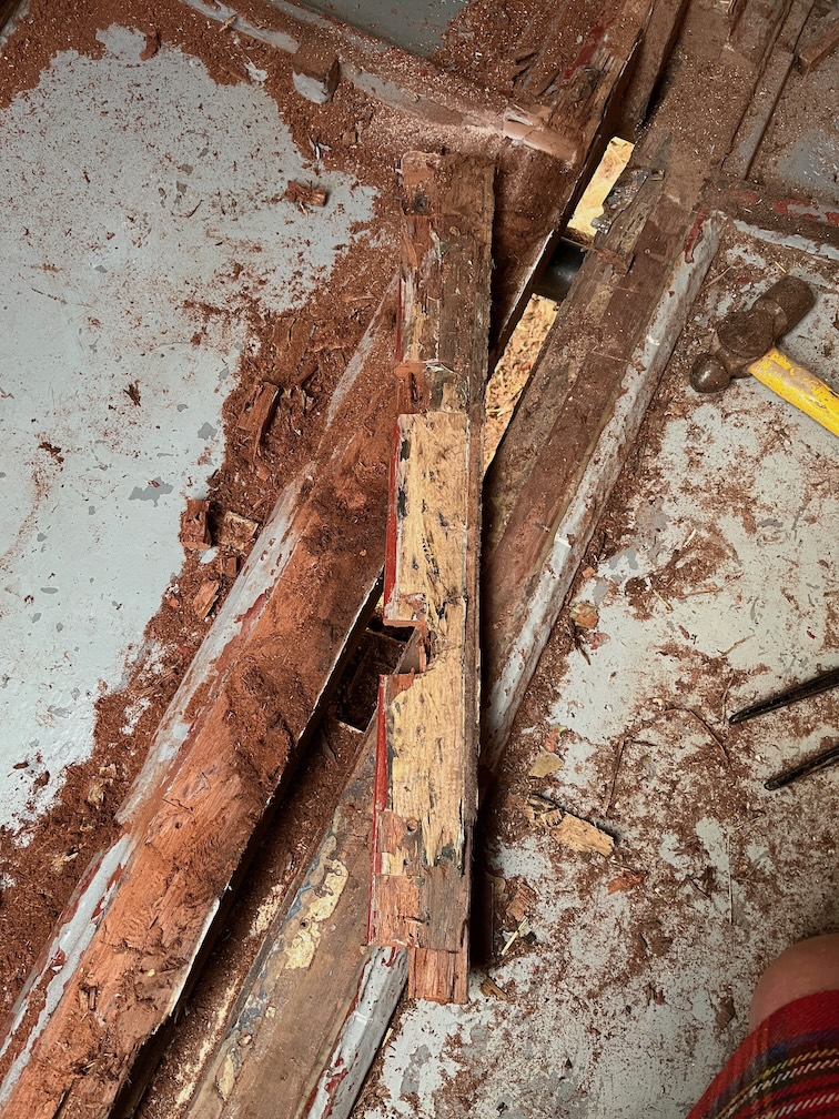
Not too bad for a first approximation. The front and sides are pretty much an exact fit, but the back has missed, fortunately on the plus side, not the minus.

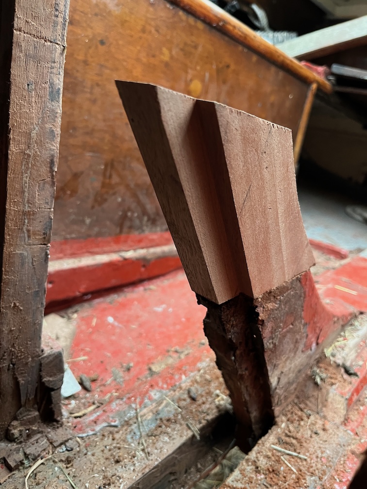
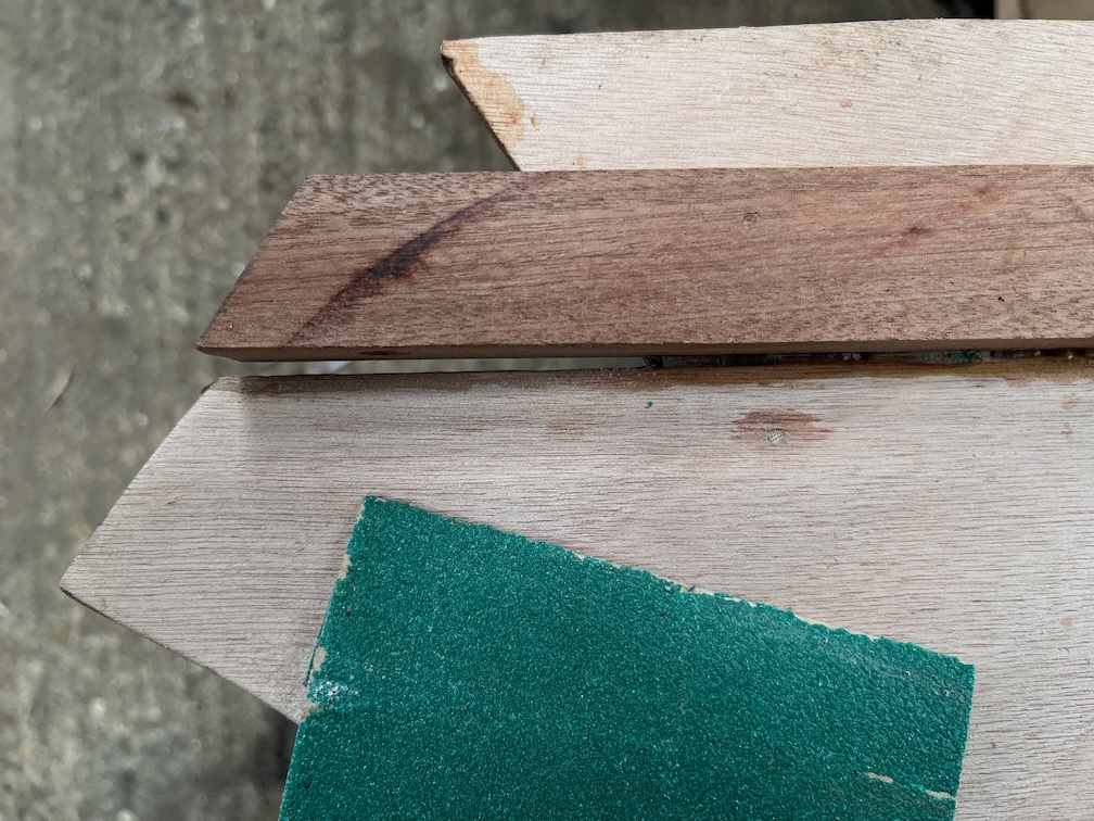
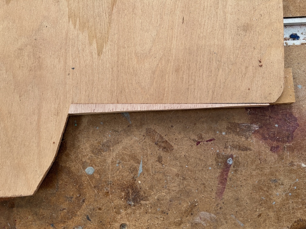
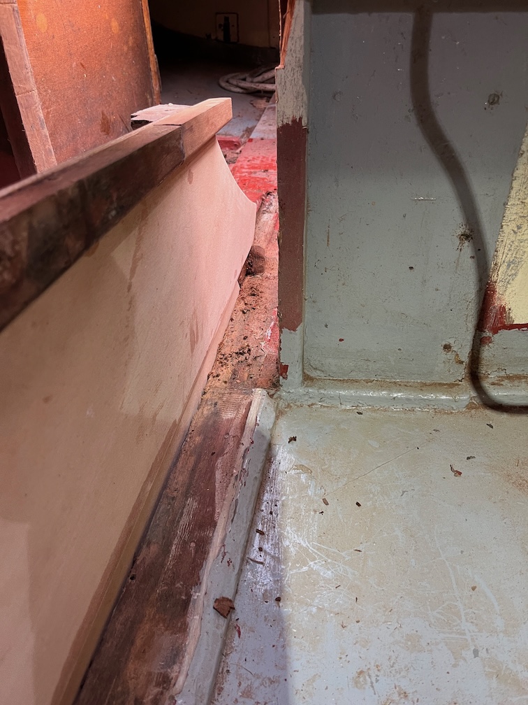
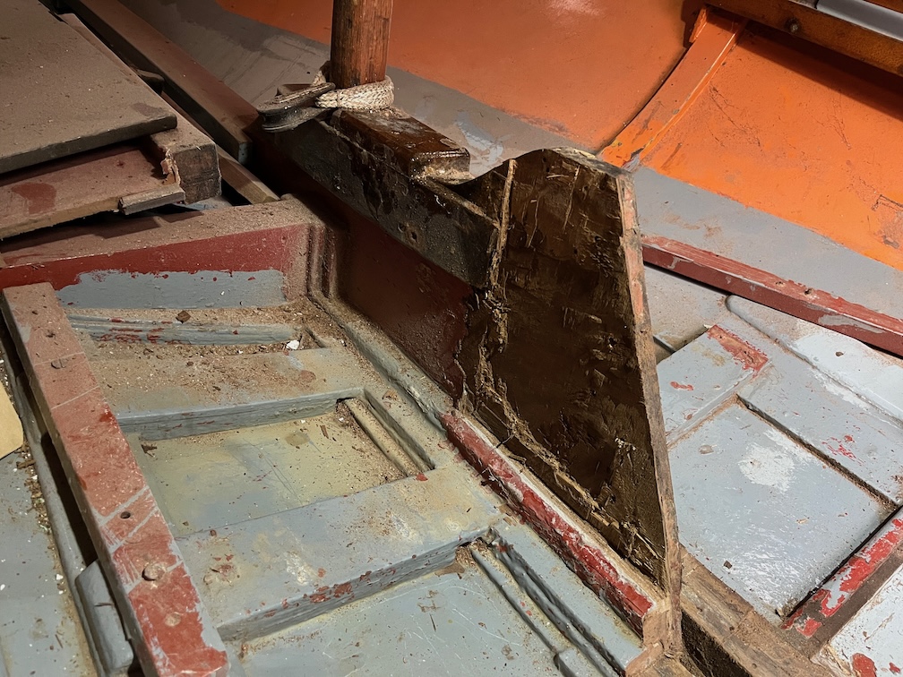
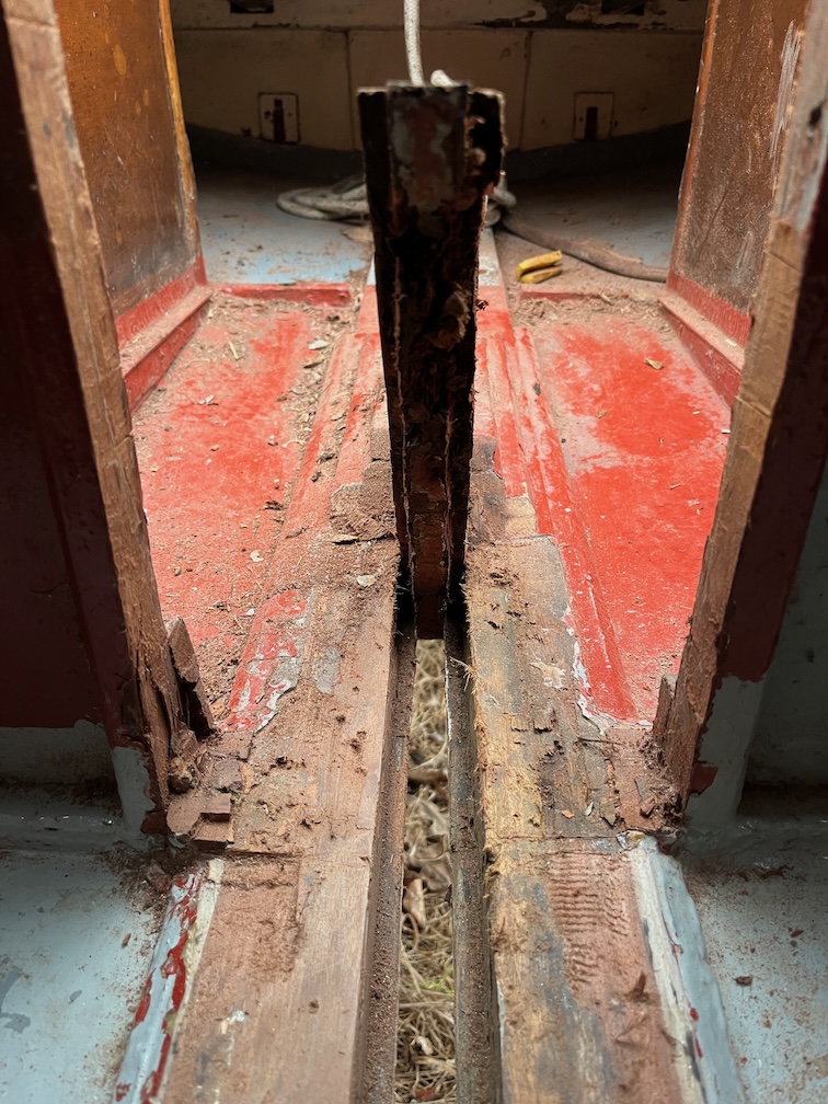
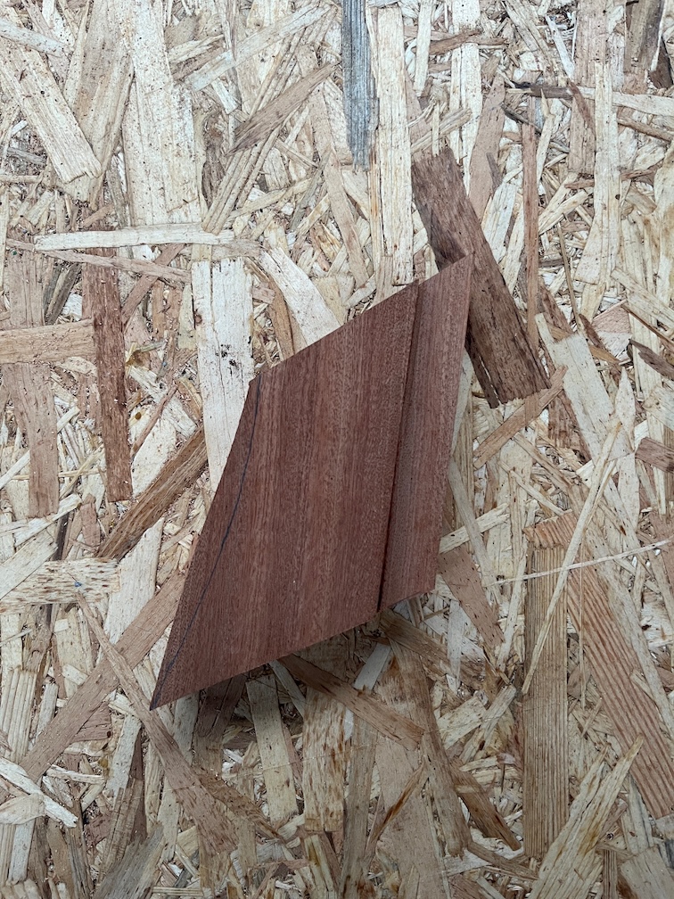
Here’s an inside view and the mismatch at the back is slightly more clear in this photo.

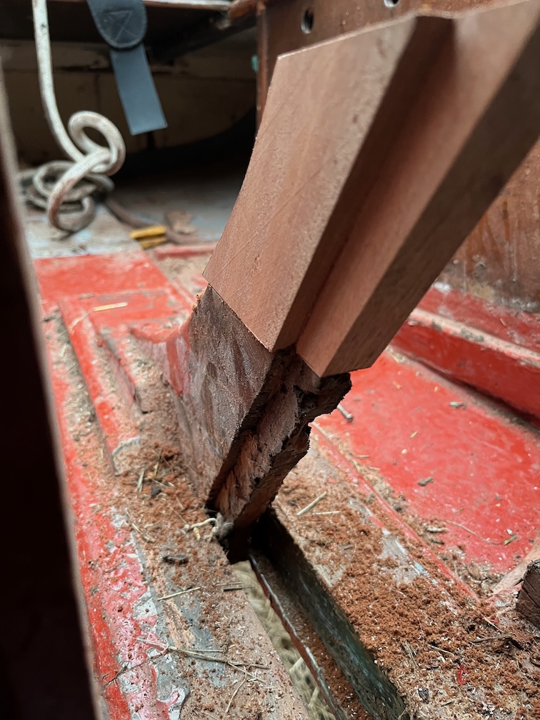
And this from the other side.

Time for a cup of tea.

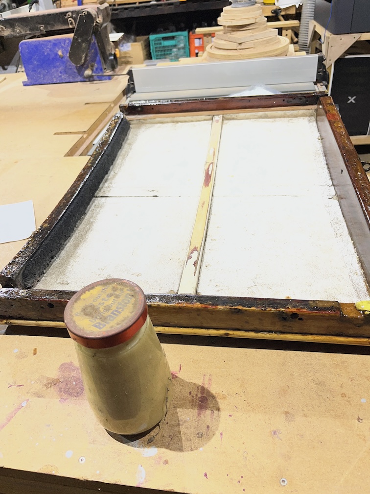
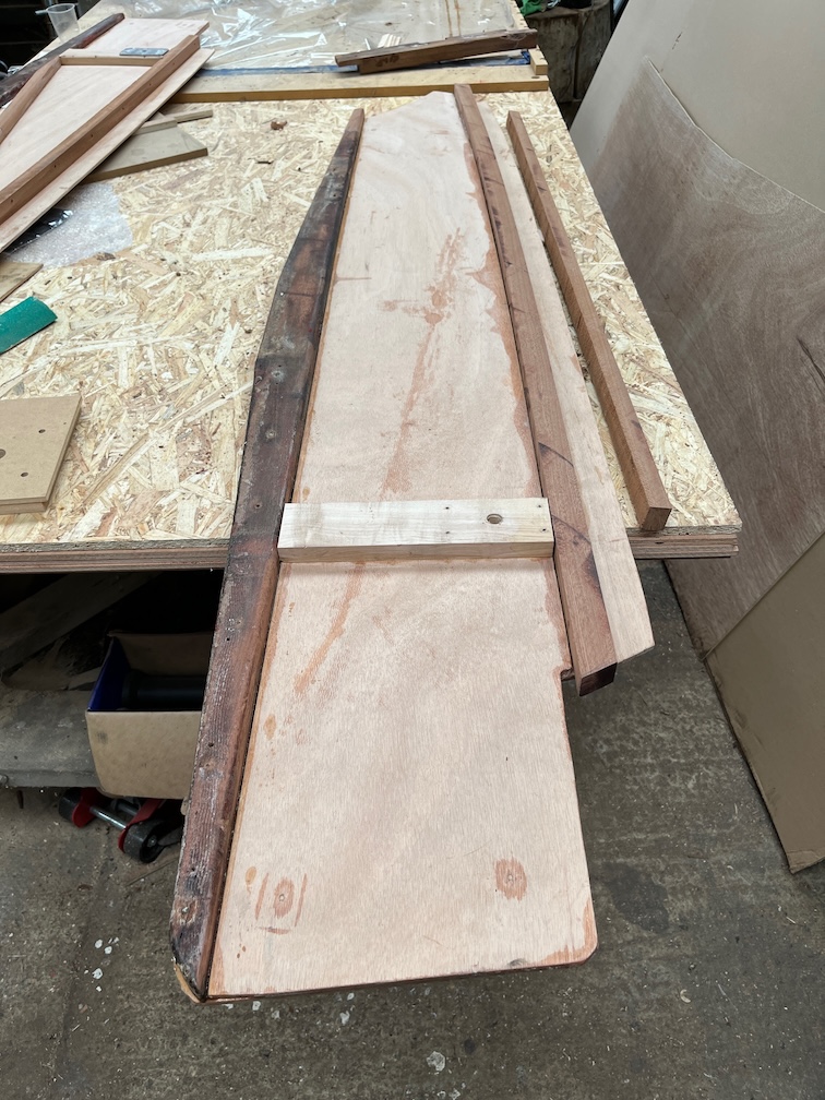
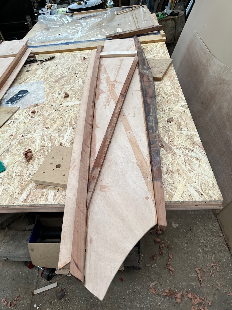
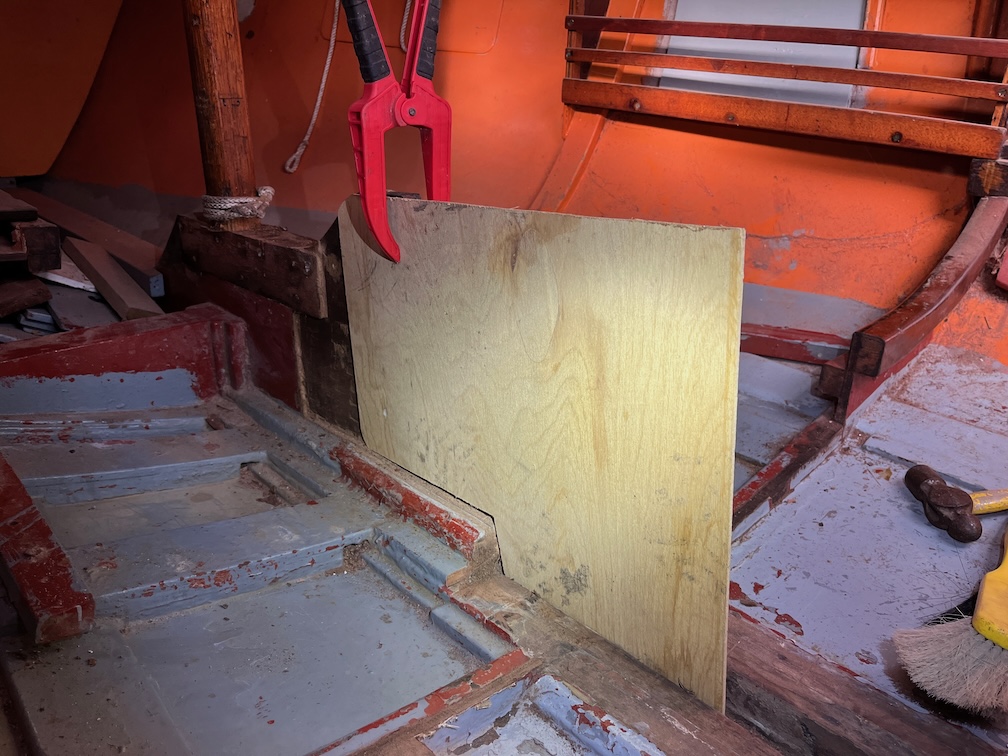
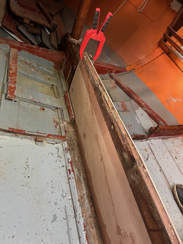
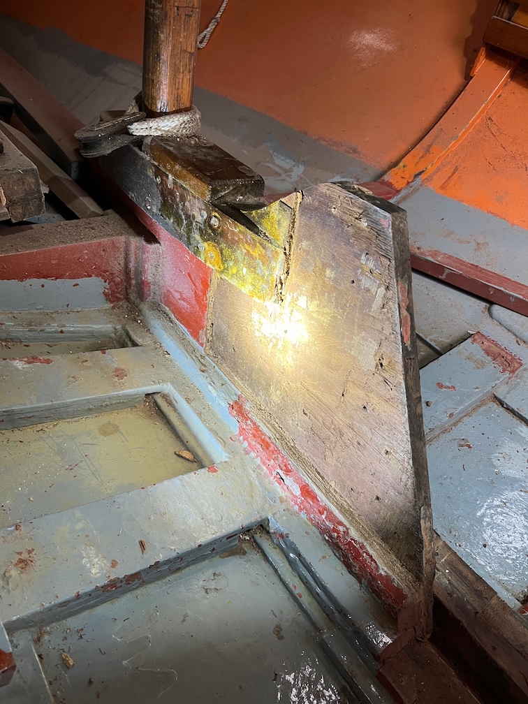
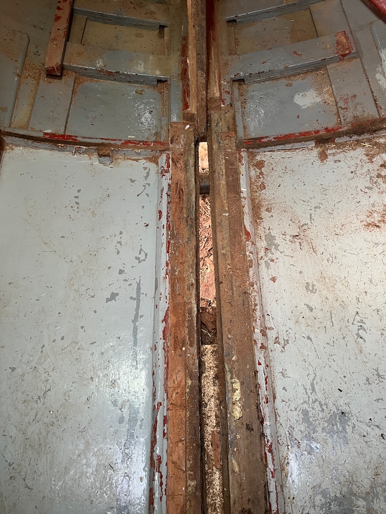
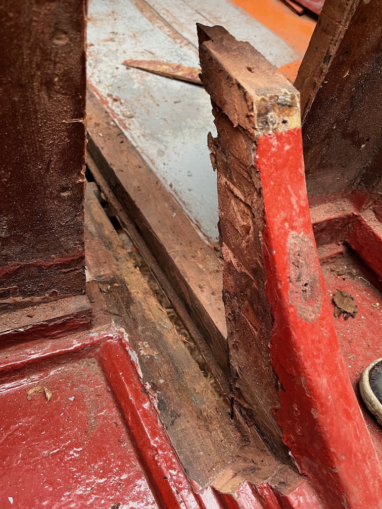
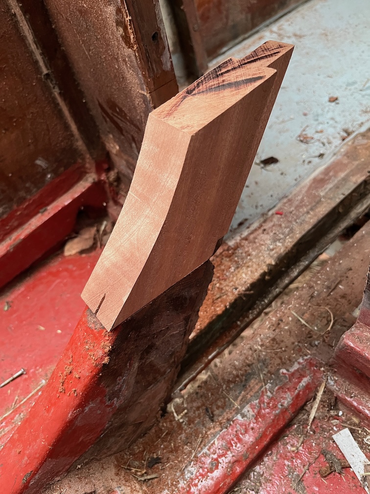
The next task is to put in the case side template and see how that fits with the new top.

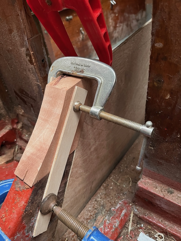
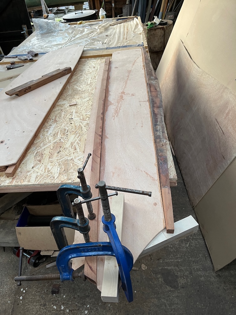
The template was put into the keel, clamped to the top and two thin battens clamped either side of the aft block spanning the old and the new as you can see above. These were to keep the new piece in position and upright as much as possible.

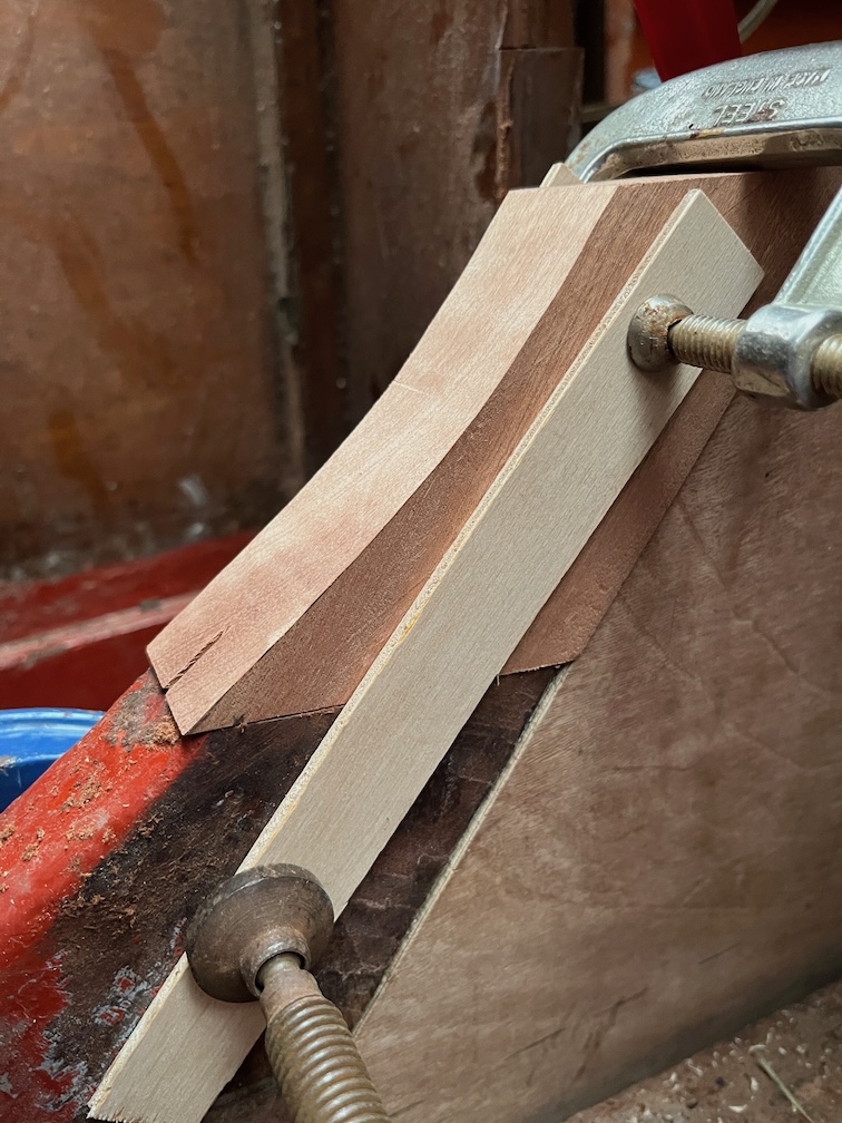
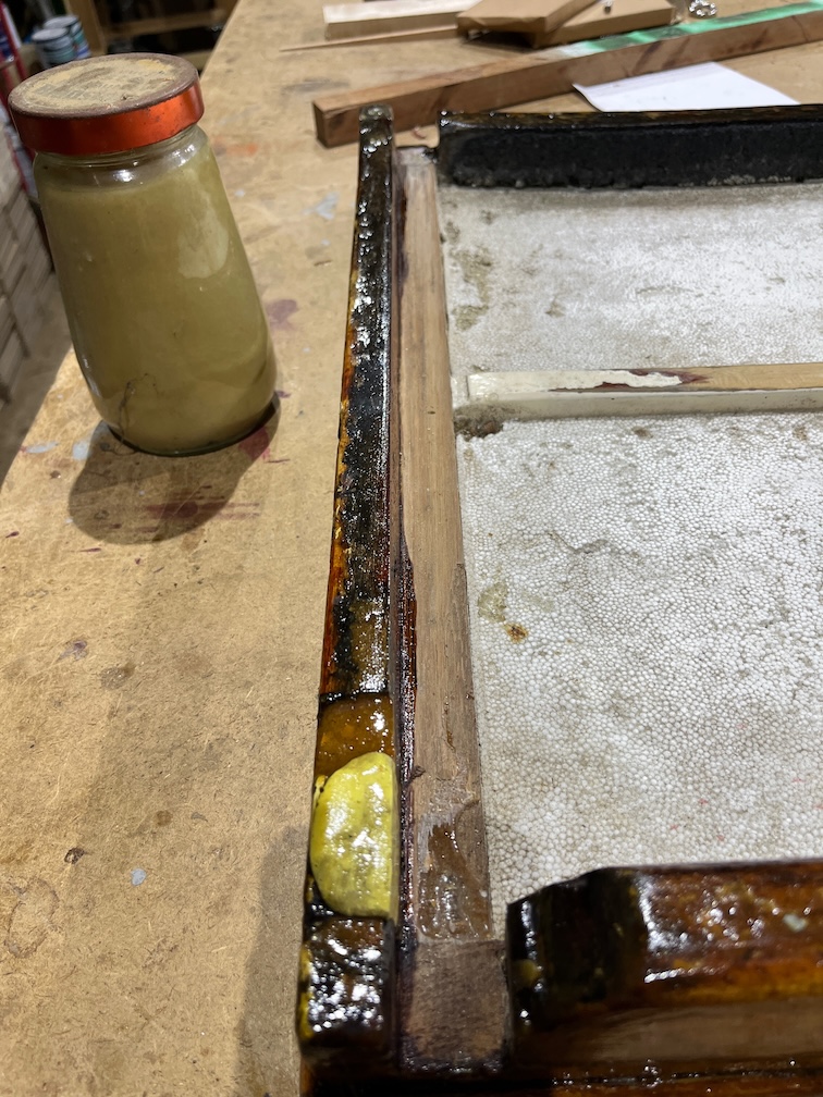
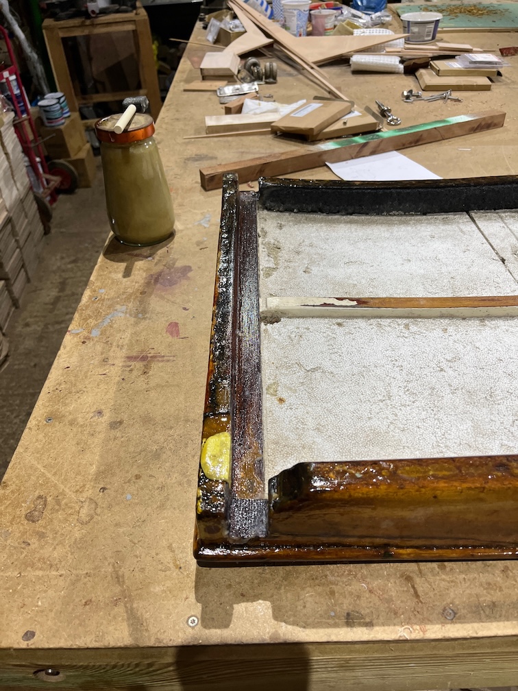
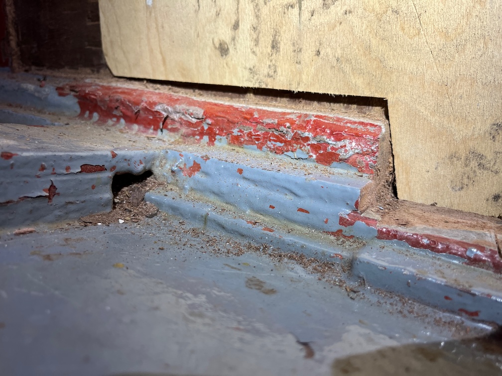
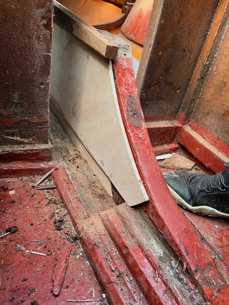
Looking at the new piece now you can see that the bottom of the curve on the new section isn’t that far off.

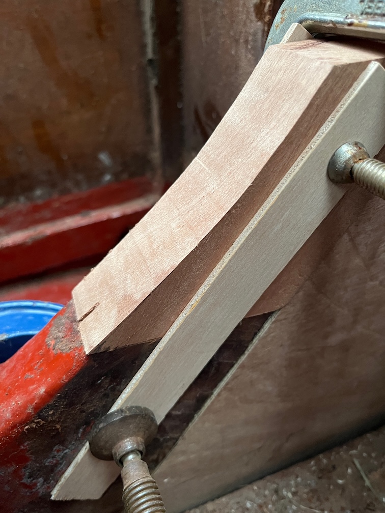
So, I carefully sanded a bit more off until it was a pretty good match.

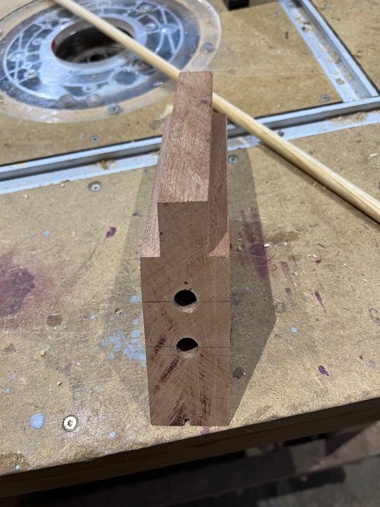
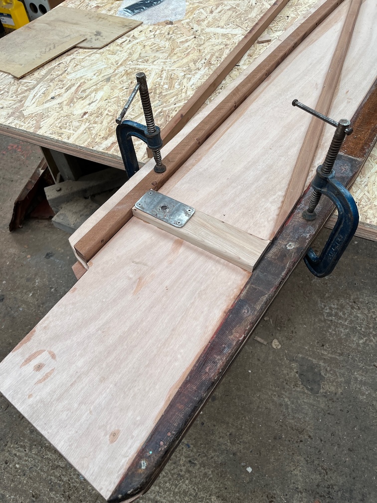
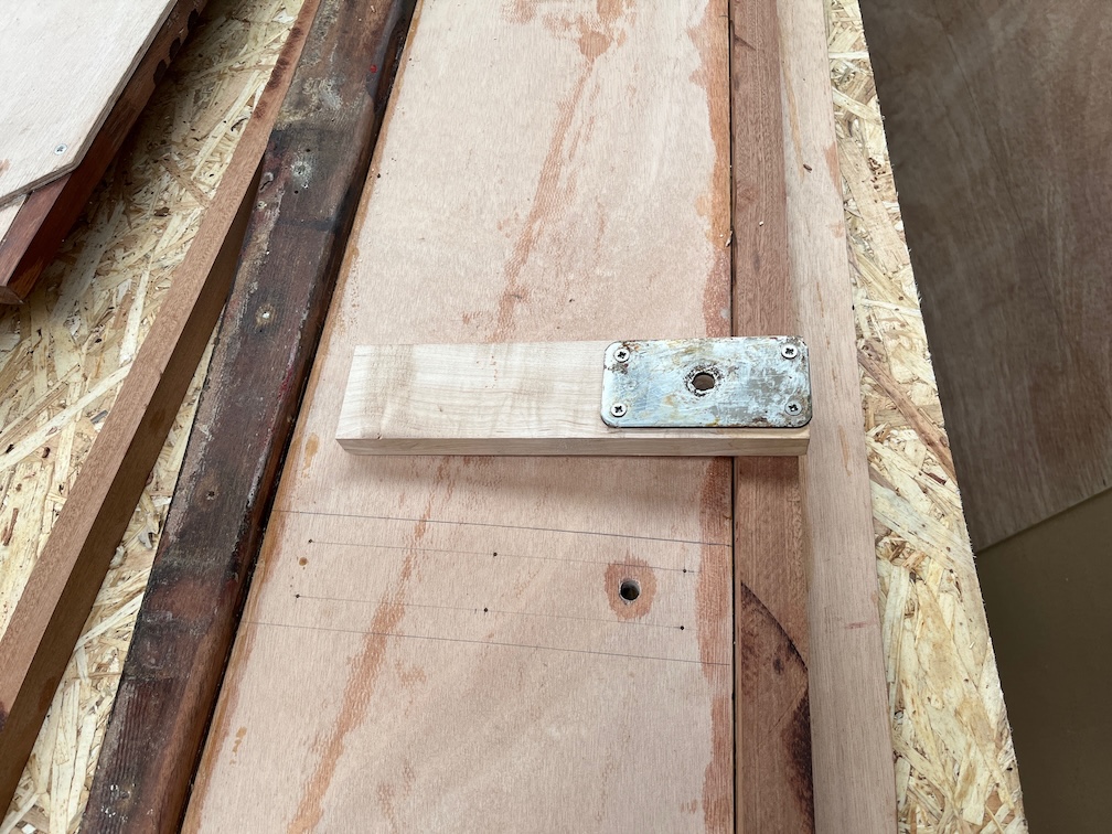
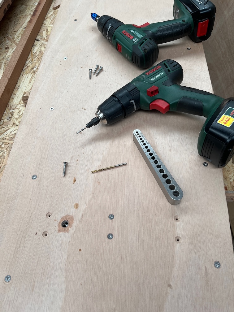
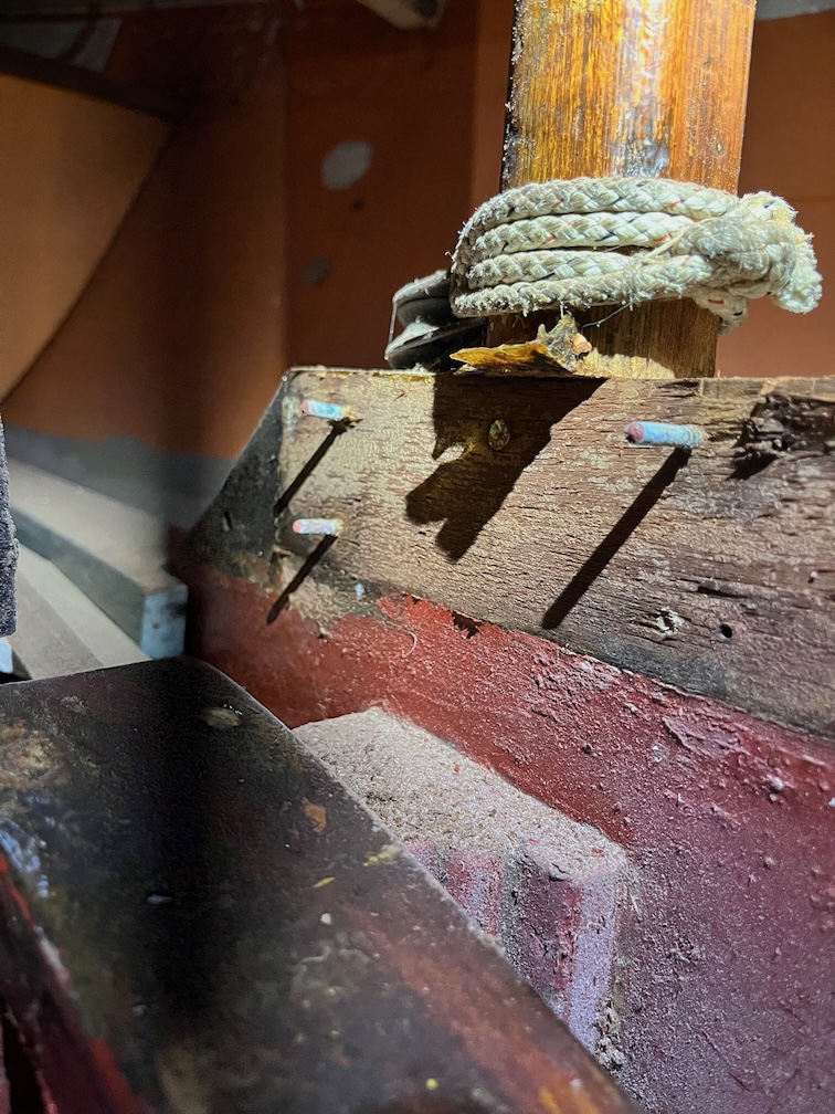
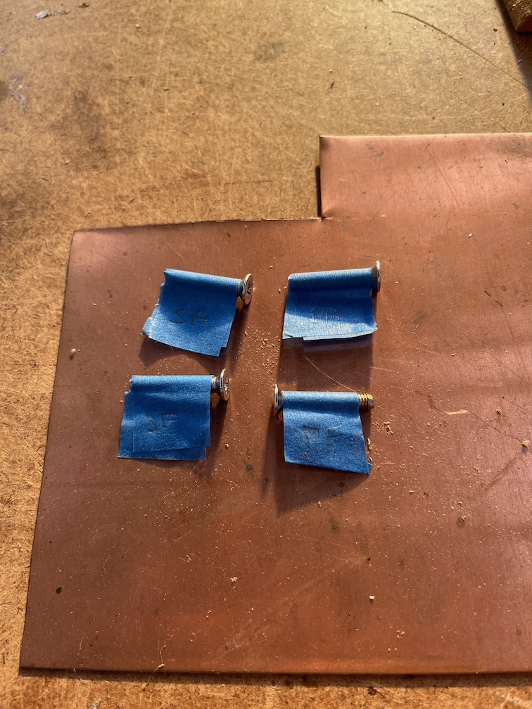
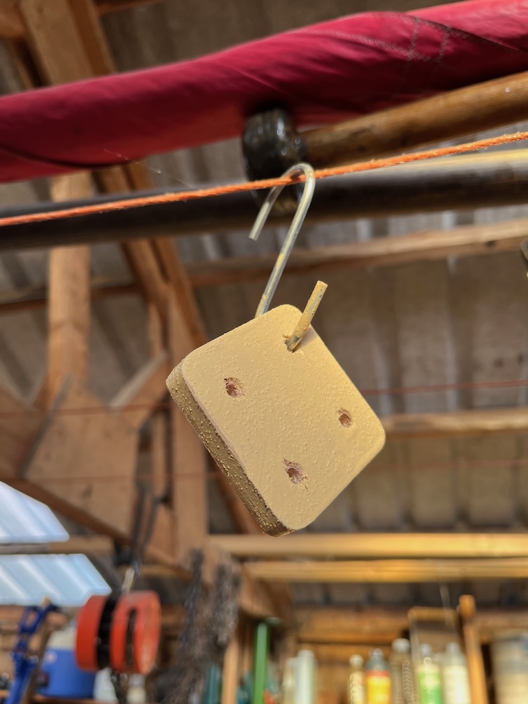
Using a self-centering dowel drilling jig I drilled two 10 mm holes through the new top, both being perpendicular to the bottom.

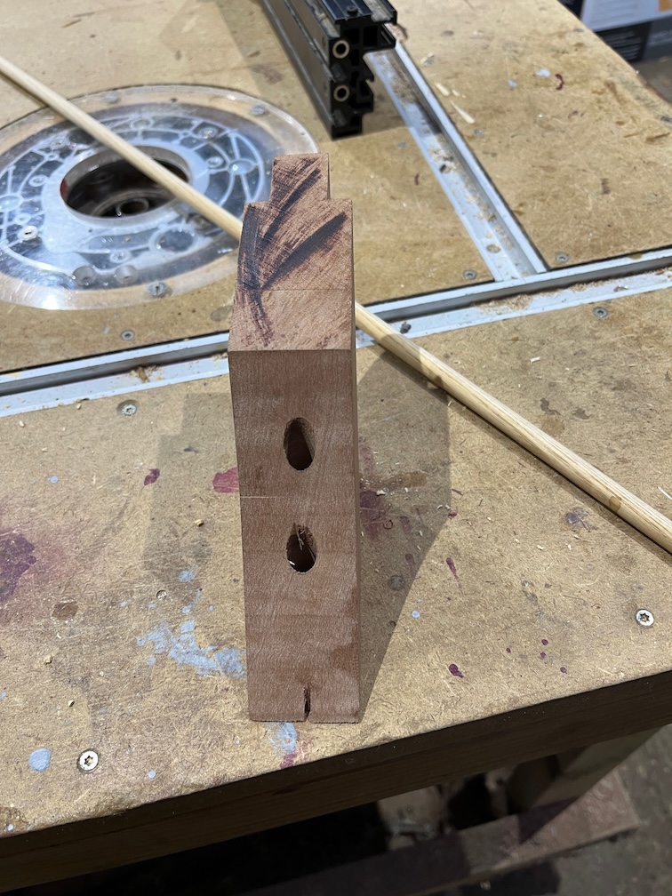
I chose to drill them completely through the block rather than attempt to drill matching holes in the old section by guesswork. This way I can clamp the top piece in place and drill down through the holes and get a perfect fit.

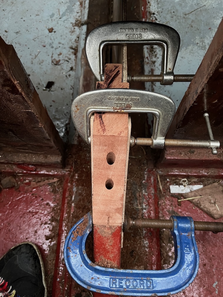
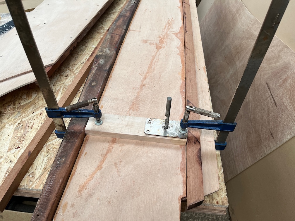
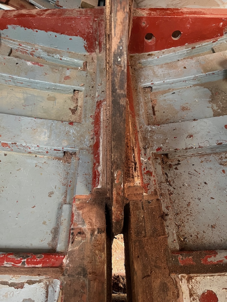
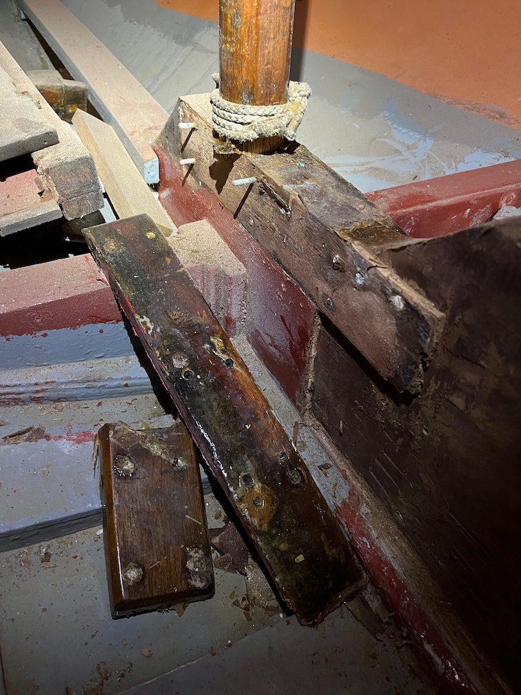
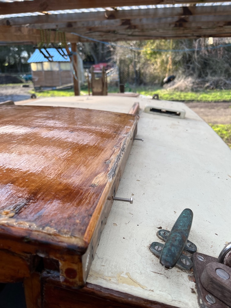
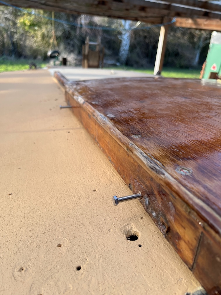
The block clamped in place…

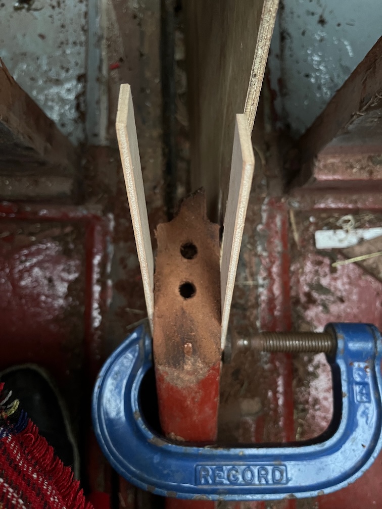
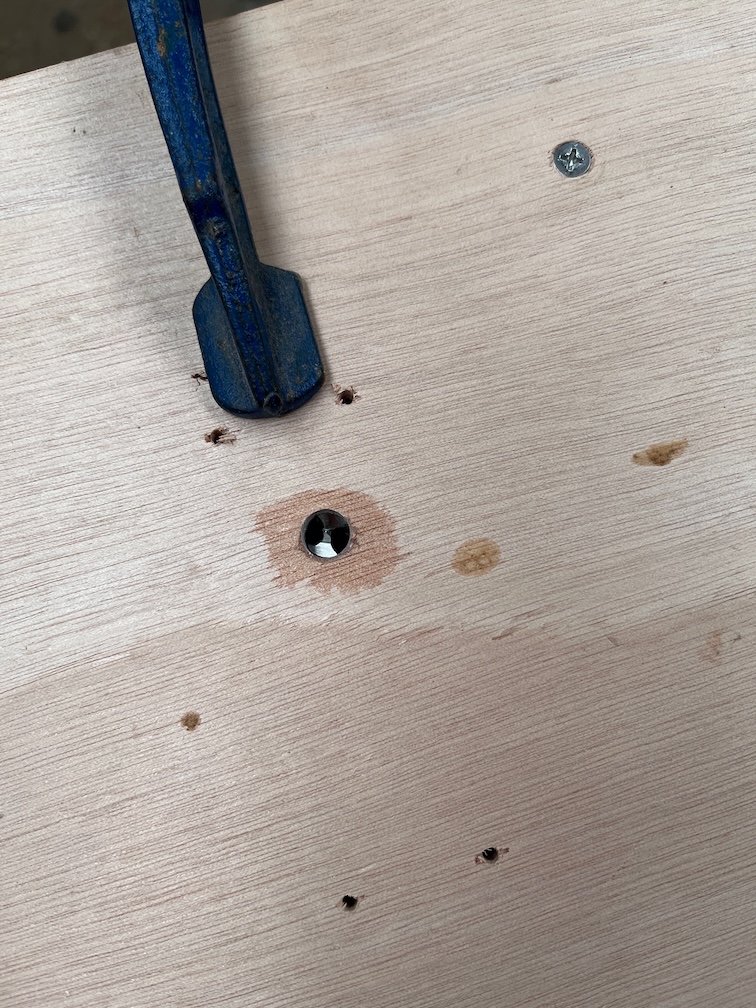
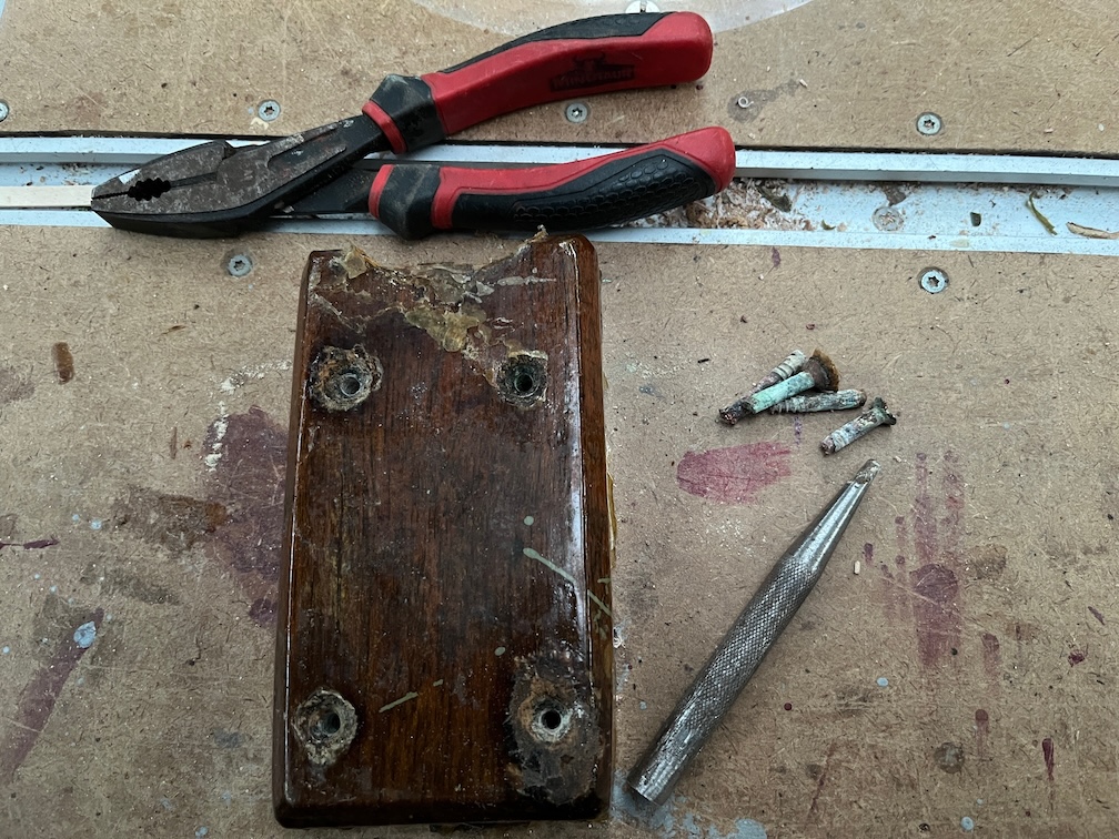
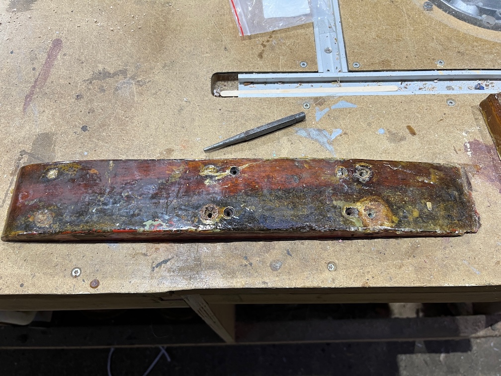
…and the resulting holes in the bottom section.

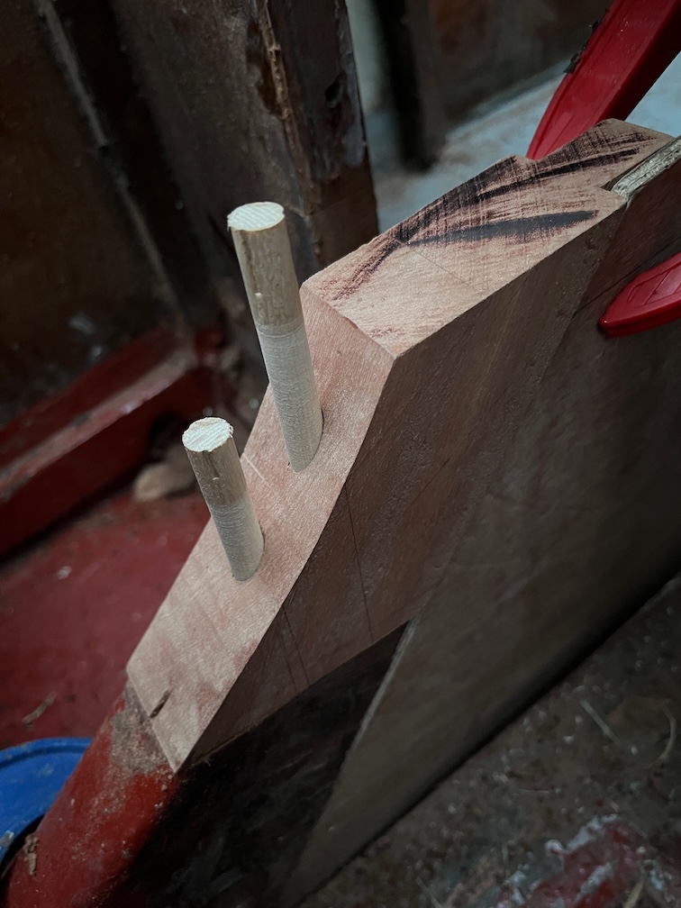
I used two pieces of an medieval style arrow shaft, made from Ash, which was 10 mm in diameter and sanded it down a little to make it a loose fit. I put each piece into a cordless drill, wrapped coarse sandpaper around the shaft and spun the shaft until the desired fit was obtained.

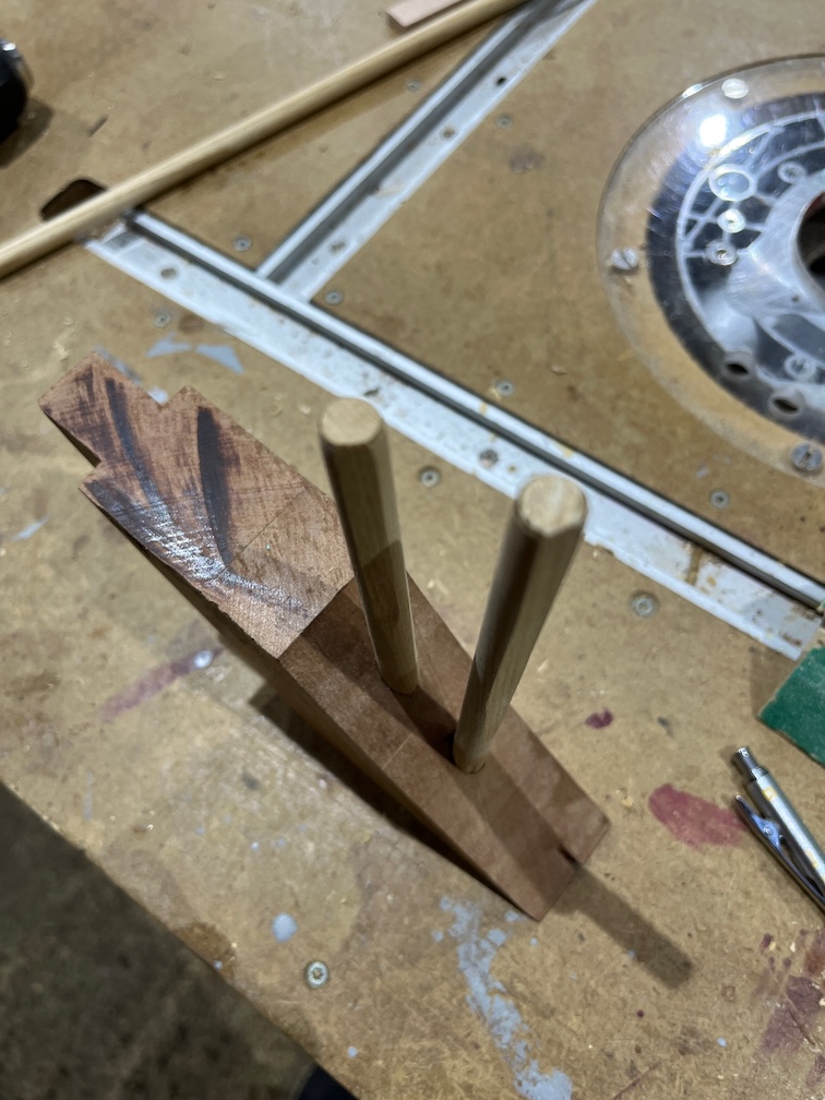
Finally for this part I sanded a flat section on each shaft. Without this the dowels will not seat properly as the pressure from the air and glue being forced into the hole pushes the dowel out again. This is the reason that the dowels you buy from a hardware store are not round but ridged all round.

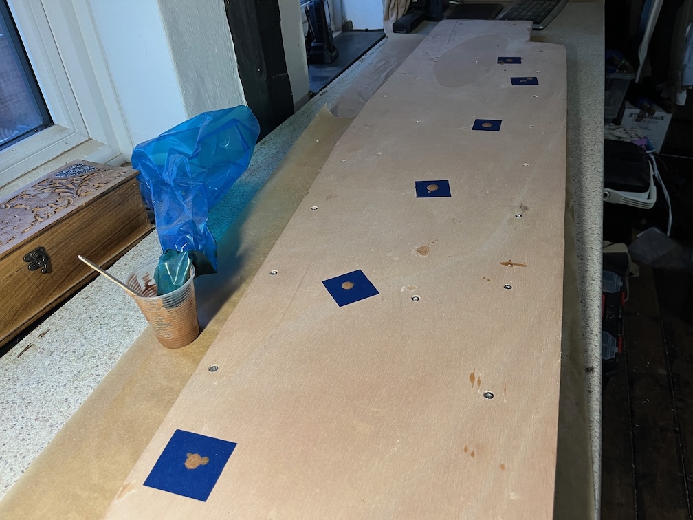
The holes in the bottom section were filled with Clear Penetrating Epoxy Sealer and I was gratified to note that the CPES did not soak in much, indicating that the wood through which the holes were bored were not porous. I did coat the top of the wood and that did soak in but that is endgrain and I would have been perturbed if it had not on any but the very densest woods, of which this is not. I also put CPES on a number of other areas in the boat that have been waiting until I had enough to make it worth mixing up a batch.

That concluded the outside work for the day, inside I put the third coat of varnish on the galley stove boards.

Not a bad day’s work. All small things but on the critical path. While I wait for the CPES to dry, three or four days in this temperature, I’ll finish off the case sides which need to be trimmed and a bead of sealant put all around the outside corners where water could collect.

Time for a cup of tea.

2026-02-06 – More of the Same

Not surprisingly, the tasks for today were pretty much the same as yesterday. An early start to get the first layer of epoxy on the second case side and so on and so forth. Didn’t bother with photos for the second side, it’s all the same as the first.

The new ship’s battery arrived this morning, which was a bit of a surprise since it was due to arrive next Tuesday, not that this is a problem, just that I wasn’t expecting it today.

Here is the new battery on the bridge deck instead of the old one. I can tell that it makes a difference since when you turn on the cabin light, the battery voltage does not change whereas with the old battery, the voltage would drop by half a volt or so. The cabin light is a 5W bulb meaning that the bulb draws around 416 mA from a 12V supply and a battery in good condition should not show an appreciable voltage drop.

However, I might have made a slight mistake with the measurements.

I measured the gap as 320 mm as you can see here, although looking at the photo now, the real gap will be 340 mm since the inboard end of the battery will be sitting on the lower runner so that it is level (ish).

But, and this is a big but, I forgot that there will be a centerplate case support here that will reduce the width.

Holding the support in place I can see that I just have 310 mm, which is the width of the battery, so the battery will go through the gap…

…but only is I take the door off !

So, a mistake, yes, but not a bad one. I mean, how often will I be taking the battery in and out? Maybe twice a season, once at either end, but probably not even that.

The door had to come off

“All right,” said Fred, “Have to take the door off
Need more space to shift the so-and-so.”
Had bad twinges taking off the hinges
And it got us nowhere
And so, we had a cuppa tea

The door came off without too much bother, only one screw caused a problem as it sheared off in the jamb. Annoying since this means that I will need to move the hinge so that the new screw doesn’t try to screw down through the old one.

Door with all the fittings removed.

The fittings and fixings. All brass except two stainless screws. All the fixings bar the stainless ones went in the bin and I’ll replace them with A2 stainless. I did think of replacing the hinges and latch with stainless equivalents, but they are still good enough or will be after a bit of cleaning.

I’ll not replace the eye straps as these were for the bungee that restrained the Camping Gaz bottle when using the radiant heater and we don’t have that anymore, so the eye straps are redundant.

Anther small task was to run the power cable for the compass light. This would have been a total pain were it not for the fact that the centerplate case has been removed allowing me to lie on my back with my head under the bridge deck from whence I could hammer in the small cable clips to hold the cable.

As before, I used small bronze panel pins instead of the steel nails that come with the clips.

And this is the result. The round cable is the power cable to the starboard navigation light and the black and red cable is the one for the compass light. There are a lot of other unused clips in there. There are two possibilities. The first is that there used to be another cable possibly for a quarter berth light and the second is that the cable was put up by feel from the cabin and these are the clips that failed that exercise.

I put a lever connector on the end but left it dangling. This will be connected to the cable from the compass and I’ll have to find a way to stick it to the underside of the bridge deck but still accessible so that the compass may be removed from time to time. Not sure how to do that yet.

I used a carpet offcut over the keel to make things a little more comfortable.

Talking of the compass, I was not happy with the way in which the LED wires were dangling out of the bottom of the housing, they are thin and not strong, so I took the compass apart and extended the wires using two lever clips. The connector and the wires were held down with hot glue.

The new wires still hang out of the bottom of the housing, but they are longer and more robust.

Well, I think that is a good place to stop for the evening.

Time for a cup of tea.

2026-02-05 – Adding the Glass Mat

The final stage of the case sides before fitting is to sheathe the inside of the case. Since there are going to be three epoxy applications per side and the second and third layers need to be applied whilst the prior layer is still chemically active, this is going to be an all day event, sort of. It will be apply the next layer and wait. Repeat three times.

I set everything up yesterday evening and first thing this morning I started.

The first layer is unthickened epoxy spread onto the inner side. This is allowed to soak into the wood for a while before the next layer is applied.

There is a slight wrinkle to this layer in that the aft end has a part that is not inside the case but goes alongside the aft block. This part has only one coat of epoxy and needs peel ply added to remove the amine blush once the epoxy has cured.

Now we wait for this layer to start curing. The stage we are looking for is when the epoxy gets to be about as tacky as Sellotape.

Time for a cup of tea.

Three hours latere the next stage is done.

The cramps hanging down over the edge of the case side are there to ensure that the glass mat drapes over the curved edge of the plywood without any lifting. I have done this to ensure that the edge of the glass mat will be under the bottom edge of the side when installed. This means that when the centerplate is lifted up, there will be no edge of glass mat to catch on the plate and eventually tear off. This way there is just a smooth curve and no edge.

I hope.

Time for a cup of tea.

Finally, for the coating of this side at least, the third layer.

This layer has graphite added to the epoxy, 10% by weight, to form a more lubricating surface. The result is a black epoxy layer which looks really nice to my eyes. Shame it is on the inside and will not be seen when the case is assembled.

I will give it a few moments to level out and then I will wave a hot air gun over the surface to pop any bubbles that remain after the mixing.

This has to be left for 24 hours or so to achieve full strength and then I will take it down to the workshop and trim the edges of the glass mat. After that it will be the turn of the other side.

Time for a cup of tea.

2026-02-02 – More Small Tasks

Just a few small tasks today, starting with applying the third coat of varnish to the hatch runners on Shoal Waters.

It is also time to apply some slippery gunk to the hatch itself. I made a jar of furniture wax a decade and a half ago consisting of beeswax, linseed oil and White Spirit for several projects I had back then. I made a lot more than I needed, but it has proved useful during the intervening years. I recently used it on two rope winding heads, on the teeth of the wooden gears.

Today I’ll use it on the htach.

This is the before photo, you can see that the wood is mostly untreated. It might have been treated with something originally, but years of sliding back and forth on the runners would have worn it off.

This is the after photo. I’ve applied two coats of the mixture. The white spirit acts like a solvent for the linseed oil and beeswax and penetrates the wood. The the spirit evaporates quite quickly and after that the oil slowly polymerises. The effect is to carry some of the beeswax into the wood leaving some on top of the wood.

The nice thing about this mix is that after a few days the surface of the wood is just covered with a thin layer of wax. If you get it on your hands or clothes, it is easily washed off.

The last task for today, I’m having a ‘rest’ day and not doing that much, is to cut the glass mat. I bought 2m of 1.27m wide 300g biaxial glass cloth and it needs to be cut in half.

Half of the mat covers the case side with plenty to spare, although I’ll probably need to cut it down to size a little more once it has been placed onto the pre-epoxied wood but before it is wetted out.

After this I folded both pieces up, put them into the bag it came in originally and took both the glass mat and the case side back into the workroom for the next stage.

Which will not be today !

Time for a cup of tea.

2026-02-01 – Port Centerplate Case Side, Again

It is February already and I need to get a move on. Still lots to do and time is starting to run out. The task for this wet and dreary day is to complete the construction of the port case side.

Unfortunately, the runner sprung slightly when I removed the cramps and I’ll have to do two things to rectify this. Firstly this gap needs to be cleaned out and filled and secondly, the runner will need to be trimmed on the bottom to compensate.

The first part is easy, a sharp chisel and some sandpaper and he job is done. The second part can wait until later when the pivot bolt hole is filled with epoxy.

Next task is to drill out the pivot bolt hole and to do this both case sides are clamped together and a 10mm drill drilled down through the completed starboard side drilling out the epoxy filled hole on the port side.

The next task is to make and fit the vertical support. Here I have already fitted the metal plate and marked the places where the screws will be put in from the inside.

The support was located using a 10mm drill bit through the support and the case side and then clamped in position so that the holes could be drilled through from the other side.

This is the inside and you can just see the tip of the 10mm drill bit in the pivot bolt hole.

Two of the holes were drilled and countersunk, then screws put in place to hold the support whilst the remaining four holes were drilled, countersunk and screws fitted. I use a vertical drill guide to make sure that the holes are drilled, well, vertically to the workpiece. I also drilled out the bolt hole to 13mm as was done before for the starboard side back on 1st January.

Once this was done, the mating sides of the support and case were lightly sanded, glue applied and the support screwed in place. The glue squeeze out was removed to reduce the work needed to clean up later.

Time for a cup of tea.

Having fixed the support in place it was time to move on to the diagonal brace.

I made a paper template from the first side and used that on the small angle jig.

Like this. This it was just a case of cut the end of the brace, make a template for the other end and then cut that to give me the brace with tapered ends.

Mark the position of the brace, drill holes through the side, clamp the brace in place and drill into the brace from the other side and chamfer the holes. Then glue it all together. Then I started shaping the ends to meet the runners and realised that I had made a critical error. The brace was the wrong way round !!

Fortunately, the glue had not started to set, so I hastily removed the screws, cleaned the clue (water soluble whilst still liquid) and put it on the other way around.

Here is the result and you can see where the brace was before. I’ll have to put epoxy in the screw holes to fill them up but I have to do that for the pivot bolt hole and the sprung section I referred to earlier. Once the side is installed into the boat and painted you probably will not notice the error. At least I hope so.

Now I definitely need a break.

Time for a cup of tea.

Before I took a break I brought both case sides up into the house to be in the warm since the next major task will be the epoxy, glass and graphite layers on the inside faces and the wood should be warm for that. Well, warmer than outside.

Then I took my tea break.

One I had consumed the tea I took the port side into the workroom, drilled out the errant screw holes to 12 mm, put squares of blue painter’s tape on both sides of each hole, making sure that the tape was pressed down firmly, then cut the tape on the top side to reveal the holes. The sprung section had tape put on the underside. Into these holes I put epoxy thickened with low density filler mixed to the consistency of double cream. I want it to flow into all the holes and fill them up without me having to press the epoxy in with a putty knife.

This is the sprung section.

And these are the screw holes. The blue bag you can see in the photo is a piping bag that I bought when I rebuilt Naiad. Well, I bought a roll of 100 catering piping bags and they are great for this sort of work and for putting down epoxy fillets with a stiffer epoxy mix. I used the slow hardener for this job so that the epoxy has time to seep into the wood fibers before curing to make sure that the hole is made completely watertight. A bit of an overkill, really, since this is the side that is going to be glassed but doing this gets to be a bit of a habit once you have done it a dozen times or more. Any hole that I make in a wooden hull, for example, is drilled out over size, filled with thickened epoxy and the correct sized hole drilled into the epoxy.

Before calling it a day I sanded the hatch runners on Shoal Waters and applied a second coat of varnish. It is currently 8º C and is forecast to be 6º to 7º between now and this time tomorrow, so the varnish should dry well in that time. Wednesday and Thursday are forecast to be a similar temperature, so I should be able to get another two coats on to complete that task. Then I’ll have to wait a few days for the varnish to harden completely before putting the hatch on.

The hatch is by the Rayburn until it is needed having had four coats of varnish all round. The day before I put it back on to the boat I need to grease the parts of the hatch that touch the runners so that it slides easily.

As I went out to the boat to apply the varnish, I noticed that I had left the cabin light on from this time last night. That means it has been on for 24 hours. The battery is an old one and doesn’t hold charge well any more, but the light was still on. Mind you, during the day I expect that the majority of the charge to the light came from the solar panels.

That, I think is it for the day.

Time for a cup of tea.

2026-01-31 – Completing the Case Side Removal

Although completing the removal of the port side of the centerplate case is a major milestone, the remaining tasks to do this are small. I did not need to remove the curved section of wood on the starboard side of the mast step as the already exposed inner veneer of the original plywood is quite firm, so I put a new blade in the multi-tool and set to.

An end-on view of the completed removal.

And a more informative view from showing the side.

Here is the short template I made yesterday in place showing the fit. Looks quite good from this angle.

But not so good from this. The gap is due to the top most runner on this side being lower than the one on the other side. However, this is not a big deal, I shall cut out a piece of marine plywood that will fit into the gap and glue it to the case side. That’s the next task, after I have had a break.

Time for a cup of tea.

To cut a correctly sized piece of plywood I first attached a gash piece of hardboard with hot glue so that the lower edge rested on the runner.

I found an offcut of marine plywood that is just too big.

Cut the required bevel on the end…

…and cut to size after running a pencil along the bottom edge of the hardboard. This is quite small and I wonder if it might be better just to fill in the gap once the side has been installed. The gap might just be a different size after the installation, so I’ll put this aside until after the centerplate case sides have been put in place.

Before I could do that I had to complete both ends of the space in which the new side will be installed. There were a few adjustments to be made since I left the ends too long deliberately, so that I could trim them back to fit the side.

This involved cleaning up the forward end of the slot as a fair bit of glue and original plywood remained at the bottom of the slot forming a lump that prevented the new side from fitting down into the slot correctly. There still remains some glue to be removed but the big lump had to go first.

The result, even without the complete cleaned out slot is pretty good.

The fit is snug to the side of the slot and I could probably get away with leaving the hard glue in place, but it comes out easily enough as it is very brittle and I’d rather get it out than leave it in and have it cause problems later on.

Here is the side from the cockpit and you can see the inner laminate fitting snugly into the aft block.

Time for a cup of tea.

The next task in the list it to make the new bottom runner for the port side. This was fairly straightforward, I had a piece of Sapele cut roughly to size and this just required cutting to a bit longer than required, the ends trimmed to match the old runner still left on the keel and then checked for fit. It needed to be reduced in height about 1mm and the upper corner that meets the side was chamfered.

Then the new side was put in place and the runner bent under to fit the curve and a pencil mark put on the runner and the side so that I can locate the correct position for the next part which is to drill holes, then glue and screw the runner to the case side.

The weather has been reasonably warm and by early afternoon the humidity had dropped, so I scraped and sanded the hatch runners and applied a coat of varnish. If the weather holds I should be able to get another coat on tomorrow afternoon.

Time for a cup of tea.

The last outside task of the day was to glue and screw the runner to the case side.

The screw holes that will hold the runner to the keel were drilled first and then the holes through the case side and into the runner. The aft end needed some persuasion to bend around the curve, hence all the gramps. Finally, the case side was brought into the house and leant up against the Rayburn to get warm.

Finally another coat of varnish was put on the hatch.

Time for a cup of tea.

2026-01-30 – Second Major Issue

The aim of the next few days and the weekend is to complete the build of the port side of the centerplate case and, if time allows, cut the aft block below the soft section.

The remaining part of the case side is the forward end and this needs to match the case side that has already been built.

I cut a matching end out of a scrap of plywood so that I can offer this up to the slot and block in the hull and make sure that it fits.

The it was a case of cut and chisel off, rinse and repeat.

However, when I reached the forward part of the section to be removed I found that the plywood was still quite soft and fibrous, or the middle veneer was. The outer veneers remained hard.

So I cut some more off until I reached plywood whose middle veneer was not soft. However, the problem, the second major issue, is that the plywood under the mast step part is soft and that means that the curved section of the step will need to be removed to see how far that soft plywood extends.

The curved section, seen here in Naiad, is not a single piece on top of the forward block, but two curved pieces screwed and probably glued to the sides of the block, so the removal should just be a matter of getting the brass screws out and cracking the joint along the glue line.

Should be. It remains to be seen if this is really the case.

The problem will be if the compression post is fixed to the mast step with screws. There is a stop block aft of the post to stop it from being pulled aft by the centerplate uphaul and I expect that this will need to be removed and it looks like the screws holding it in place may go into the curved pieces.

Once that is done then I’ll be able to take a closer look at how the compression post is fixed. The forepeak light is not installed yet so this will mean using a head torch to illuminate the area. It is also quite cramped up there, so working in that area will be restricted to short times so as to avoid cramps.

Time for a cup of tea.

Both the stop block and the port curved piece came off fairly easily. The brass screws in the top piece snapped off as did the ones in the curved piece but that also had four stainless screws that had to be unscrewed first. I took a look at the starboard side and that has the same four stainless screws. I presume that one of the previous owners noticed that the brass screws had disintegrated and added the new ones.

Three of the brass screw stayed in the centre block with just the heads snapping off on removal.

The brass screws in the stop block were punched out a little with a drift and then pulled out with pliers.

I needed to use a thinner drift for the screws in the curved piece, but they all came out without problems.

After that I carefully cut back the original plywood until I found a good inner veneer.

Given how easily the curved piece came off on the port side, I think I shall do the same for the starboard side and check the plywood under that. In both cases any gap between the new case sides and the original plywood will be filled in with marine plywood although I think I shall soak the edges of the original plywood with Clear Penetrating Epoxy Sealer, just to be on the safe side.

I will sand down the removed pieces, fill in the holes and drill new ones for the new screws as they will need to be in different locations so as not to foul the bits of the brass screws that remain in the block. I’ll probably just use thickened epoxy to fill the old screw holes rather than drill out the holes and plug them. It will not look as good but that part is rarely seen, so it will not matter.

That was it for the outside work for today, inside I turned the hatch over, which has been coated with four coats of varnish on the top and sides, sanded and varnished the bottoms of the sides. To prevent the new top surface from being marked I put a towel under the baking sheet which also serves to stop the hatch from rocking as I varnish.

All in all, a good day’s work and not so much of a major issue after all.

Time for a cup of tea.

2026-01-28 – Continuing Small Tasks

The weather has been just a tad cold this last week and I have been hard pressed to spend more than a few minutes outside before needing to warm fingers up again. I have concentrated on getting a few small, but necessary, tasks worked on, things that take less time than my fingers to get too cold.

The companionway hatch needs to be finished off. Firstly, the almost correctly sized machine screws arrived and I was able to trim these to the correct length. Unfortunately, these all ended up being slightly different sizes due to the irregularities in the slot. This is only a problem when the hatches is removed as the screws need to be labelled to make sure that they go back in the right place.

Which is immediately!

So, four machine screws carefully labelled.

The hatch was taken off the boat, sanded with 80 grit, then 120 grit sandpaper, using a paint scraper when necessary and then taken inside along with the can of varnish, warmed up by the Rayburn for a while, before being supported on a milk crate in the workroom to be varnished.

The top and sides were given a coat of varnish and the result is quite good.

I’ll put on three or four coats, lightly sanding between the coats before turning it over and putting three or four coats of varnish to the underside of the sides. One side is almost devoid of varnish and I may apply a couple more coats to this area. Once done I shall leave in in the workroom until I need the space to epoxy the centerplate case sides when I will take it down to the workshop and suspend it by the padlock staple from the rafters well out of the way.

The longer bronze screws for the port coachroof cleat also arrived and these were also trimmed to length and screwed in place.

The original screws protruded slightly from the backing pad but the replacements were trimmed so that they do not.

This is the pad before the update and you can just see the tips of the stainless screws protruding from the backing pad and whilst these are not in an easily accessible place, if you were to put your had up there you would risk getting you hand scratch as the points were quite sharp. The long black screw you can see in the photo was one of the temporary screws holding the solar panel in place. These have been removed and replaced with bolts, washers and self-locking nuts.

Whilst cleaning out some of the mess in the part of the keel slot that is on the long support I noticed that one of the screws through the original bottom runner that has been cut off extends out of the side of the slot. You can see the yellow brass top of the screw where it has been cut off and the threaded end of the screw in the side of the slot. This needs to be removed. There is another one on the other side of the slot a bit further aft which will also need to be removed.

The removal might be a bit tricky since I need to make sure that the side of the slot is not damaged in the process and I think that the best solution will be to cut off the part of the screw that protrudes through the slot sides.

I have a plastic handle device that holds a hacksaw blade that can be used in situations like this. One of the protruding screws cut off without problem but the other did not. Instead, as I pushed down with the saw to cut the screw, it started coming out of the hole downwards. After a few strokes I was able to pull it out completely with my fingers.

The best part is that I did not damage the side of the slot.

But, I have to fill the hole before I assemble that side of the centerplate case.

After I had finished work and whilst there was still a bit of daylight, I took a chisel and then 40 grit sandpaper to the top of the keel which is still looking a bit rough.

The easily removed pieces of the top runner have been removed and I’ve given it a rough sand with the 40 grit paper to remove any loose bits. I’ll dig out my belt sander and run that over the top to try and remove the stubborn pieces of glue and old runner. This top edge and the inside of the slot need to be free of old glue and wood so that the new case sides and runner can be bonded together securely.

I still have the forward section of the case to remove and also the aft block to deal with, but I am getting close to the point where I can finish the port case side at which point I can get on with the epoxy work for the inside of the case.

Time for a cup of tea.

2026-01-24 – Continuing the Case Side Removal

The weather continues to be reasonable for the time of the year, the temperature is currently 8º C, there is only a little wind and for a change the sun is shining. The main task of the day is to complete the removal of the old centerplate case side, hopefully this will not be an arduous task, but we shall see.

The first part of this task is to remove the screws from the outer runner. These are fairly easily found since they are set quite deep and have some sort of glue plug over the head. The procedure is to locate where the plug is, cut into the wood either side and inboard and then lever out the wood with a screwdriver. Thie wood tends to break at the screw head as shown here and thereafter it is just a case of clean out the slot and unscrew.

I bought some longer multi-tool blades to try and make the removal quicker and these are around 20 mm longer that the cheap ones I bought, which are perfectly good, just not long enough making the job a three cut process. With these longer blades that should be just a one cut processes.

With the stainless steel screws removed and using the longer blades, it did not take all that long to cut under the runners and remove the offcut.

There were some old brass screws holding the runner runner to the keel but these were sufficiently soft that the blade cut through them.

This is the result after cleaning up the mess. I still have the section around the forward case block to work on, and to remove the parts of the runner still glued to the keel as these were cut just above the glue line in order to avoid cutting into the keel at any point.

I decided to take a break at this point and checked out the wooden pad I made last night and painted first thing this morning. It should be good for a second coat later on today.

This pad will sit under the bronze cleat on the port side of the coachroof as the solar panel now sits quite close and this cleat needs to be a little higher than before.

It isn’t the solar panel, per se, but the plastic block that houses the connections. I will also need to make three risers just aft of the two through deck fittings and also in front of the cleat so that the furling lines do not chafe the fittings when in use. If I have enough copper plate then I shall cover the top of these risers so that they are also protected from chafe.

Time for a cup of tea.

I have to say that I gave up on the case side removal for the moment as my knees are complaining. I should have bought a pair of knee pads years ago but never did and now my knees are suggesting that now would be a good time.

So, instead I worked on the main hatch which just needs to be fitted before it is ready for sanding and varnishing, which can be done in the workshop and will not get in the way of work in the boat.

This task involved drilling four holes in the sides of the hatch, threading them, inserting the machine screws that will retain the hatch and testing for the fit. Sounds easy but the process took over two hours to complete.

The machine screws that were in the hatch before are Imperial, not metric and I do not have a tap of the correct size. Nor do I have the metric equivalent tap of M6, so I opted for M5 screws for which I do have the tap. Unfortunately, I do not have the correctly. sized machine screws. So I used M5 x 50mm to get the fit correct which will then tell me the correct length of screw to buy.

I put the hatch in place and marked the top and bottom of the slot in the runners at each of the four corners of the hatch. I used a thin line around the side of the hatch to transfer the centre of the marks from the inside to the outside, one side of the hatch at a time. The first hole I drilled I did from the outside and it was far too high. After this I drilled the hole again but this time from the inside and the screw came out in exactly the correct position. Having drilled the hole I tapped it and put in the over-long bolt. The hatch was put in place and the bolt carefully screwed in whilst I squinted down the slot.

This was repeated for the other three holes and each one, drilled from the outside, came out correctly. I put the hatch in place and carefully screwed in all the bolts until I found the place where the first one started to bind in the slot. I measured the length of the bolt sticking out of the hatch and set the other three to the same length and checked that the hatch not only slid freely but did not come off.

Having measured the length of the bolt and done some simple maths I need to buy M5 x 27.5mm machine screws….which do not exist.. That means I’ll buy 30mm instead and grind them down to the correct length.

Bolts protruding one side…

And the other side.

Time for a cup of tea.

Since there was still some useable light, even though the sun was low in the sky, I decided to get another task off the list, if possible.

The solar panel is now properly fixed and the deck glands are also done. Not only is this another task off the list but I don’t need to charge the battery with the battery charger any more. Even though the solar panel is under the perspex roof, it generates enough power to charge the battery even in the Winter light levels. Mind you, this is an old battery and well past its useful life, so it will be replaced with a new one once we get closer to the launch date.

Time for a cup of tea.

2026-01-23 – First Major Issue

Things have been progressing well on Shoal Waters since we bought her last June and the repairs have been going well with no major problems.

That ended today.

The rotary tool saw blades arrived late yesterday so first thing this morning I went down to the boat and used the smallest to cut into the area of the aft centerplate case block that could not be reached any other way without dismantling the cockpit.

This is what it looks like when attached to the extension and cordless drill.

And it worked quite well, although you do need to hold the tool very carefully since it can easily run away from the workpiece despite its small size.

Having cut “along the dotted line” so to speak, it did not take long to remove the old plywood and that is when I noticed the problem.

Here. This bit is soft and has no structural integrity. There is no way that I can install the new case sides with the aft block in this state and this has to be repaired or replaced.

The options are limited.

  1. Cut out the soft section leaving as much of the good wood as possible and fill in any gaps with a graving pieces.
  2. Cut off the top of block below the soft part and make a new top section.
  3. Remove the entire block and make a new one.

Option 1 is going to be difficult since the soft parts are not contiguous and that means cutting out several sections and replacing them.

Option 2 seems to be the best option if I can find out where the soft section ends.

Option 3 is the most drastic but has the issue that getting out the section that is recessed into the keel is not going to be at all easy.

I’ll leave this part for the moment and continue on with removing the remainder of the case side whilst I ponder on this some more. Hopefully the forward block will not suffer then same affliction.

My immediate thought is to make a template of the entire block above the keel and then cut the block just below where I know the soft section ends. If that is the end of the soft area then I can make a new top section and fit it to the old base part. If the soft area extends down further then I’ll cut off more and more until I reach good wood and make a new top section. If the soft wood extends below the level of the top of the keel then the whole thing will need to be removed and a new block made and fitted.

I really hope that the latter is not the case since it is possibly as much as a month of work to carry out. Still, if it needs to be done, then it needs to be done.

During my lunch break I took a sharpish pokey thing into Shoal Waters and prodded the aft block.

The soft section that I can easily detect is quite high up on the block, so it may be that the repair will not be quite so drastic as I first thought. Still, I’ll find out more once the top of the block has been removed.

Now, some people might say that the wood sounds soft all the way down as it is giving a muffled return all the way down. To which I would say that you need to remember that the top of the block is unsupported and that allows the whole thing to vibrate like a tuning fork and for that reason I would expect the return to be a bit muffled. However, the soft section certainly gives a much clearer soft return.

I have also been chopping away at the bottom of the block with a chisel and that showed that the bottom of the block is still quite solid.

So, the way forward from here is to cut off the top section below where the soft returns are being heard and see what the wood looks like inside.

Time for a cup of tea.