The stove in Shoal Waters was, for many years, a single burner screwed into a Camping Gaz cylinder. The burner could be replaced by a radiant heater to heat the cabin when cold.
The stove can be seen in the above photo, the cylinder housed in a well between two lockers on the port side of the cabin as is traditional.
To use the radiant heater the stove part was unscrewed, the cylinder moved to sit on the cabin floor between the lockers and the centreboard case and held in place with a bungee. The heater was then screwed onto the cylinder.
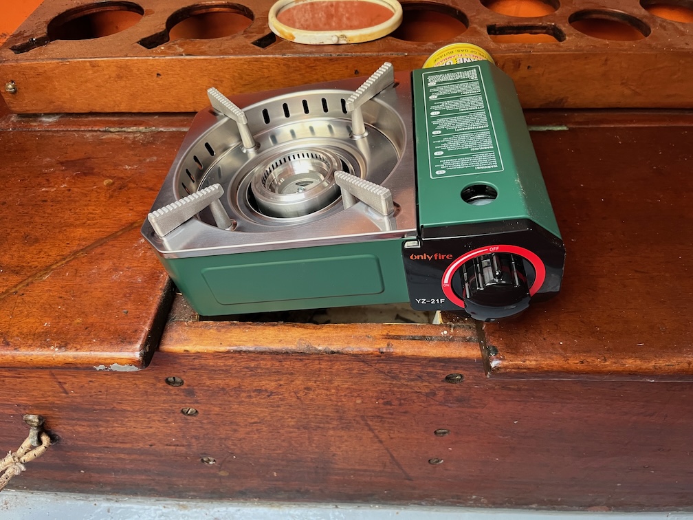
Now, none of these parts were on Shoal Waters when purchased and I’m not going to replace the stove with an exact replacement. Instead I’m going to use a burner that takes the modern 200g canisters since this will allow me to store the spares outside of the cabin. However, the space available for such a burner is quite small and the size I use for camping is too large.
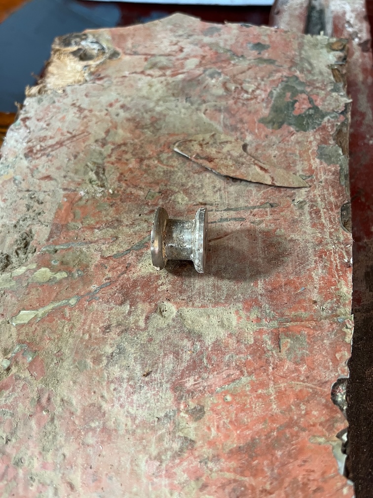
Not to worry, a quick internet search found a much smaller unit.
The difference between this and the larger, more common variant, is that there is no lever mechanism to pull the canister into place. Instead it is held in place by a magnet.
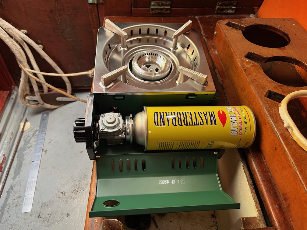
Now, my intention is to make a box to hold the stove that is just a little bit deeper than the stove plus canister, so that the canister cannot move away from the magnet which might happen in a bumpy sea.
The stove is also a bit wider that the space that held the old gas cylinder and that will mean rearranging the lockers slightly.
The stove plus canister is also a bit deeper that the locker, as you can see here.
However, the gas cylinder locker is a simple box screwed to the side wall, so making it wider and deeper will not be too much of a chore. The hardest part will be removing the lid of the locker forward of the burner to cut a section off to make space for the wider burner box.
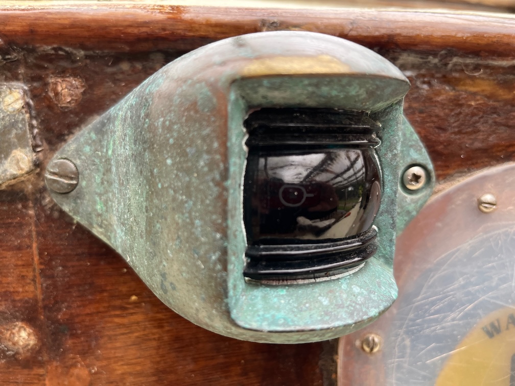
I started looking at the navigation lights as I need something small to be getting on with since I have hurt my right foot. When I get tired I make mistakes and last week the mistake involved the foot and a solid metal support meeting at a high enough relative velocity to break open the wound remaining from the surgery a few months ago. So, no kneeling down on the inside of the boat trying to work on the centreboard case. I’ll have to wait until I can comfortably flex the foot before continuing with that.
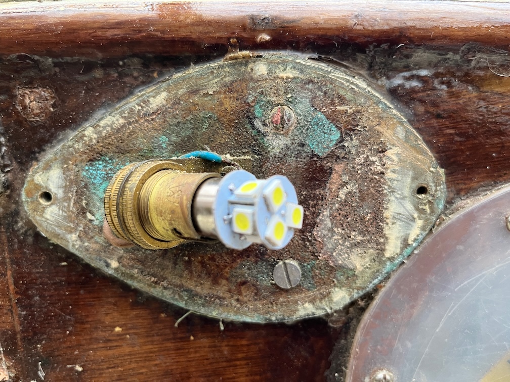
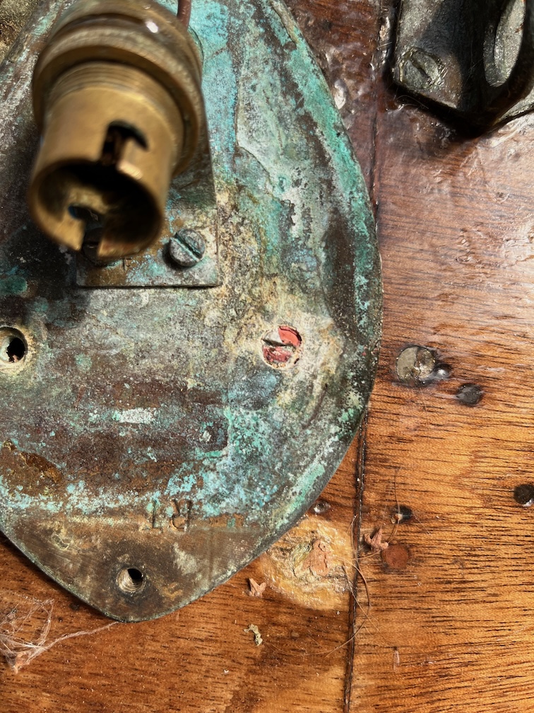
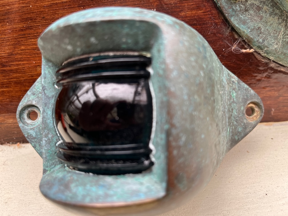
One of the things I’ve done as part of the refurbishment is to buy LED replacement bulbs for the lights to cut down on battery drain.
This is the original bulb, fairly standard.
And this is the new LED bulb. It occured to me that the back of the light, as you can clearly see from the photo, is not at all reflective and thus the nav lights will be dimmer than they could be. I asked on the Dinghy Cruising Club Forum, of which I am a member, for suggestions and these boiled down to two main options. Crumpled aluminium foil and a plastic mirror cut to shape, both of which are possibilities for the tools I have.
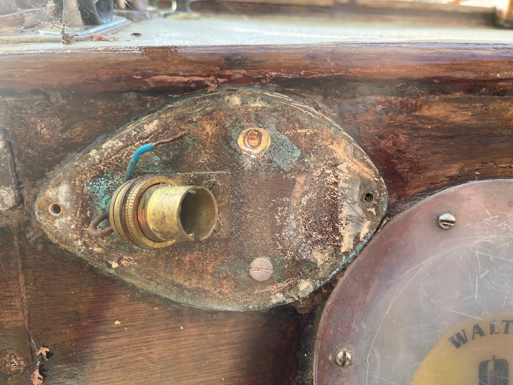
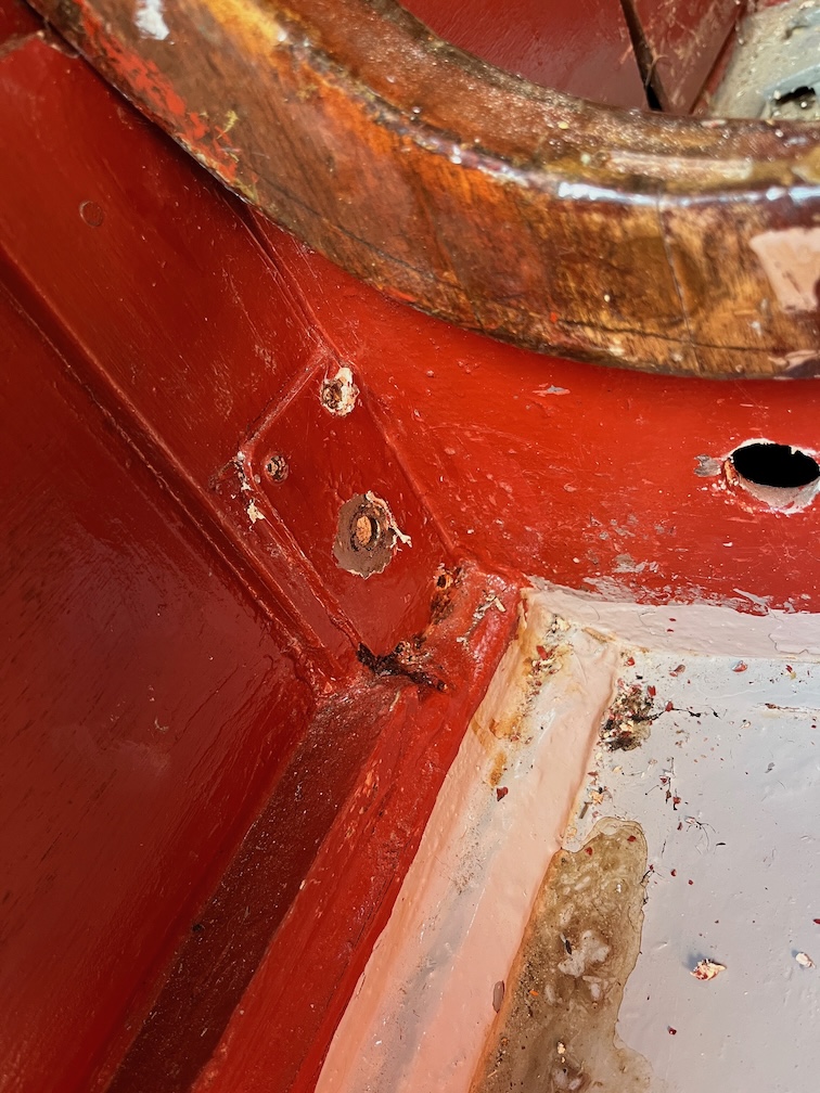
However, before I test out these options, I really need to do something about the fixings. The two bolts holding the base plate to the cabin side need to be removed. One is brass, well it was and is now copper, and the other is stainless. This is the same on both sides. Not sure why but they need to be taken out. The ex-brass one to be replaced and the stainless one removed to allow the base plate to be countersunk such that the head of the machine screw does not protrude.
The head of the brass bolt was drilled with a shallow hole and then countersunk as can be seen here. A small diameter drill bit was used to drill a hole right along the length of the bolt and then opened up using successively larger diameter bits until the entire bolt was removed.
In this photo you can see that the lower, stainless steel bolt has been removed and the upper brass bolt remains.
It didn’t take long to remove the upper bolt, just a steady hand to prevent the drill bits from breaking.
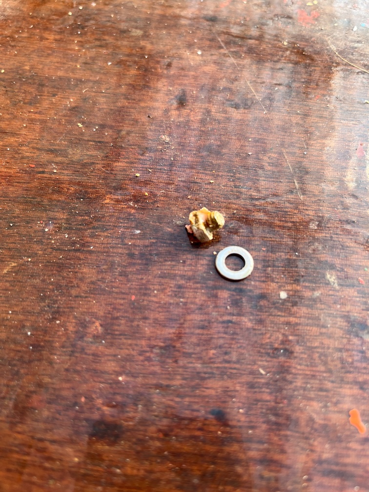
Here is the remains of the bolt, the nut and washer.
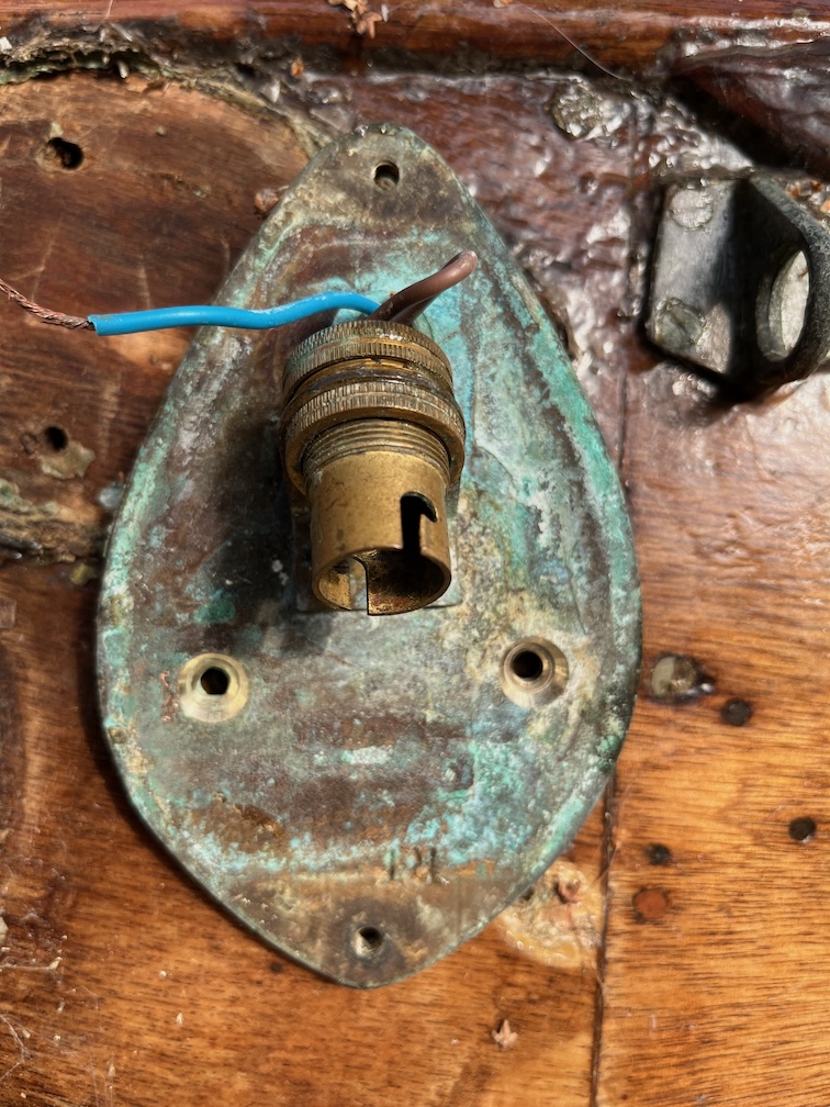
The nav light on the opposite side was done in the same fashion except on this side, the lower bolt was the brass one and the upper one stainless steel.
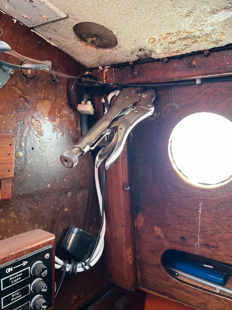
I used vice-grips on the inside to hold the nut whilst I unscrewed the bolt from outside for the stainless bolt, but the other one had to be knocked out. I did this on the first side as well but forgot to take photos.
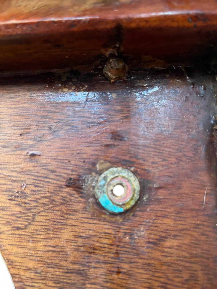
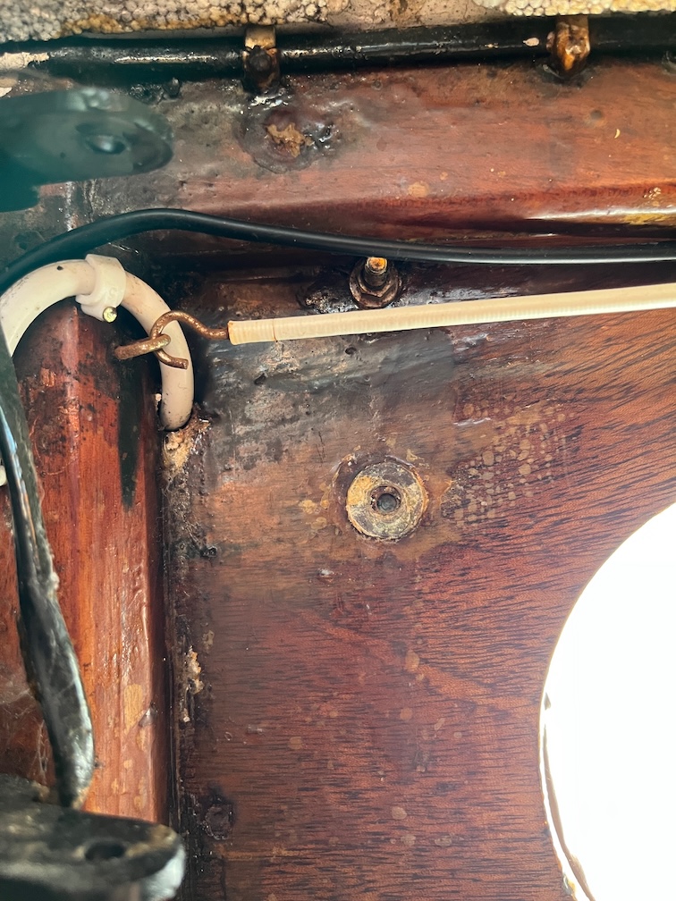
The brass bolt and nut had degraded into copper and at some time in the past it has been knocked off, as can be seen in the photo, just leaving a short length of the bolt in the wood of the cabin side.
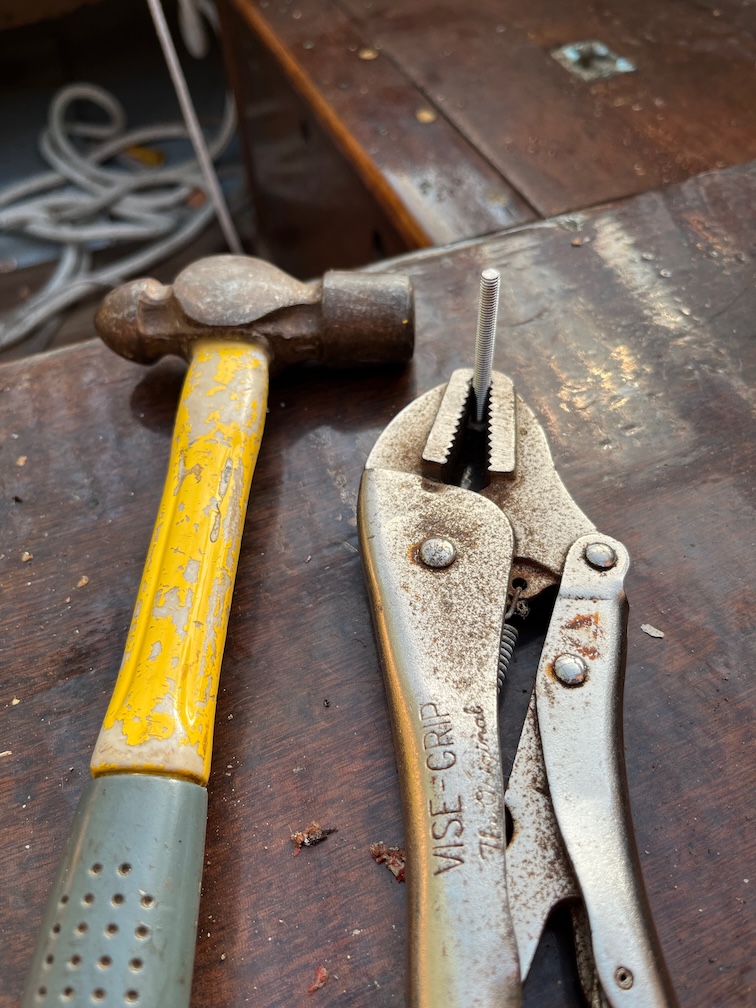
I used a bolt as a drift and gently hammered out the remaining bolt from the inside. The vice-grips are to stop me from hitting my hand which probably would have happened if I had held the bolt and tried to hit it.
In the end, the bolt stayed in the base plate which itself came loose from the cabin side. Still, the copper bolt was easily remove with a gentle tap on the reverse with the hammer.
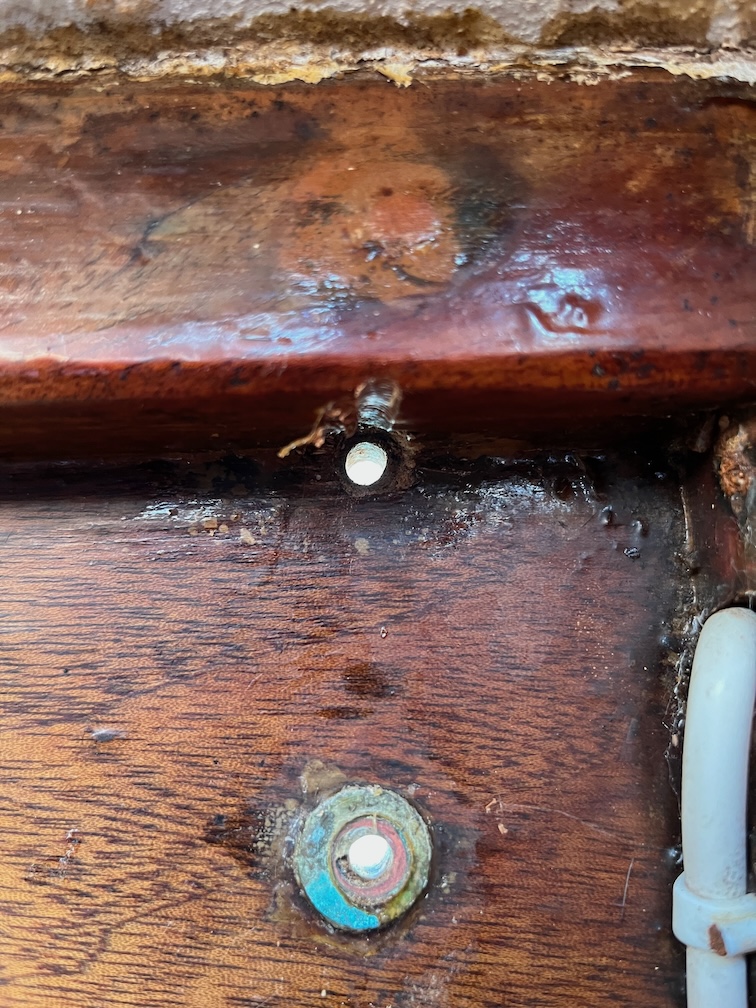
The two holes were then countersunk as you can see. I gently drilled the countersink, taking off a little at a time and offering up a machine screw of the correct size each time to check that I didn’t remove too much of the base plate. The other side was similarly countersunk, but you don’t need to see a photo of that as it’s more or less the same as this one.
So far, so good. I only had one machine screw of the correct size so the next thing to do was to order more. With that done I turned my attention to the outer casing fixings.
From the photo above you can see that one of the fixings is a knurled bolt, presumably original, whilst the other is a stainless steel wood screw that goes through both holes in the light and into the side of the cabin and this is the case for both nav lights. I presume that the lights had two of the knurled bolts each and that over time two had been lost and were replaced with the screws.
Time to fix that.
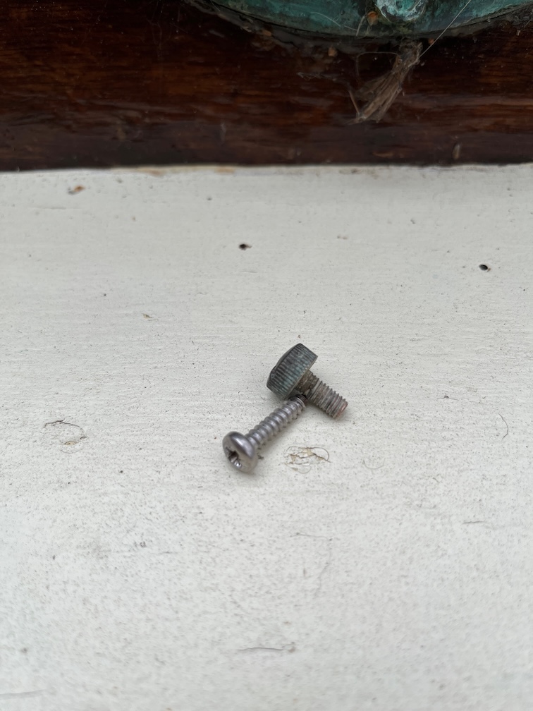
These are the fixings. The screw will be replaced but I could only find brass knurled bolts that will fit.
The problem is the recesses in the casing. The heads of the knurled bolts measures 11.2mm in diameter and although I can find stainless steel knurled bolts, only the brass ones have a head that will fit into the recess. Even then it might be tight as those have a head diameter of 12mm, so it’s going to be close. Also, I think that the nav lights are bronze, not brass and I’d really like to have bronze replacements. However, those would have to be custom made and that would be exceedingly expensive. This is also why I was looking at stainless ones.
Never mind, brass ones are on order and I’ll liberally coat them with some thing when I reassemble the lights to slow down the leaching of the zinc from the brass over time. The pack also contains 5 bolts so I’ll have replacements until I can find bronze or stainless replacements.
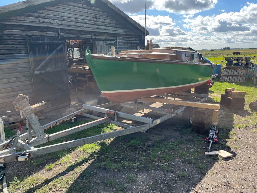
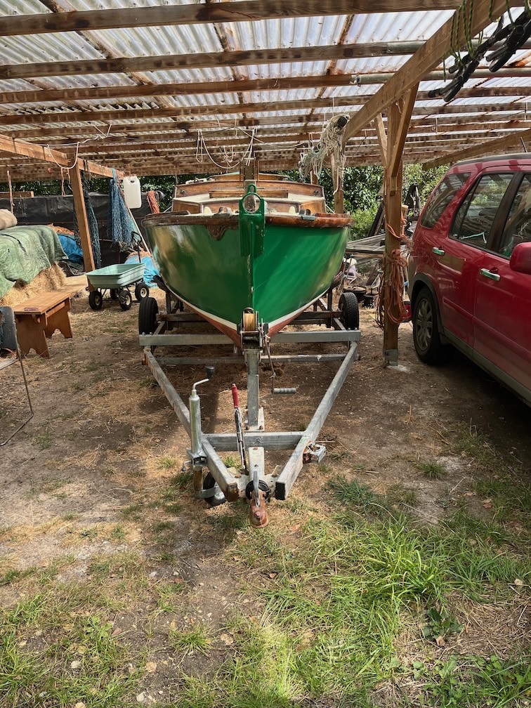
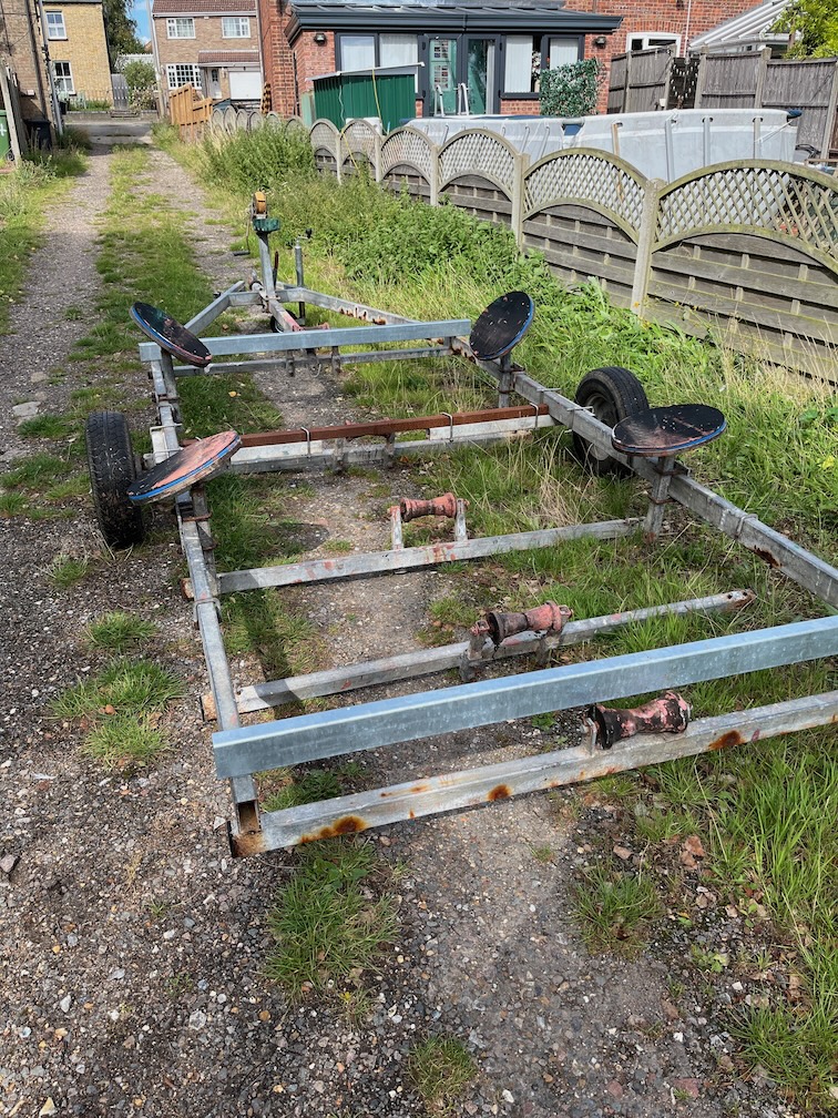
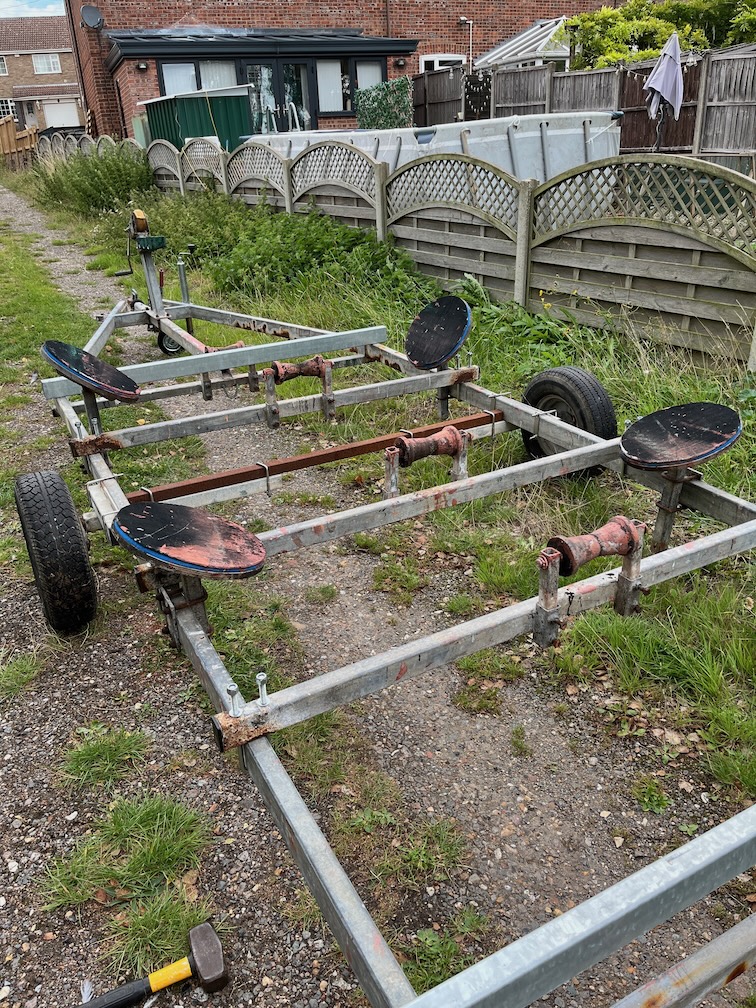
The time has come to move Shoal Waters from off the hardstanding in front of the workshop and into the Hay Barn.
Here’s the reason why. It’s not easy trying to work on the boat when she’s open to the elements. This was taken a few days ago and, to be honest, it doesn’t rain this hard very often, but I think you get the point.
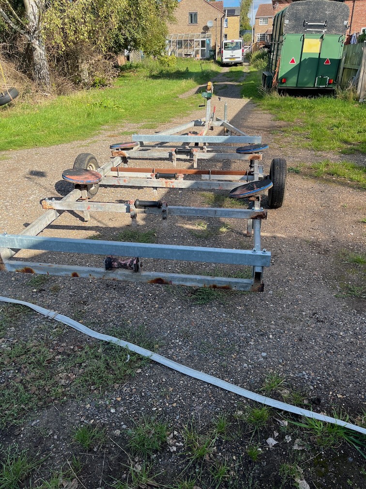
So, today’s boat task is to put Shoal Waters onto the working trailer and move her into the Hay Barn.
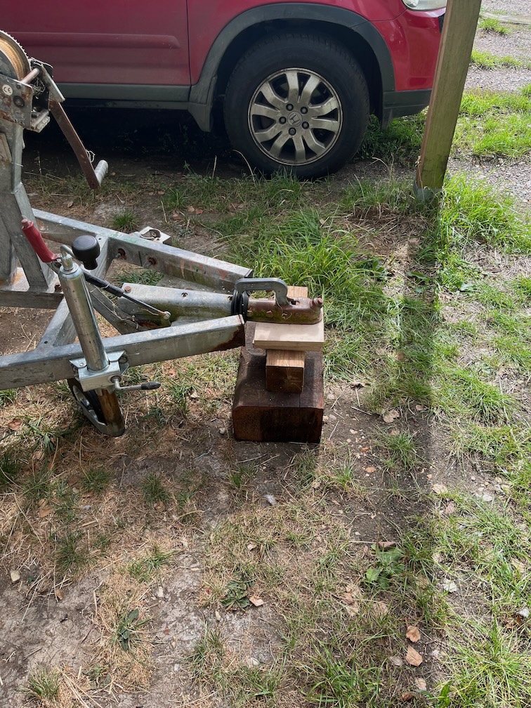
First things first, move the trailer close to the boat.
Then jack the boat up using a specially made beam to form the bridge at the front.
The beam bent a bit as you can see here, but not enough to worry about just yet. However, before the next lift I’ll reinforce the beam, probably with a length of 6mm steel bolted to one or both sides. For now it’s good enough as the wood is not old and therefore still quite strong.
With the hull lifted up sufficiently, the trailer could be rolled underneath the boat. This wasn’t as tedious as getting her off the trailer a few weeks ago, but still tedious enough to make me want to find a better way to do this before the next lift is required.
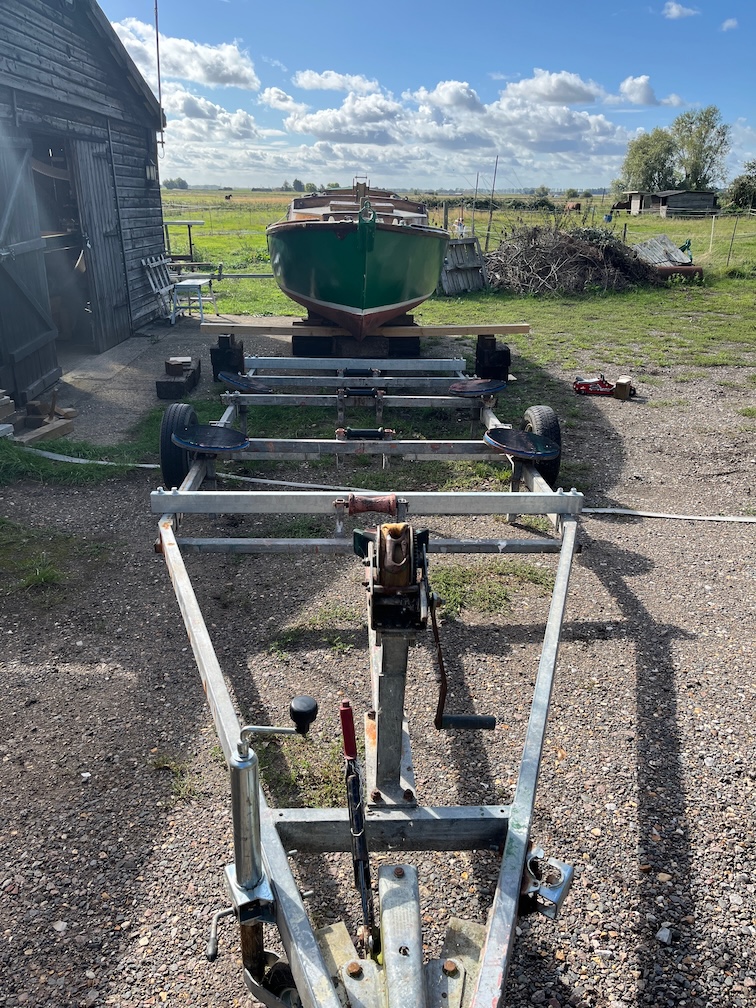
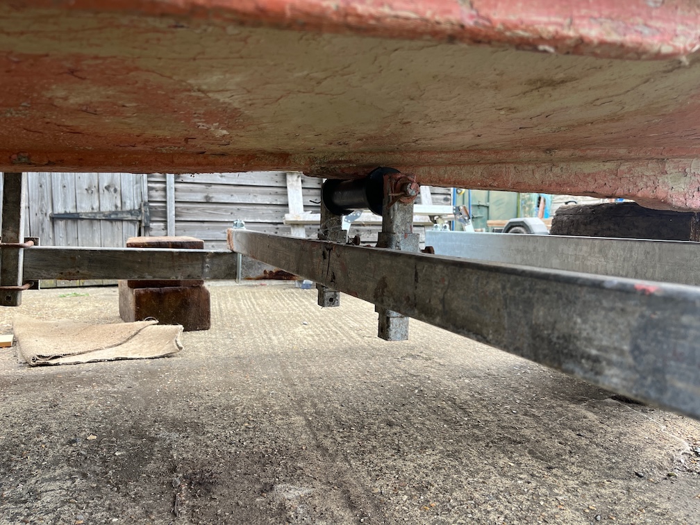
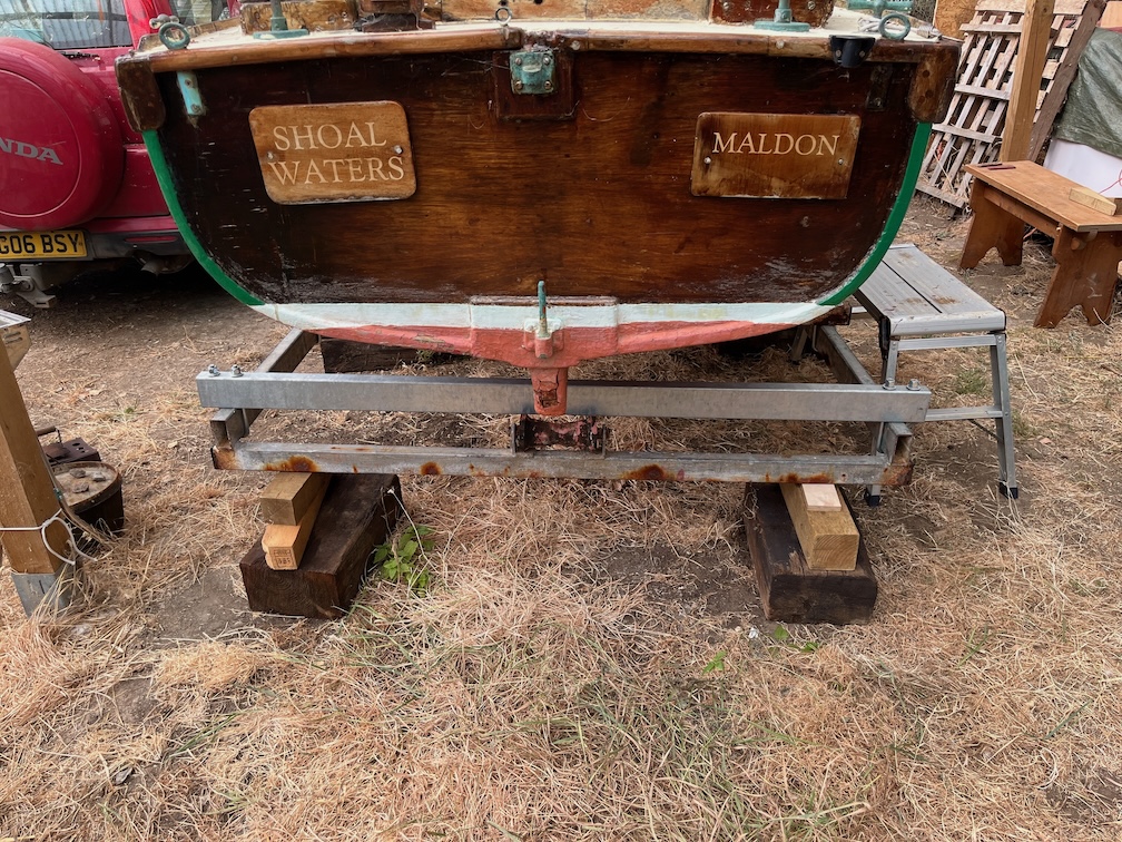
Finally the boat is on the trailer, the side supports are bolted in place, the centreline rollers adjusted and the beam removed.
Once one of the rollers touched the keel, the others were lifted to also touch and then bolted in position.
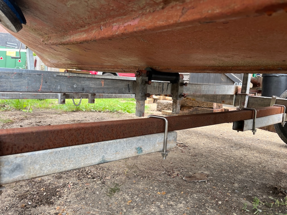
a thin piece of wood was put onto the front new cross beam but it wasn’t quite thick enough as you can see. Once Shoal Waters is in the barn I’ll fashion a better filler for both the new cross beams as these do not have rollers.
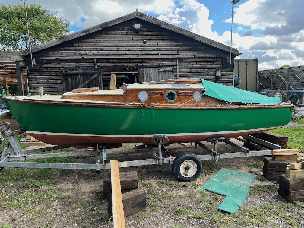
And finally into the barn. Here she is protected from the elements and the only thing that needs to be watched is your head when climbing in and out of the boat.
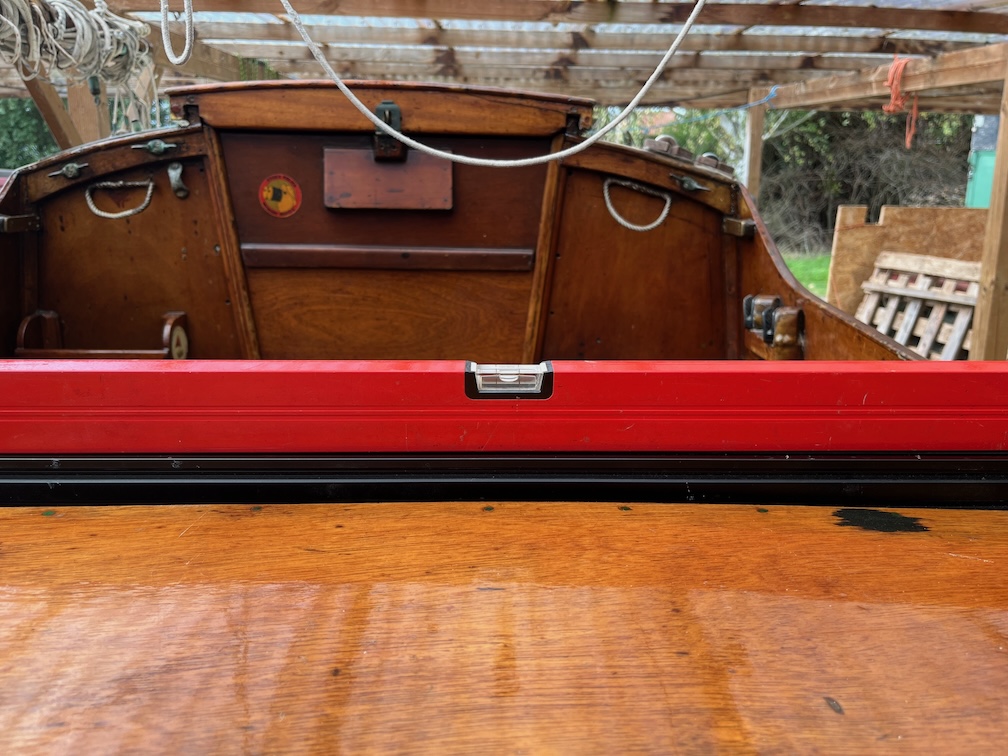
As usual I used a spirit level across the aft end of the cockpit to level the boat.
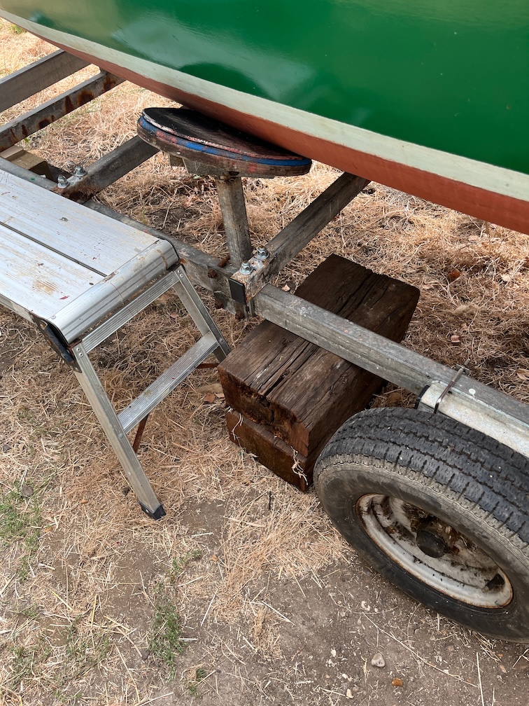
The trailer being blocked up just behind the wheels on both sides.
The port side blocking is about 75mm or 3″ taller than the other side due to the slope of the ground underneath.
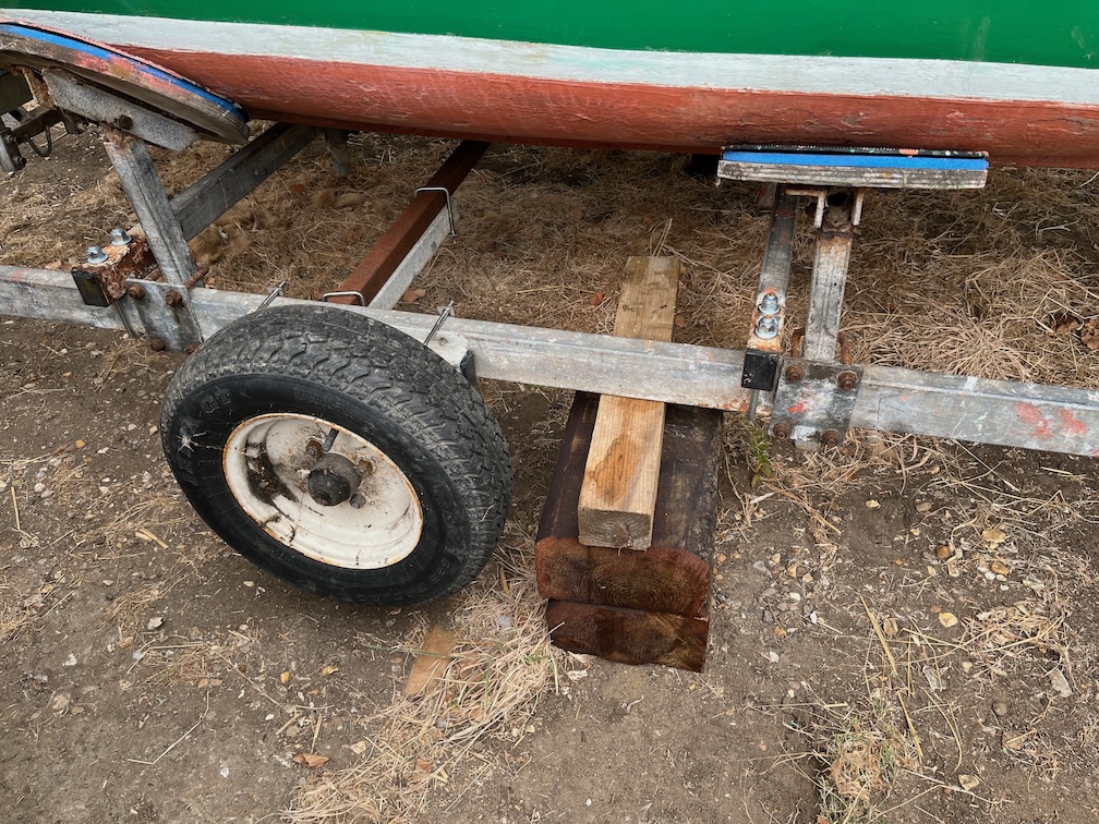
Blocks were also added under the towing hitch…
…and under the back end of the trailer. This makes the whole thing very stable and the boat does not rock or threaten to tip over when you climb in and out.
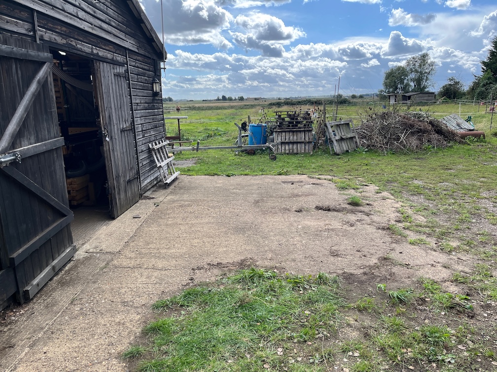
The hardstanding is now clear of the boat…
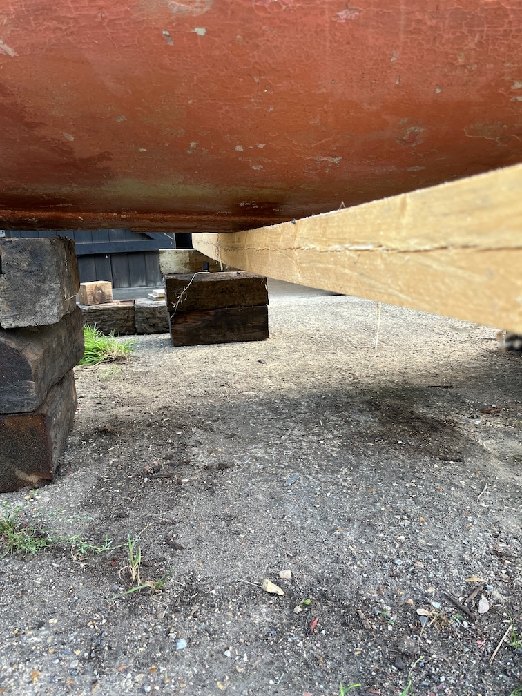
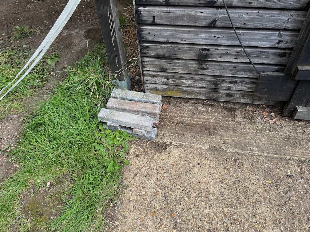
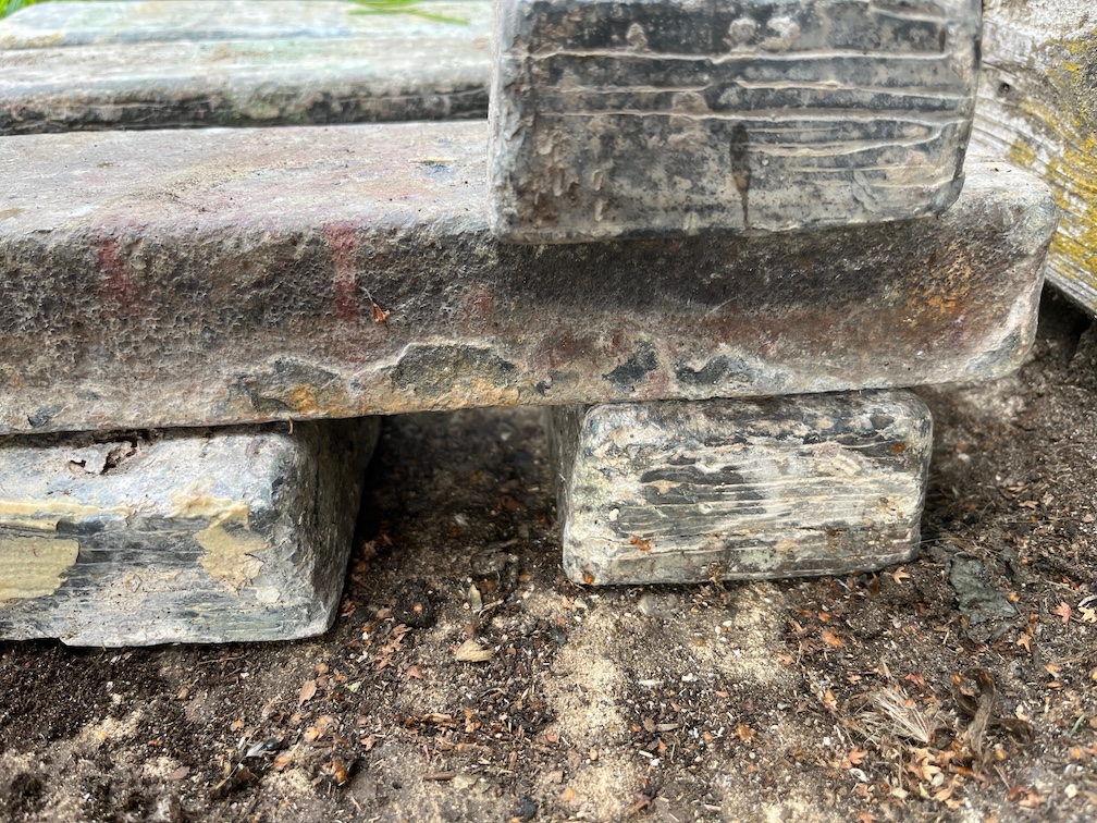
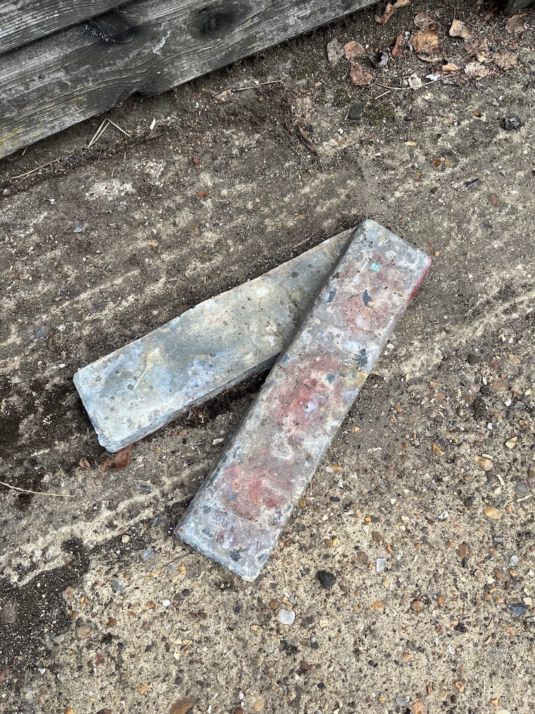
I even put away all the wooden pieces that were used to block up the boat and trailer at various times. What is left is the lead ballast. I need to decide what to do with this. When it was originally cast by Charles Stock he had to melt the lead is stages, pouring each pot into the mould before melting the next.
This, unfortunately, meant that the layers only partially bonded together, you can see the layers in the ends of the pieces…
…and one has come apart. I should probably melt these down one at a time and recast them to the same size but in one go to get rid of the delaminating problem.
Still, that’s for another day. for now, Shoal Waters is under the barn roof and I can continue working on her without having to worry about the weather.
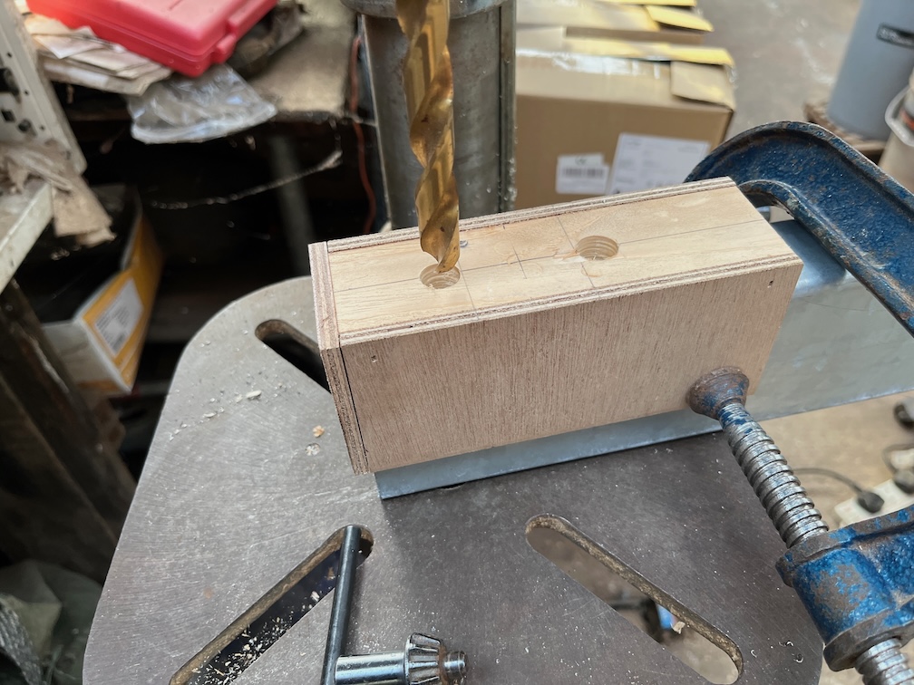
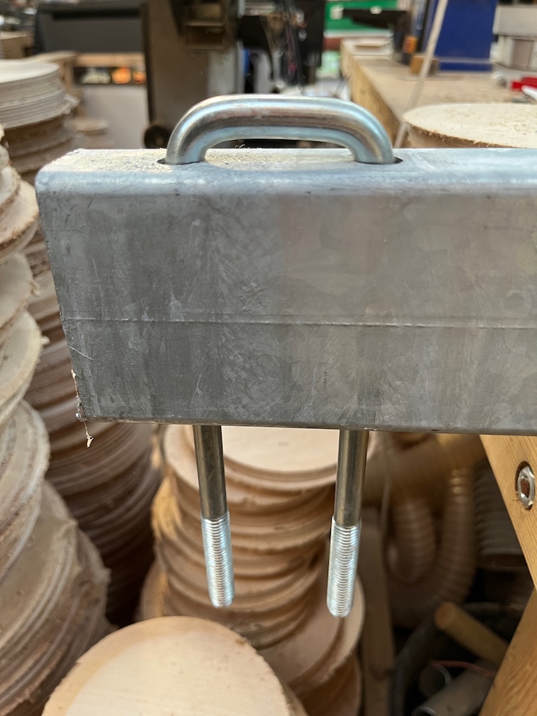
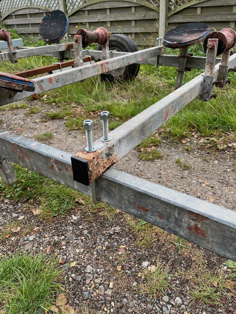
Today’s task, or at least the Shoal Waters related task since I have other tasks that I wish to carry out today as well, such as building a rope maker, is to drill the holes into the ends of the two new cross beams and then cut down and fit the u-bolts.
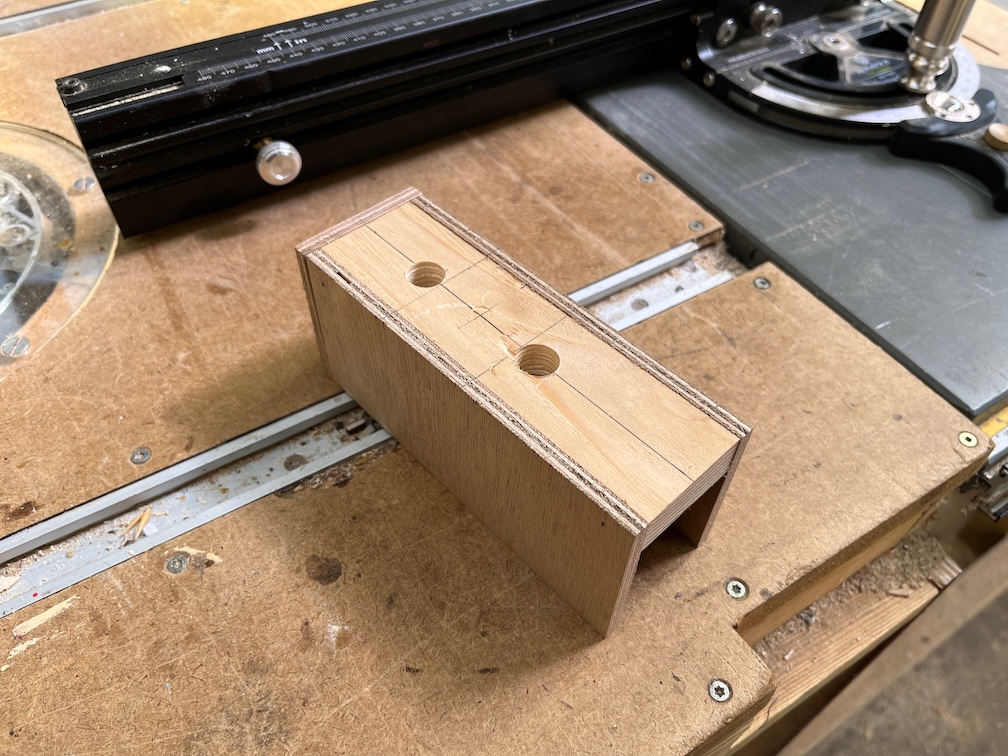
This is the jig I used to locate the holes in the correct position. It fits over the end of the beam and guided the drill bit until a small indentation has been cut into the metal. The jig is removed and a small diameter bit is used to drill right through the top wall of the beam. This was repeated for all four beam ends. After that the correct sized hole was drilled using the indentation to center the bit.
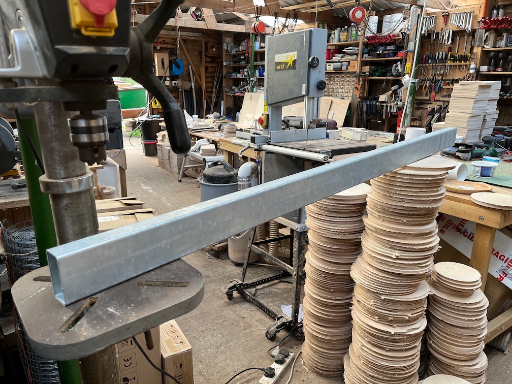
The next part of the process is to take a cross beam into the workshop and put it onto the drill press, supporting the other end to keep the beam perpendicular to the drill bit.
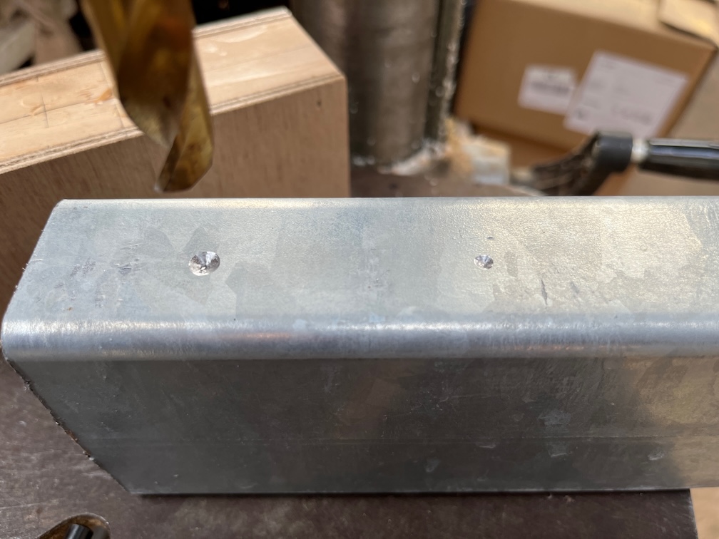
The jig is clamped to the end of the beam and the correct sized drill bit used to make an indentation in the beam. This is done on both ends and on both sides of the beam.
Here is the result of one end. The size of the indentation isn’t critical, it’s just there for the next stage.
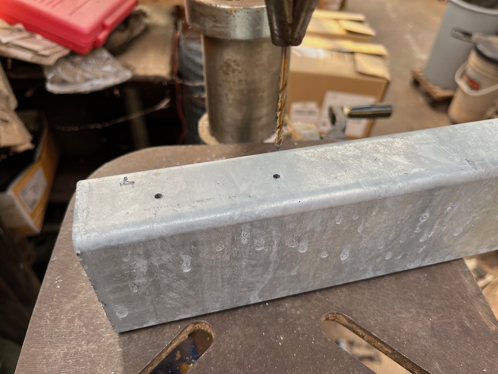
A small hole is drilled through the wall of the beam, in this case a 3mm hole as this is the smallest bit the drill press will hold. Again this is done on both ends and both sides.
The large drill bit is then used to open up the hole to the correct size.
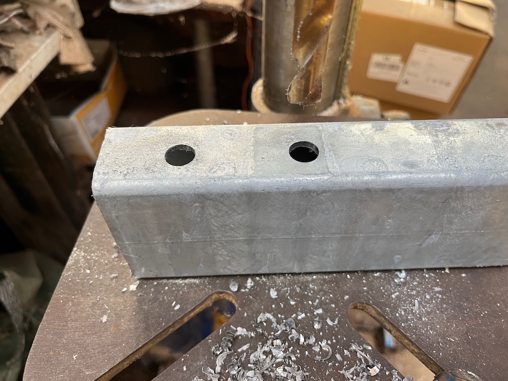
This results in a perfect fit for the u-bolt, which was the intention. This shows how a simple jig turns a complicated job into something a lot easier to achieve.
Finally, the u-bolt legs are cut to size and the beam is bolted securely onto to the trailer.
I only had time to do one of the beams this evening, I also spent some time using the CNC Route on another task which I also didn’t finish. Both of these tasks will be completed tomorrow.
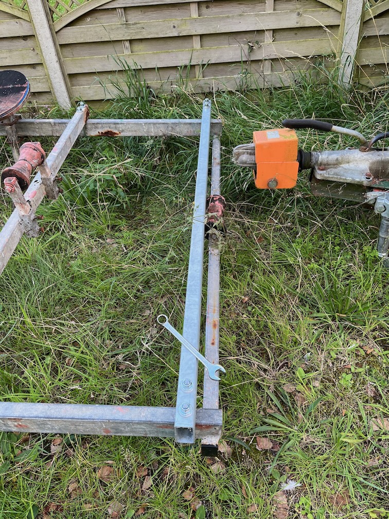
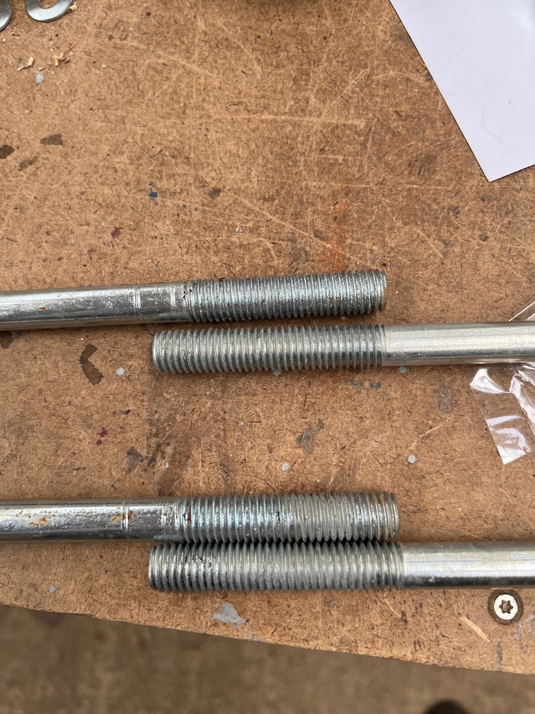
Just a quick update to the work on the working trailer. The M12 penny washers arrived late on Monday afternoon so I wasn’t able to get the work done then but had to wait until this afternoon instead.
The task for today was quite simple. Cut 35mm off each of the legs of the six u-bolts and use the shortened bolts to fix the cross-beams to the trailer in the place that I need them to be, which is on top of the side-beams.
This is the first of the six done and you can see the two M12 penny washers underneath the standard M12 washer upon which the bolts sits, ensuring that there is enough thread to give a strong joint.
It didn’t take long to do all six u-bolts, about an hour all told and here are the cross beams now done. I will paint the cut ends of the bolts with something to prevent them from rusting, but that will have to wait for a dry day.
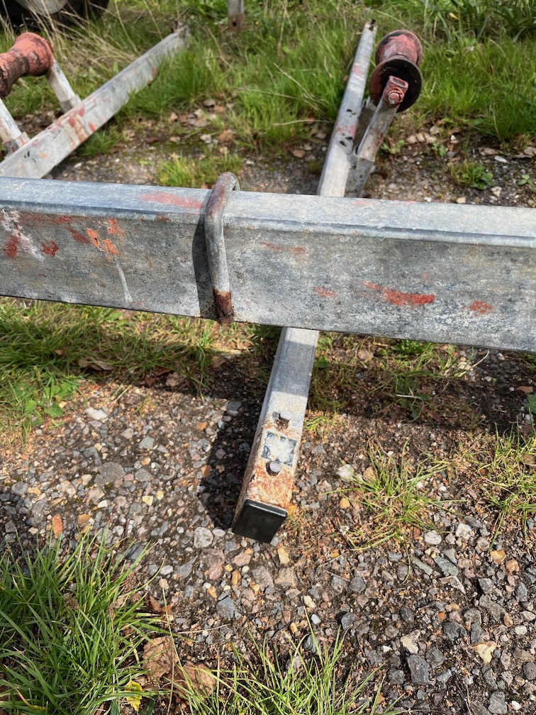
The taxt task on the trailer is to fit the two new cross-beams and for this I need to drill two 13mm holes in each end of the beams and these need to be perpendicular to the beam and as a result parallel to each other. Not only that but they must straddle the side-beams exactly both ends otherwise the u-bolts will not fit.
This will be a case of measure about a dozen time to absolutely ensure that the holes will be drilled in the correct place before actually drilling the holes. This suggests a jig that slides over the end of the beam so that the holes, drilled through the holes in the jig, are in the same place from the ends of the beams which are almost exactly the same length. By almost exactly I mean less than 1mm difference, which is close enough.
There’s not been much work done on Shoal Waters for the last seven weeks, I had minor surgery on both feet which has meant I’ve been unable to walk properly due to the dressings and the discomfort, if not outright pain.
Now that my dressings have changed to less obtrusive ones and I can walk, sort of, I can get on with things that do not require me to wear shoes, that’s agony, nor kneeling down as putting my feet in that position is also just a tad painful.
However, the work needs to get started as the evenings are getting darker and I still have a great deal of work to do.
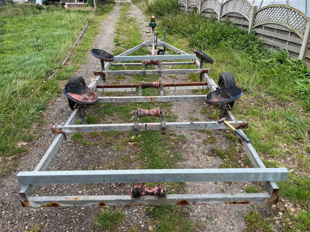
Today’s task is to start work on the trailer.
In order to work on the railer I needed to move it out of the weeds that have grown around it and onto the drive so that both sides are accessible.
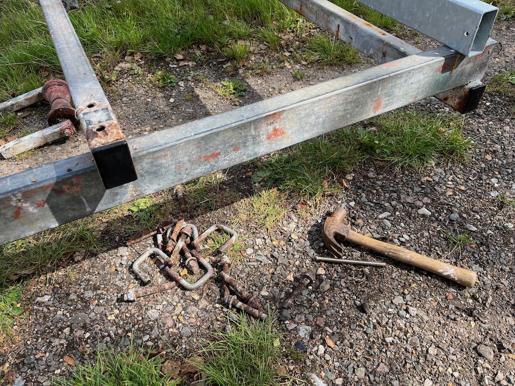
Each of the u-bolts holding the three under-slung cross-beams were cut using an angle grinder. I could possibly have removed a few of the nuts but to be honest, that would have been a lot of work for a only a little gain, so I bought a pack of 20 metal cutting disks for the angle grinder from Amazon yesterday and once they had arrived today I was able to get going.
Then each of the legs of the bolts were drifted out with a hammer and drift. One or two of the legs had to be hammered really hard to get the to move due to the rust, but they all came out eventually.
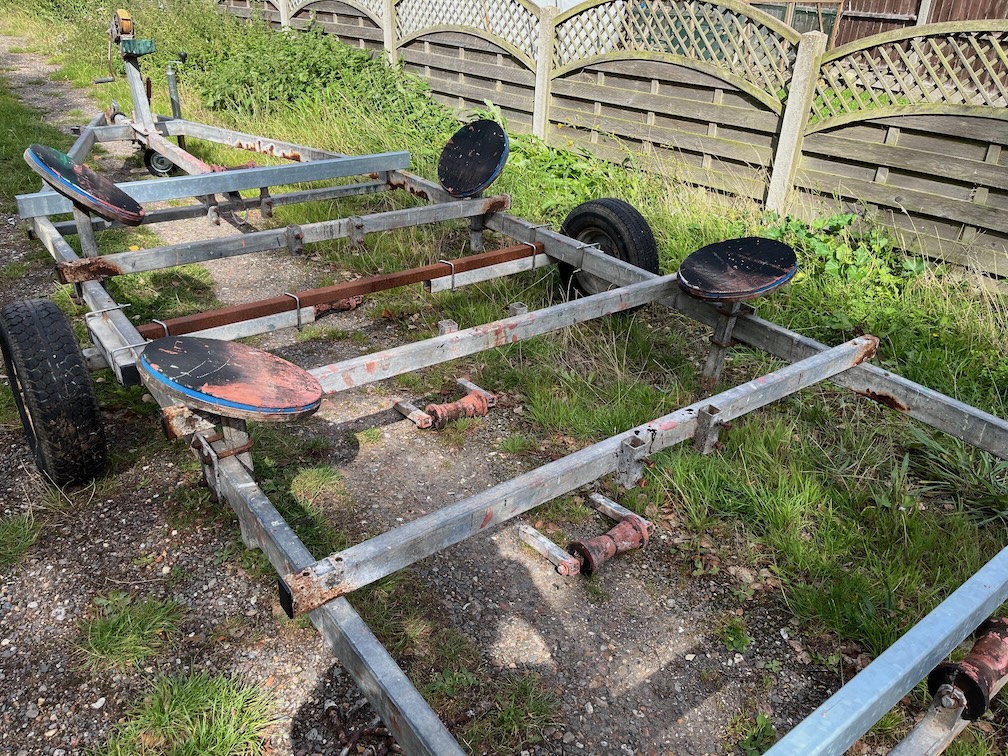
With all the rusted u-bolts removed, the cross-beams were put on top of the side beams. The rollers were taken out at this point as they tipped the beam over if left in place.
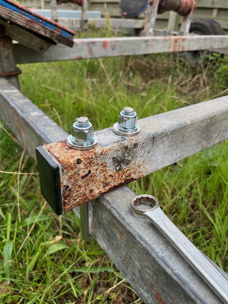
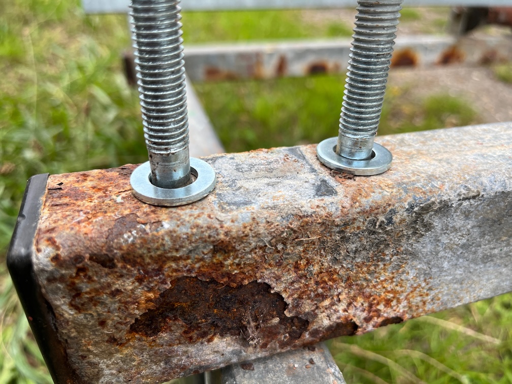
New u-bolts were then put into place as shown here. I was unable to get shorter ones that still fitted so these longer ones will be cut down once all is ready to be reassembled.
I didn’t tighten up the nus, they were just put on to stop the u-bolts from falling out.
The threading on the legs of the u-bolts is onlu just enough to allow the nuts to be tightened up, but I noticed that on one u-bolt the thread seemed to be short as you can see here.
Comparing it to one of the other u-bolts I have in the workshop, the thread on this u-bolt is certainly too short for these cross-beams. I’ll use that on one of the two new cross-beams which are taller than the three old ones, and use one of the other u-bolts with a longer thread.
As you can see, the thread now extends to below the washer.
However, the thread still isn’t really long enough and will stop the nuts from being tightened down completely, so I have ordered some M12 penny washers, which are 2mm thick and 30mm in diameter, to put under the smaller washer seen here. Two per leg will easily allow the nuts to be fully tightened down.
That’s all I’m going to do today as even walking around causes my feet to hurt and I’ve had enough. The next task will be to cut the legs down to the correct size once the washers arrive, drill two holes in each end of the new cross-beams and fit those in place. At that point it will be possible to but Shoal Waters back on the trailer and wheel her into the Hay Barn.
Mind you, I’ll have to clear out a space for her first as Naiad’s trailer is in there covered in various bits and bobs.
Having two trailers is a little bit of a problem in two ways. Firstly there is the nomenclature. Since both will be used for both boats at different times, calling them Naiad’s Trailer and Shoal Waters’ Trailer is technically not correct, so I’ve decided to call this one the working trailer and the other the travelling trailer. This one will only be used for working on the boats and the other will now only be used to transport the boats. Seems like a good idea.
Secondly, what to do with the trailer that isn’t in the Hay Barn? We don’t have any other space for it under cover and leaving it out all year. in all weathers round will cause it to rot away. So, I’ll also have to build a small shelter of some description for the trailer that isn’t in the hay barn. Two steps forward, one step back.
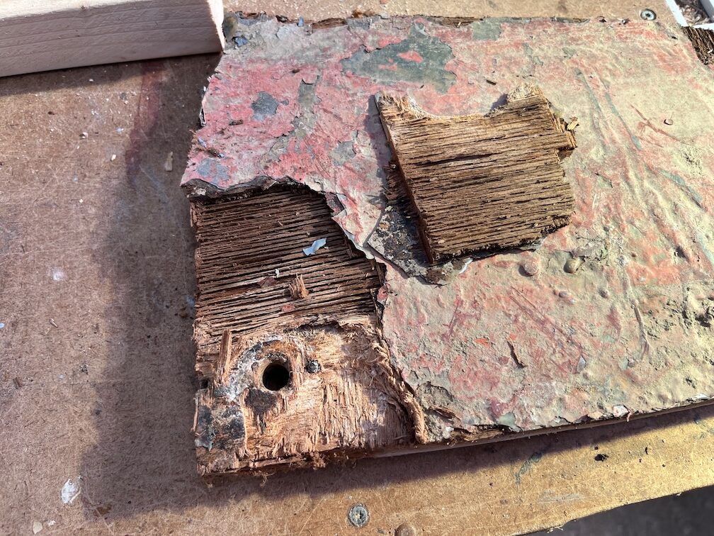
The title of this post is a little misleading, since what I’m trying to find is where the soft/rotten wood in the centerplate case ends.
In the above photo you can see where I have cut more of the side of the case away and exposed the diagonal end block. I think I have left just one veneer of the plywood on this block and it was very difficult to remove indicating that the plywood here was in good condition. I removed as much as I did so that the new sides will have a significant overlap and therefore a very good seal when it is installed.
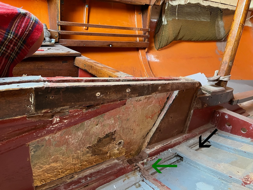
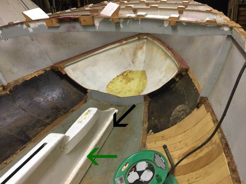
The black arrow points to the top of the keel and the green arrow points to a rounded piece of wood placed next to the case side and on top of the keel.
Contrast that with the same area in Naiad (more or less). Again the black arrow points to the top of the keel and the green arrow to the rounded bit. From the Naiad photo it is obvious that the side of the case goes down to the keel at the least and the rounded bit is there to strengthen the joint and to provide a good area for sealant.
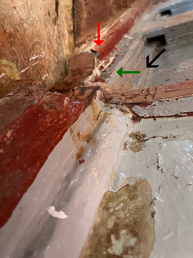
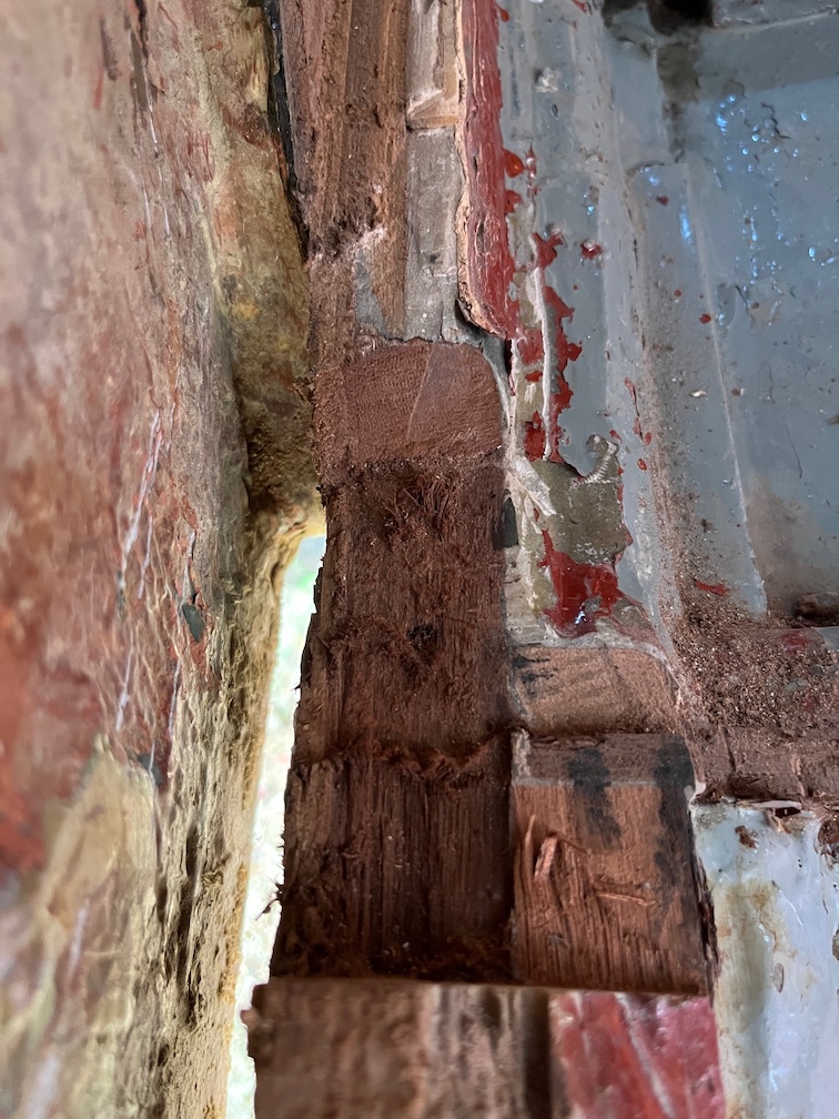
But in Shoal Waters there are two rounded bits.
Here’s what I mean. The black arrow points to the top of the keel, the green arrow points to the first rounded bit, equivalent to the one in Naiad and the red arrow points to the extra one. Now, was this original or put in by Charles Stock or Tony Smith? I don’t know but I need to find out how far down the plywood goes so that I can cut away the plywood but nothing else.
I’ve cut away a section out of the top rounded bit but it isn’t clear if the plywood extends this far or not. I’ll let the wood dry and clean it up with a sharp chisel. Hopefully that will show up the demarcation between the plywood and the Mahogany (?) rounded part.
Once that is done then I can carefully cut away the plywood and leave the rest untouched.
Before I go too much further, I should really measure the position of the pivot bolt hole. I’m doing all the exploratory work on one side only chopping away willy-nilly to find out the extent of the plywood. However, when it comes to the the other side I’ll know where cut and should be able to get the side out in one piece. More or less. That’s the plan anyway. That will allow me to use that side as a pattern for the new sides. However, I’ll still make a pattern as best I can once this side is removed just in case the other side doesn’t come out cleanly.
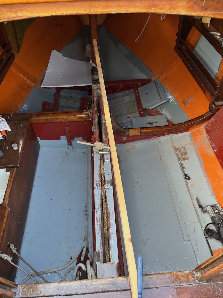
The next part of the centerplate case replacement is a bit technical, apologies for that, but has to be done before I cut away any more of the case itself. The first task is to measure as much of the case as I can and draw it out.
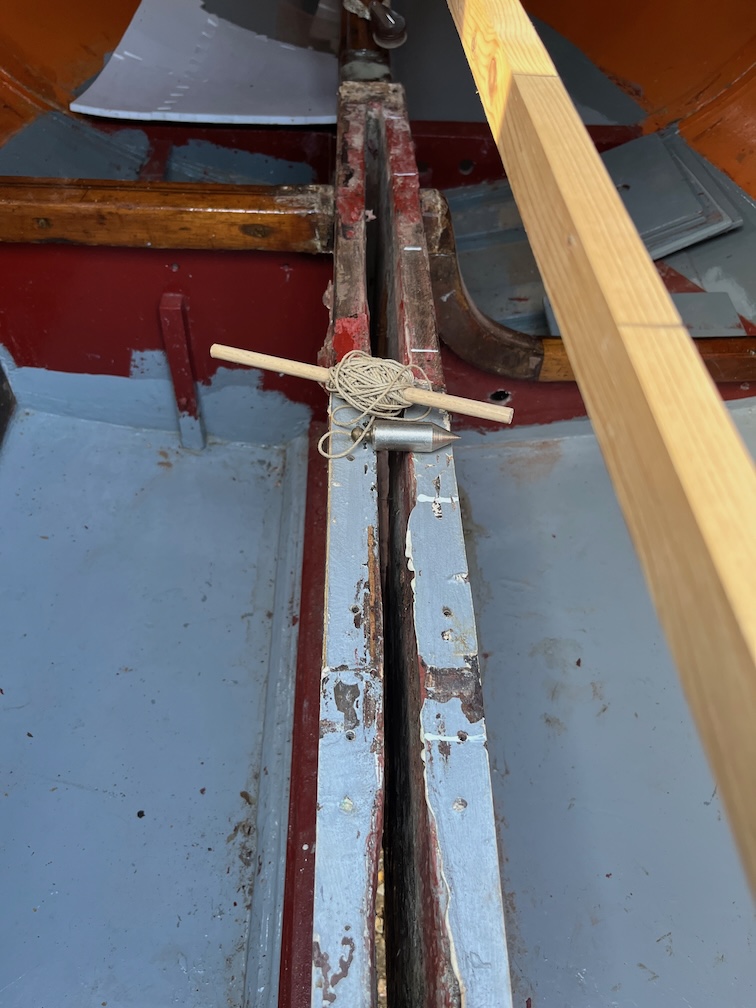
I marked a straight batten and 150mm (6″) intervals and then clamped it to the bridge deck such that the forward end was directly above the forward end of the case using a plumb bob to get that lined up.
Then I hung the bob from each of the marks on the batten in turn and made a mark with a white pen on the top of the case and on the bottom.
The marks on the batten.
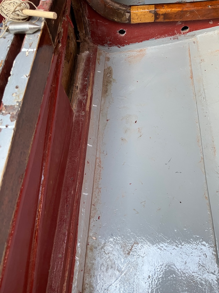
The marks on the top of the case.
And the marks at the bottom.
The final part of the measuring was to measure from the batten to the top and bottom marks and note these down. At this point it doesn’t have to be precise, with 5mm is close enough for now. Just as well as it’s really hot in the boat and I’m not really that limber, so it’s a bit awkward.
I then drew out the measured line in QCad, the drawing program I’ve used for years. The white line at the top represents the batten, the blue lines are the distance from the batten to the top of the case and the green line are to the bottom.
Then I added a straight line at the top of the case (in red) as I think this is straight on the boat, I’ll have to check, and fitted a smooth curve to the lines showing the bottom of the case.
Now, my CAD program shows me that this much of the case can be cut out of a piece of plywood that is 1210mm long ad 290mm wide. This is good news since quality marine plywood is sold in sheets that are 2500mm long and 1220 mm wide.
Now for the tricky bit. The original case was made from two 7mm thick pieces of plywood laminated together for a total thickness of 14mm. I can’t buy plywood of that thickness, so I have the the following choices. Three laminates of 5mm for a total of 15mm, two laminates of 8mm for a total of 16mm or a single sheet of 15mm thick. I did consider two 6mm laminates, but this will result in a case that is 2mm thinner than the original and although it would probably be fine, I’m not happy about making it thinner so I discarded that idea in favour of making it thicker, and therefore stronger.
I want to cut the pieces on the CNC router so that I have accurately cut, identical pieces, and since my router table is 1270mm x 1270mm square, I’ll not be able to cut a single side at a time as the entire case will be around 1800mm. The above drawing only goes as far as the start of the cabin whereas the case itself protrudes into the cockpit. But this section is certainly not so tall as the rest, so for the purposes of deciding how much plywood I need I only really need to find the tallest part of the case.
So that eliminates the 15mm thick plywood and I’ll have to cut shorter sections and glue them together. The choice between the three 5mm sheets and the two 8mm sheets comes down to the cost. Two sheets of 8mm ply will cost a total of £265.80 whereas three sheets of 5mm will cost £342.18, a significant difference.
There will be plywood to spare after cutting the case pieces out and these will be used to replace the bulkheads that reinforce the case.
These can be seen in the above photo. Cutting these away will destroy them no matter how careful I am, so these will be replaced. They have to be removed as otherwise I’ll not be able to cut the case away from the keel.
The next part of the decision making is how to laminate the pieces together. I’ll join the parts together lengthways using what is known as a puzzle joint since trying to cut a scarf joint in 8mm ply is far beyond my capabilities and as the sides of the case do not bend, a scarf joint would be an overkill. A simple butt joint would work but the puzzle joint increases the glueing surface greatly and that results in a much stronger joint.
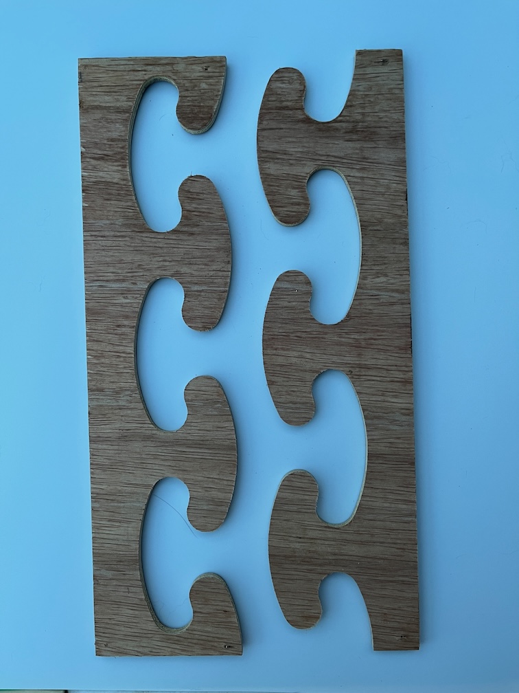
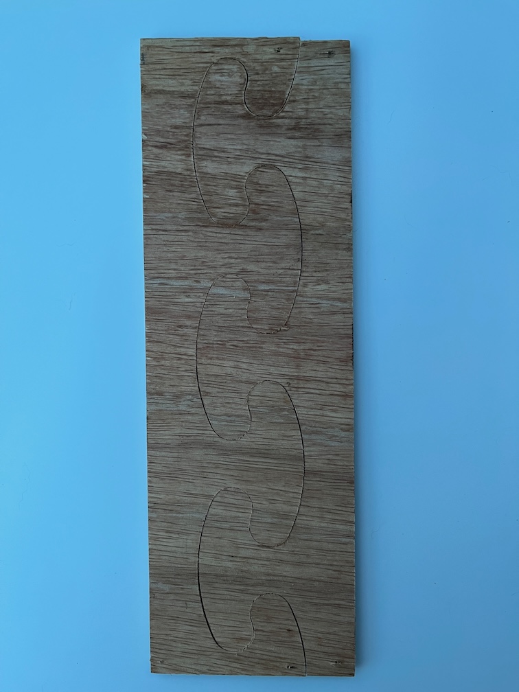
Here is an example of a puzzle joint that I made when trying out cutting the joint on the CNC router.
And here is the joint put together. As you can see, it’s not only a very good fit but is self-locating in that it won’t pull apart even without any glue in the joint.
So, that takes care of joining the pieces together but laminating them is another issue. The join between the two laminates much be perfect. No skipped areas of glue and no voids and there is really only one way to do that for a hobbyist and that is a vacuum bag. You get a piece of plywood around 25mm or an inch thick that is flat and slightly bigger all round than the laminates which are glued together and pinned so that they don’t slide over each other You put the laminates on the thick flat piece, put the whole thing into a plastic bag and suck all the air out. This forces all the pieces together and since one of them is thick and flat and won’t bend whereas the others, which are thinner and will bend, the laminates are pressed against the flat bit and will also be flat once the glue dries.
That’s the hand-waving, brief description. You’ll see how it works when I get to that bit and take photos.
Anyway, for now the technical bit is done and I can proceed with the removal of the rest of the damaged case.
I had some work to do on the CNC Laser after work and while that was running I decided to look at some of the pieces I removed from the top of the case yesterday.
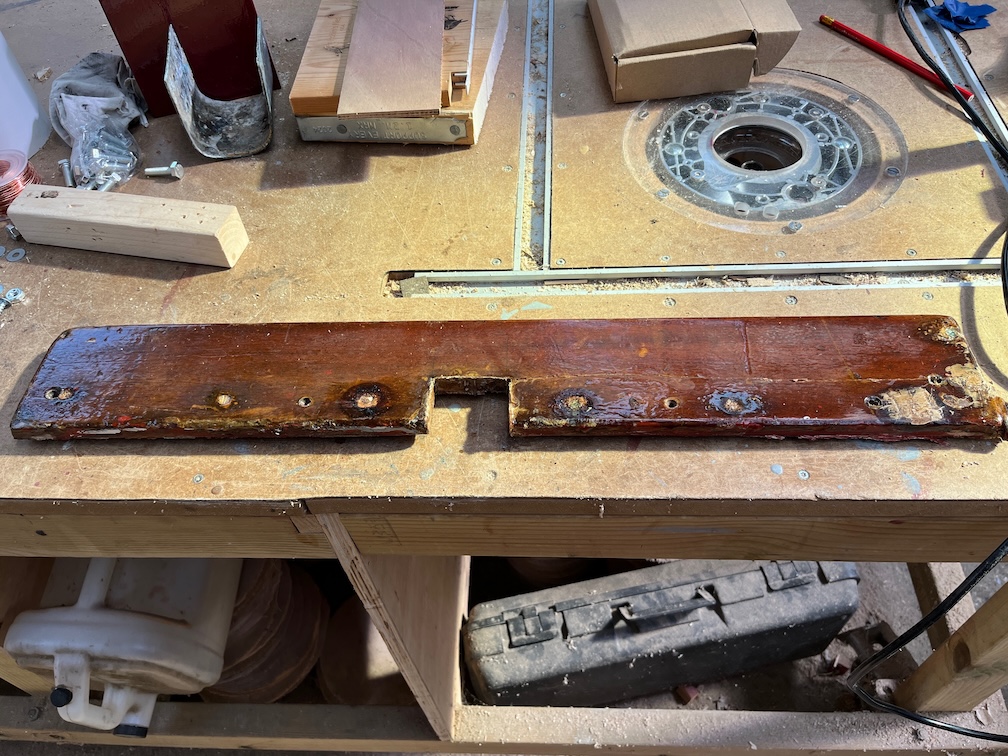
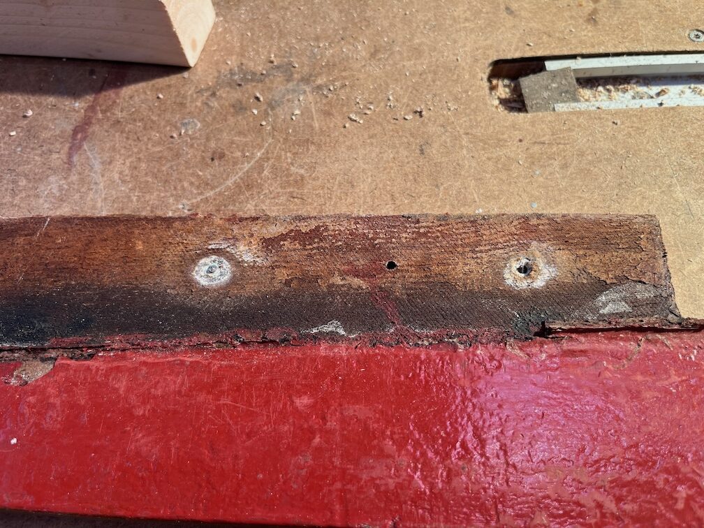
This is one of them and exhibits one of the things that Charles Stock did consistently wrong when building and maintaining Shoal Waters. He used brass screws. You can see the result in this piece of wood quite clearly, the discoloured circles of wood around the places that the screws were put originally.
This is the view from the other side and you will see that either the screw is missing completely or the zinc has leached out of the brass leaving just copper. These copper fastenings need to be removed and the wood repaired before it is put back in place. Still, enough of that, it was time to move back to the centerplate case. Armed with a multitool with a sharp, fresh blade I set to.
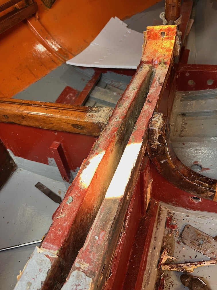
This is the result, a hole in the starboard side of the case. I had to say that it was either a very sharp blade on the tool or it was distressingly easy to cut through the side of the case.
This is the section that I cut out viewed from the inside face.
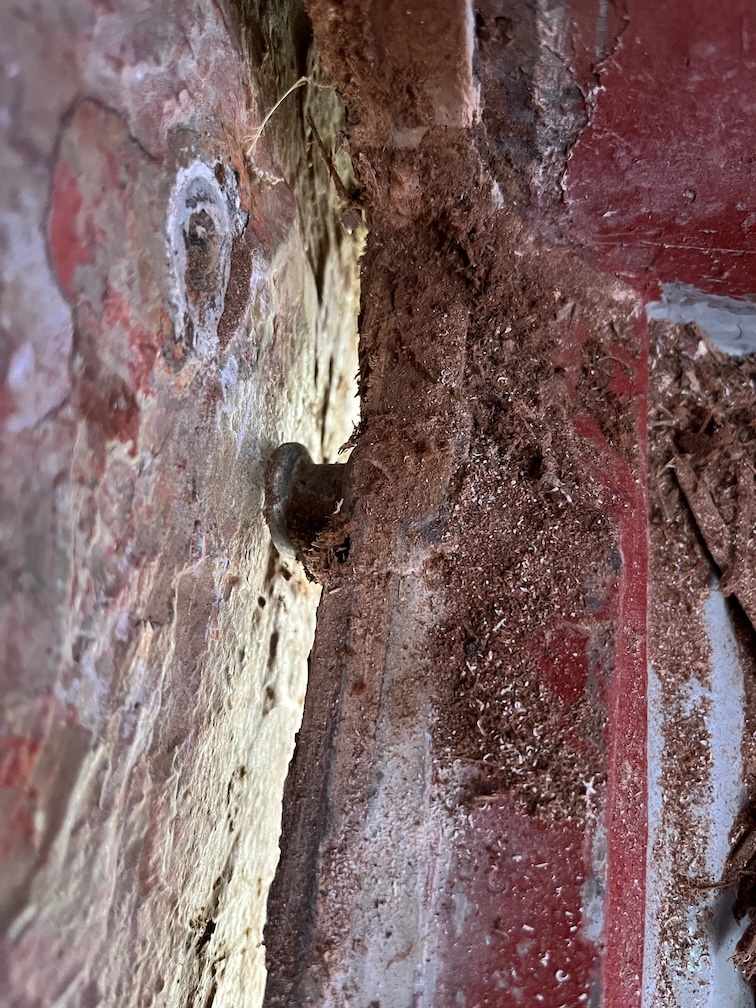
Looking down the slot through the opening I could easily see the metal spacer and it was easy to fish out with just my fingers.
It is the spacer through which the pivot bolt passes and its purpose is to prevent the bolt from crushing the case inwards when it is tightened. Too loose and the water will get in as the seal is not good enough, but tight enough to stop the water ingress would also deform the sides of the case. But with this spacer in the way, that deformation is prevented.
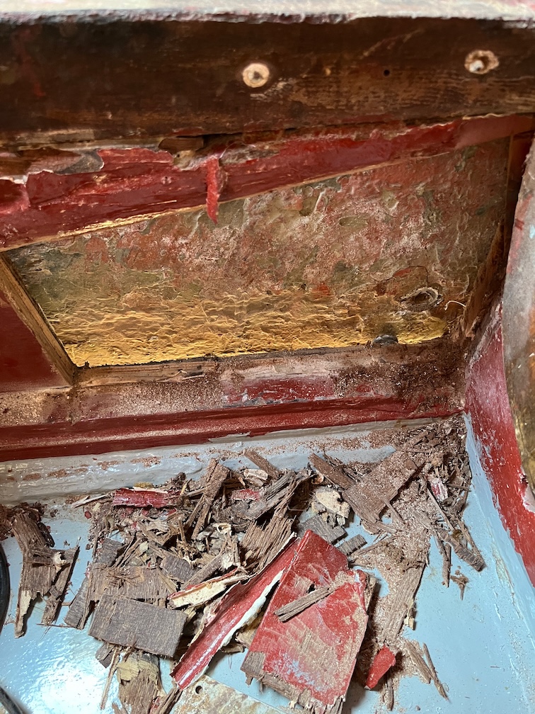
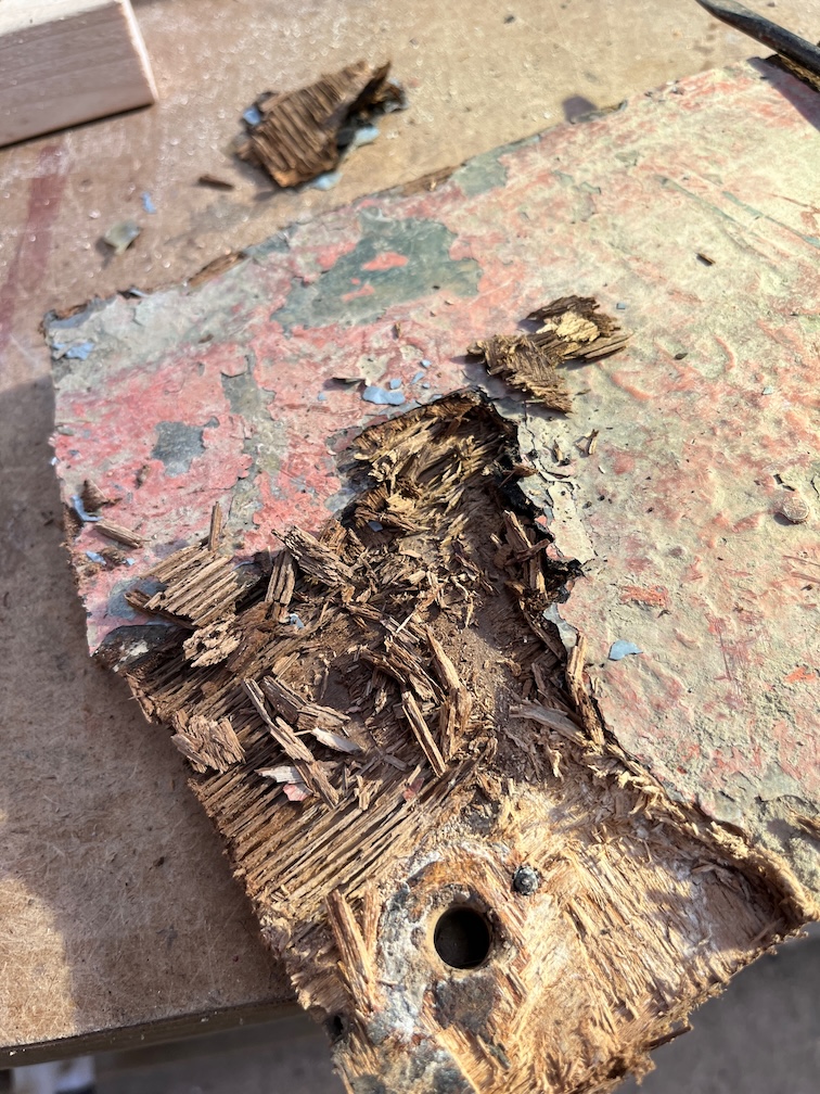
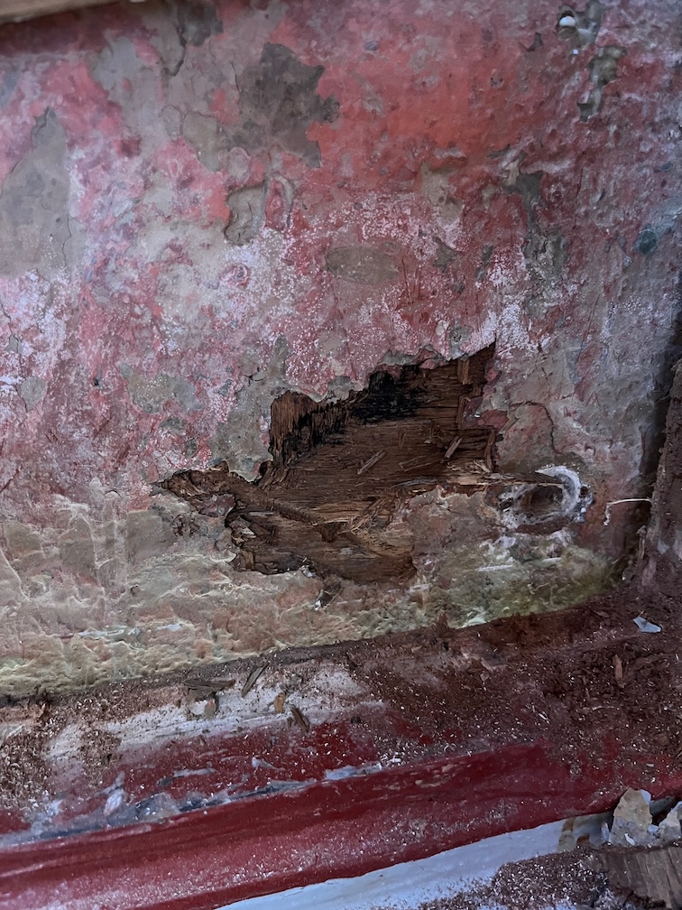
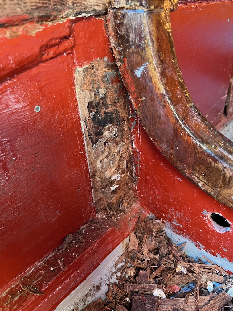
Back in the workshop I took a closer look at the section of the case that I had just cut out. It is in very poor shape as you can see. This large flake of wood came off just using my fingers.
And this was cause by scraping the wood with a screwdriver. It’s totally rotten. The inner face of the case seems to have been coated with something, presumably to stop the steel plate from damaging the wood, but under that it is soft and fragile.
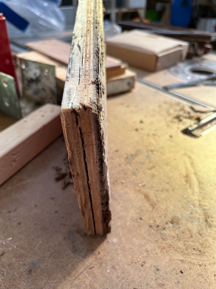
Looking at the end of the cut piece you can see the plywood that Tony glued to the outside of the case to reinforce it. This split away from the original casing when I prised the section out. Then there is a fairly intact middle layer of plywood and then the darker part that is the rotted plywood. It looks as though the sides of the case were made from two piece of plywood glued together with something like Aerolite glue and the inner face of the case covered with something, perhaps Aerolite glue again, as protection. Over the years the rot has gotten into the inner layer of plywood but has not been able to cross the glue barrier into the original outer layer of plywood except where close to the pivot bolt hole.
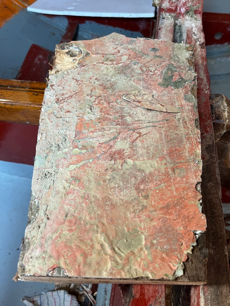
As a final task for today I took a screwdriver to the other side of the case and as you can see form the above photo, it too is severely compromised. The conclusion I draw from examination of the casing is that the rot has spread at least as far as the solid ends and will therefore need to be completely removed and replaced with a new case.
Now that I have the side of the case opened up I can see that this isn’t going to be such a difficult job as I had first thought. I will have to cut away the two side reinforcing bulkheads, which is mildly annoying but has to be done, before cutting the case as close to the keel as possible. The idea being that if I’m careful with the removal I should be able to use the removed case as a pattern for the new one.
We shall see.
I’m fairly confident, however, that if Tony Smith had not reinforced the case when he did then Shoal Waters would have sunk, either on her mooring or, more likely, when being sailed and the leverage of the water on the centerplate on the case cracked the case apart. Scary to think about.
Still, a new case made from high quality marine plywood from Robbins Timber will put her back into sailing condition for many years to come.
Time to start work on figuring out why the case is leaking and why the surveyor had concerns about the integrity of the wooden casing. This is what he wrote in his report, a copy of which I have been given:
On examination of the casing, there is no indication of leakage through into the bilge compartments of the vessel, all areas are seen well painted, dry and clean. The casing is found generally well fitted still and without obvious movement. There are no areas of soft timber that can be fully determined without further opening up.
However, soundings of the plywood cladding gave dull returns which are indicative of degraded timber that might exist within the original casing boards; beyond the thickness of the added plywood cladding.
We had already been advised by Tony Smith that there is a leak in the region of the centreboard case, it is just not obvious.
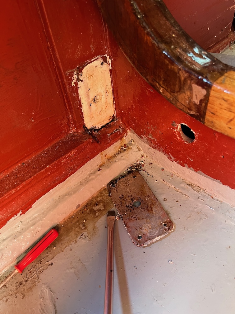
The first place to start is the removal of the two metal plates through which the pivot bolt passes. These are held in place by what turned out to be stainless steel screws which came out easily.
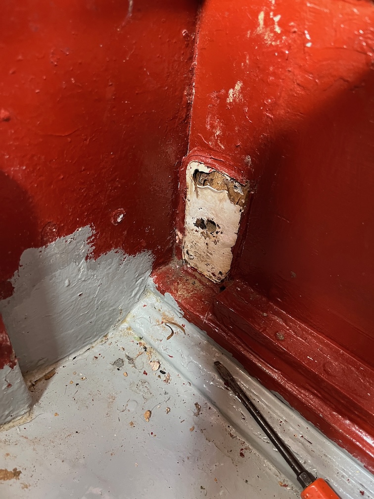
The plate itself had to be prised off and underneath the plate was a white sealant.
The same was found for the other side of the case. The wood under the sealant came off in layers like you would expect of plywood, except it seemed to be solid mahogany or similar. It did not come off easily and had to be removed with a chisel.
And that makes quite a mess !
I decided to take another look at what prevented the centreplate from being removed from under the hull by putting my camera on the case looking down through the slot. This is the result:
So, I had briefly entertained the notion that the issue with the case could be easily located and solved, but now that I’ve seen this obstruction more closely and noted the fact that it seems to have made a gauge on the inside of the case, I have not choice but to remove the starboard side of the case so that I can access this damage, asses and repair it.
If the damage was caused by the centerplate removal then I would not have expected so much damage to be caused unless, as I mention in the video, the wood was already soft i that area or possibly rotten.
I’ll cut away a section of the timber in that area, perhaps a foot wide and from the bottom of the case to the top of the side panel. This will give me a large enough area to see how far down the damage goes and will also allow me to examine the wood on the other side of the slot.
I’ll make the cut as carefully as possible in such a way that the replacement isn’t going to be an odd shape. Or no more odd than is normal for a boat, but that’s a task for another day.