
While I wait for the spacers for the charge controller and switch box to be varnished, I can work on the front panel of the switch box.
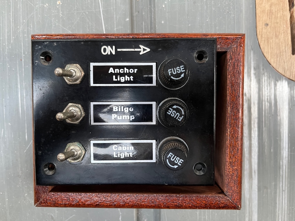
With the walls of the box now much thinner, the existing front panel is too small to fit the new hole. The obvious answer to this is to make an auxiliary front panel to fit the gap. Armed with the box, switch panel, calibers and a CAD program I designed said front panel that I initially cut out of 3mm plywood on the laser cutter.
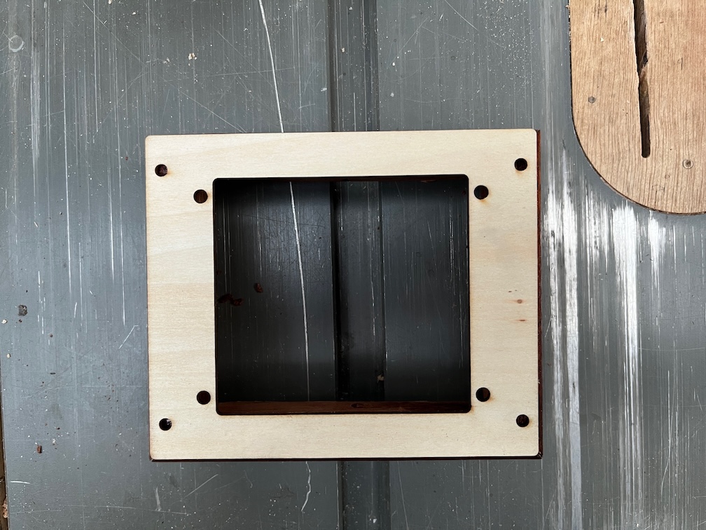
This is the result. It took four tries to get it exactly correct but that is what prototyping is for.
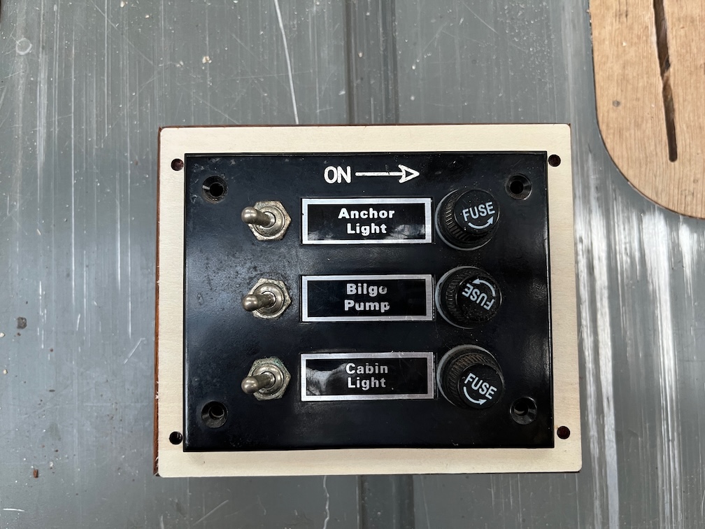
The new panel will be bolted to the switch panel and screwed to the box. Once I was certain the dimensions were correct I cut the final version from 3mm acrylic sheet.
This came out well and looks very professional. The advantage of having the right tools for the job.
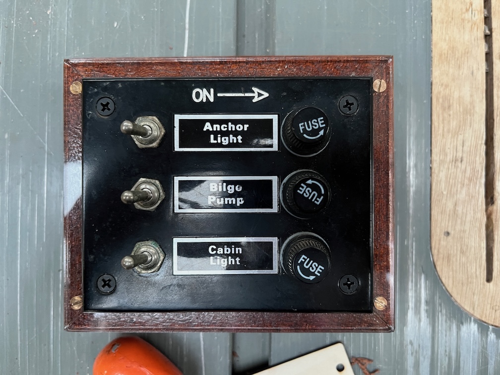
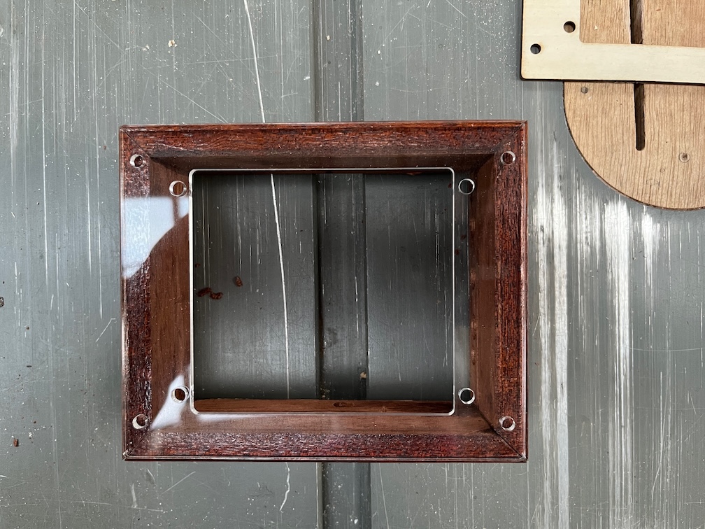
The result is pretty good looking, the black bolts merge into the black of the switch panel and the acrylic allows the wood to show through. The drawback is that you have to remember that the bronze screws are the ones to undo when opening the panel, not the black ones.
Not that the black ones will unscrew since they are bolts with self-locking nuts on the inside. Any attempt to open the panel using those will just result in the bolt endlessly turning.
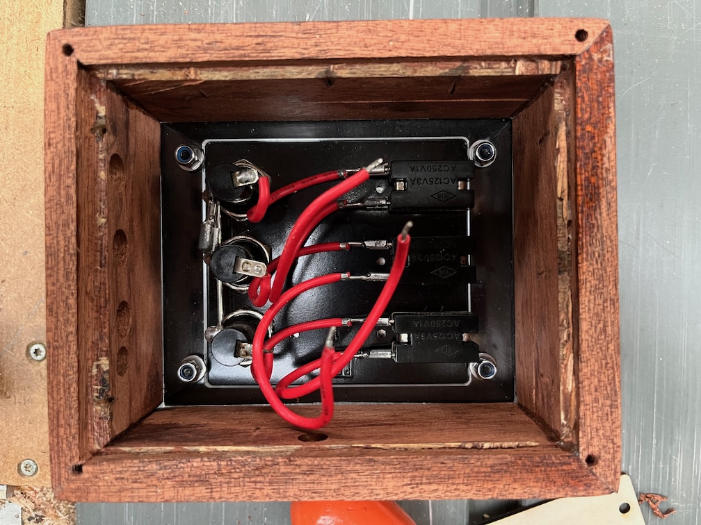
One of the things I will do before fitting the switch box to the upstand is to cover the exposed connections with heat-shrink sleeving so that none of the connections may be accidentally connected to another wire, such as dropping a screw in the box, although I hope that I’d remember to disconnect the battery before doing anything like that, but I could see a reason to do this if I were using a multimeter to check the voltages on the wires.
The heat shrink sleeving could be considered to be excessive, but I just do not like seeing all those exposed connections. A job for tomorrow, I think.
For now…
Time for a cup of tea.