2026-02-09 – Galley Stove III

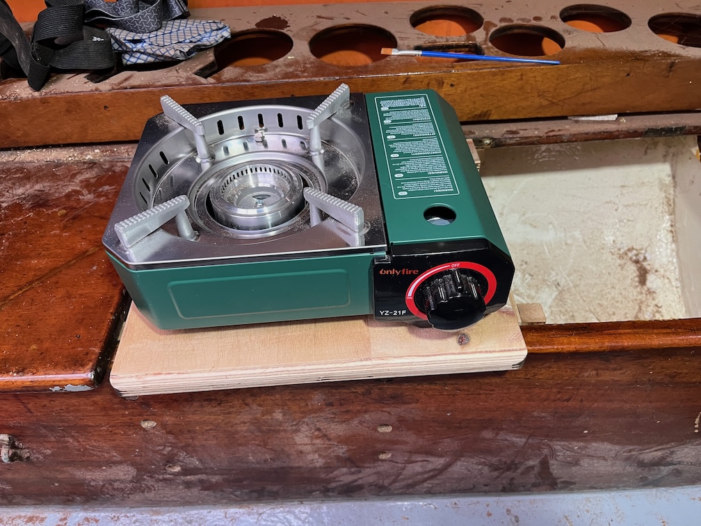
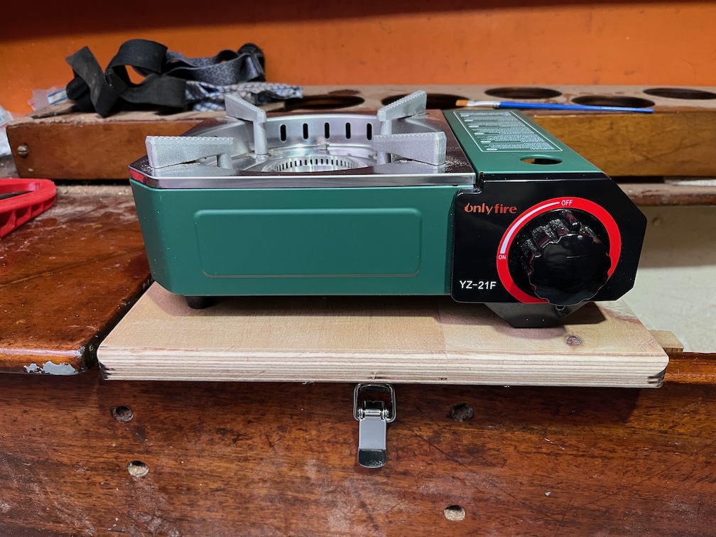
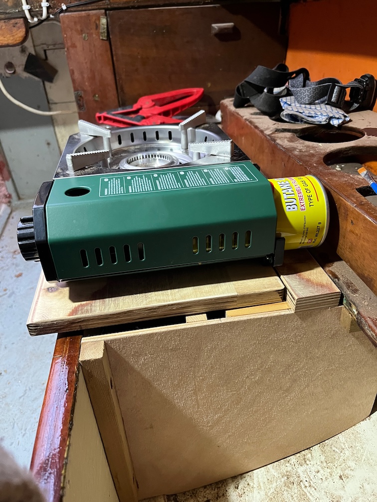
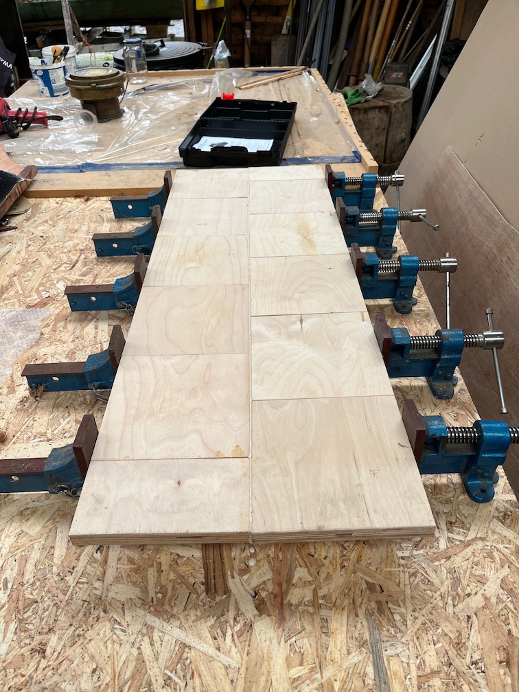
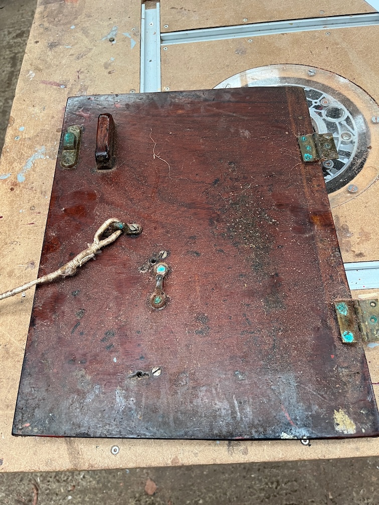
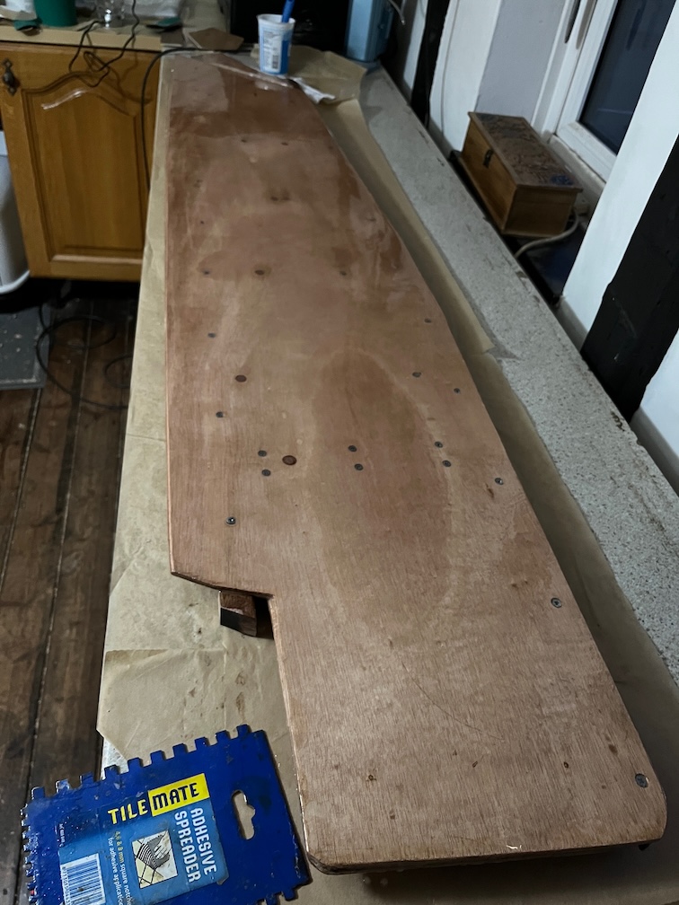
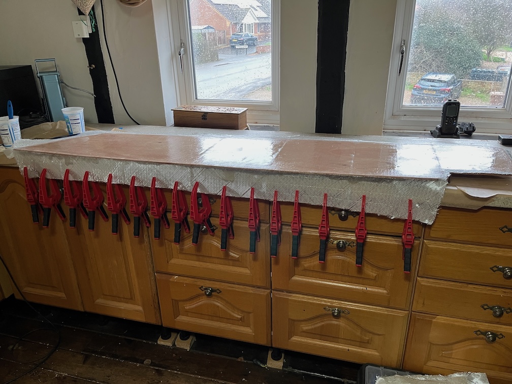
Today, being a work day, means that I carried out small tasks that could be done during a teak break or before breakfast. First up was the galley stove locker lid which is basically a copy of the board upon which that stove is mounted but without the stove.

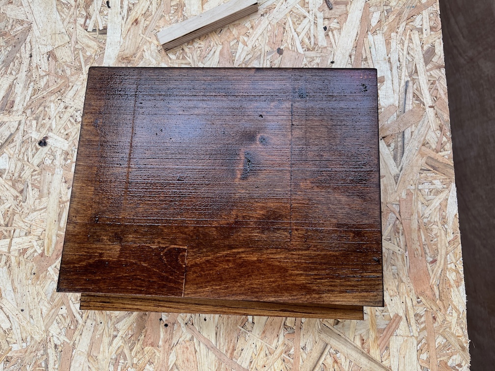
Very easy to make there’s no glueing or awkward bits and the result here has a coat of stain on both sides. I’m using some trapezoidal standoffs to keep of off the work surface.

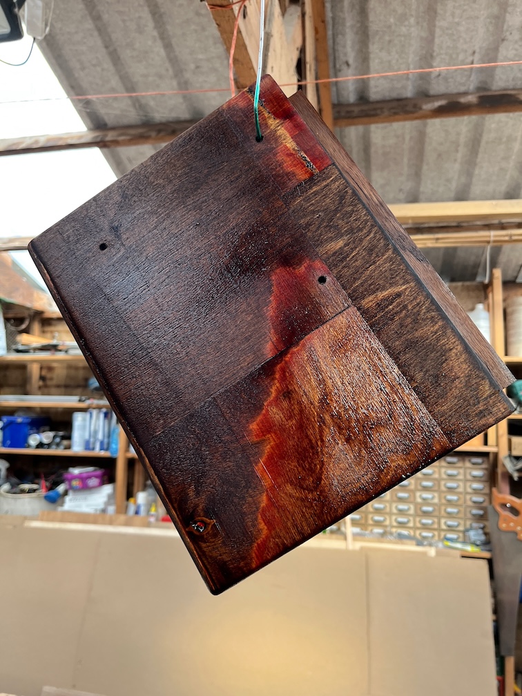
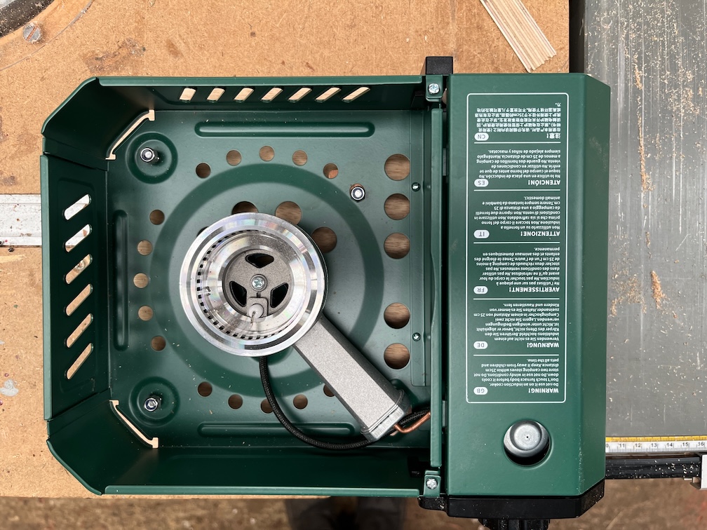
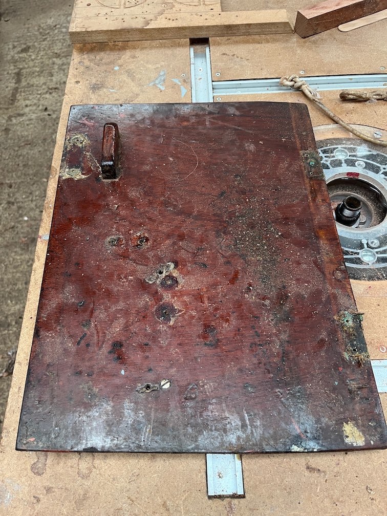
Whereas the stove base board, which has holes, is hanging from a string in the rafters and now has two coats of stain. Once both have two coats of stain and are dry they will be varnished with a few coats before being ticked off the to do list.

Time for a cup of tea.

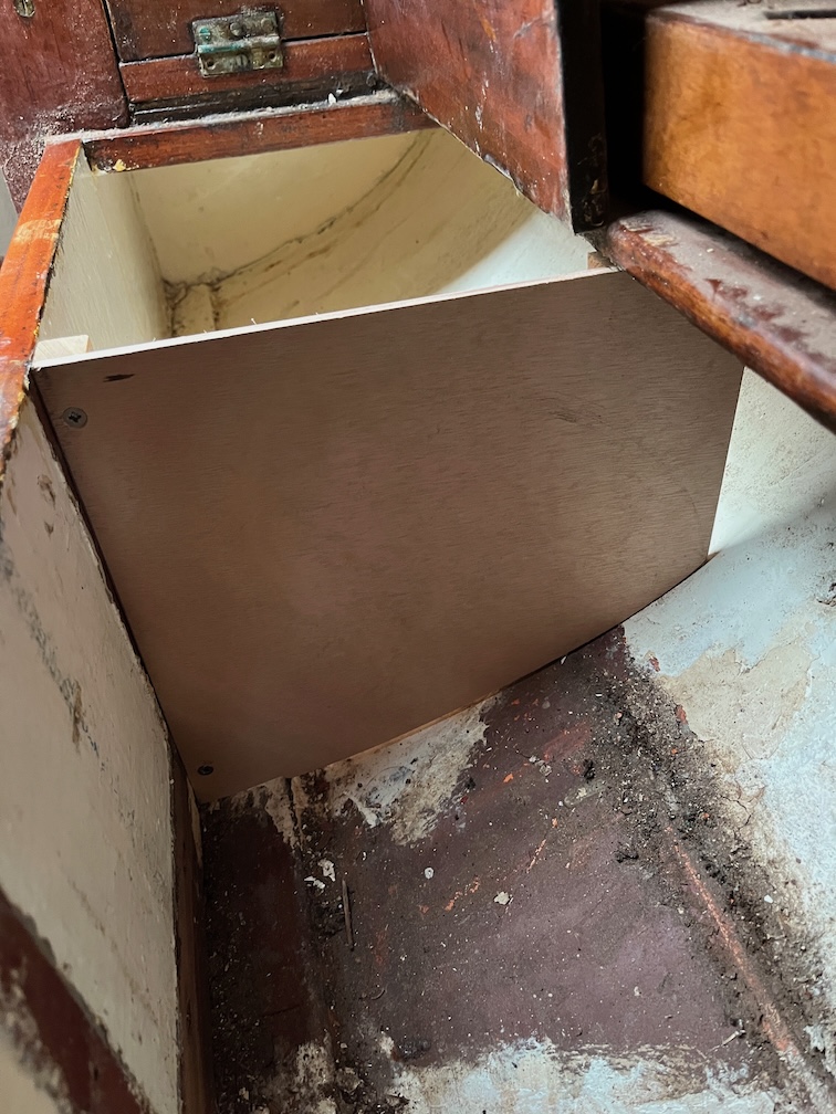
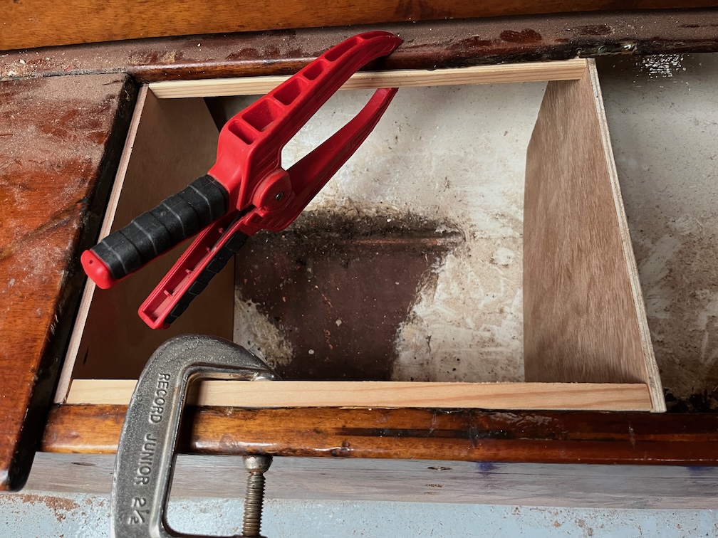
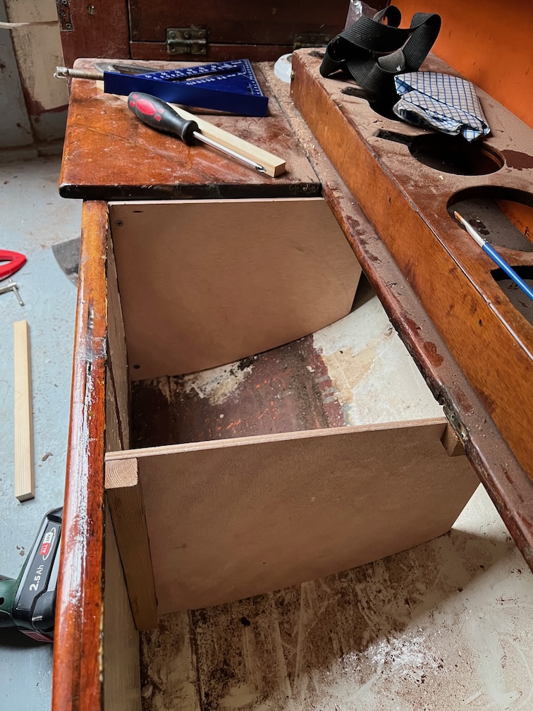
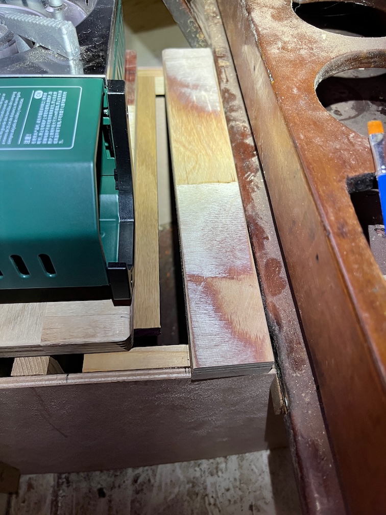
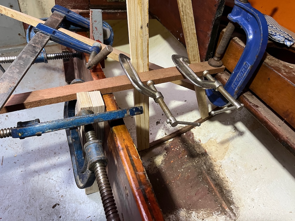
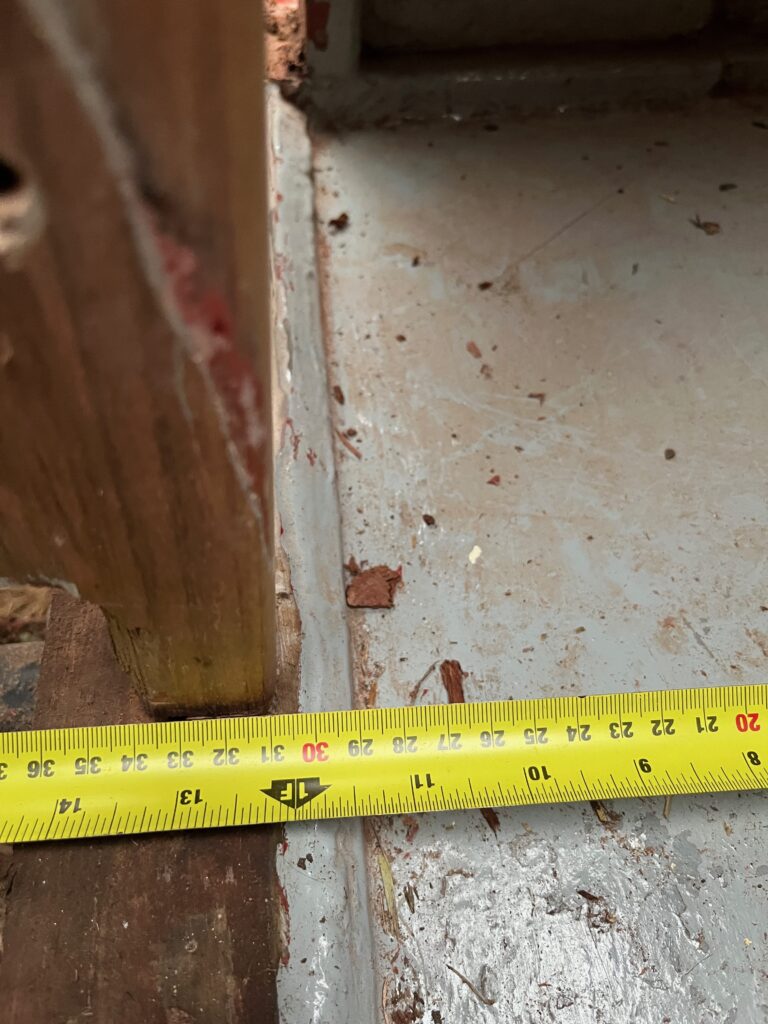
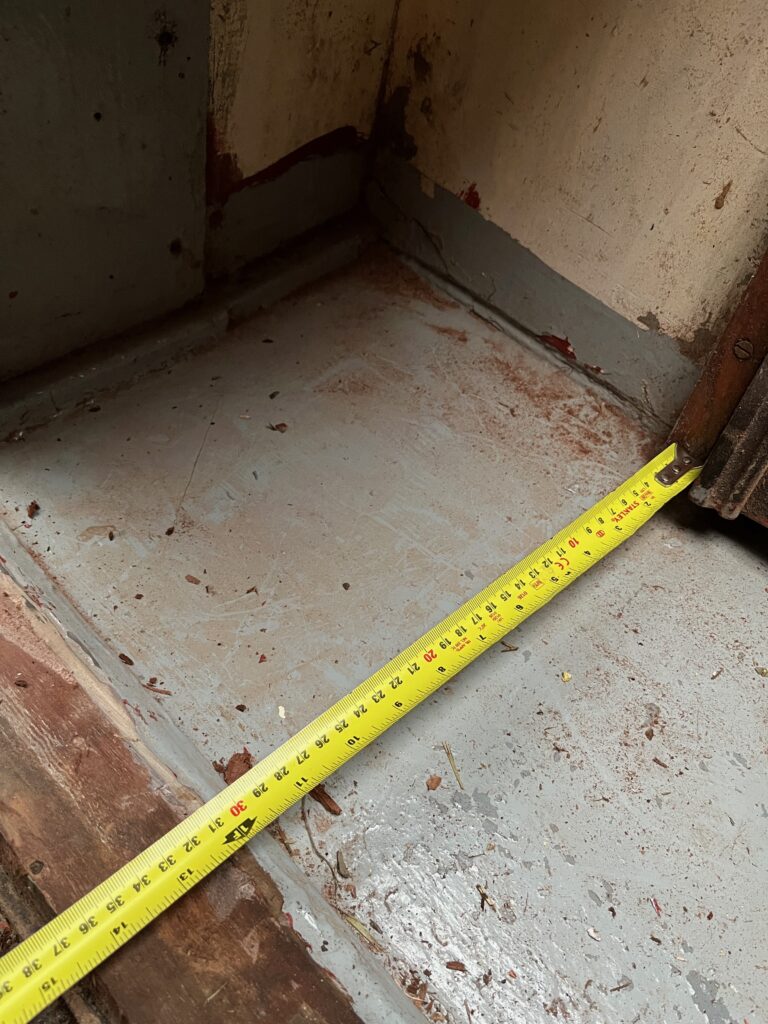
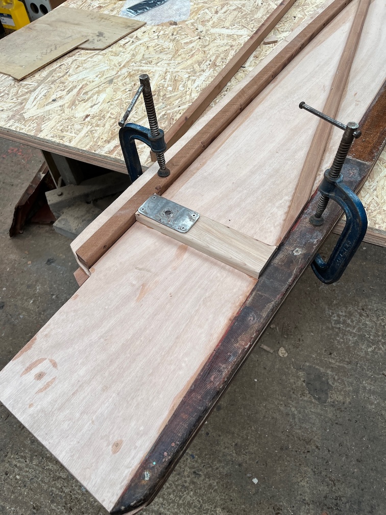
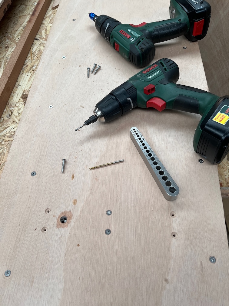
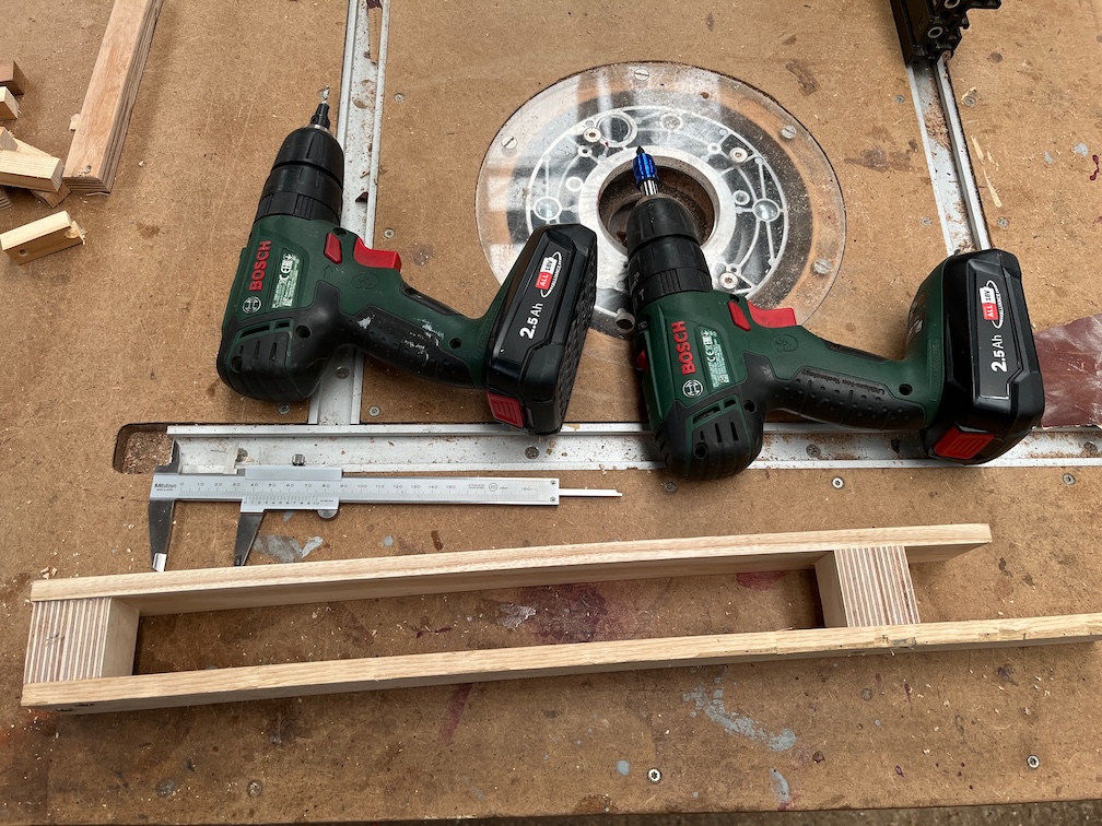
The next task on the list was to make a saw jig for the aft case bock so that the rotten/soft section could be sawn off by hand with as smooth and flat a cut as possible. The problem is that the space was sufficiently restricted so as to prevent the use of either a circular saw or a jigsaw, or at least the ones I own, and also all my hand saws with the exception of the pull saw. This blade is very flexible and to get an accurate, flat cut in such a tight space required a jig.

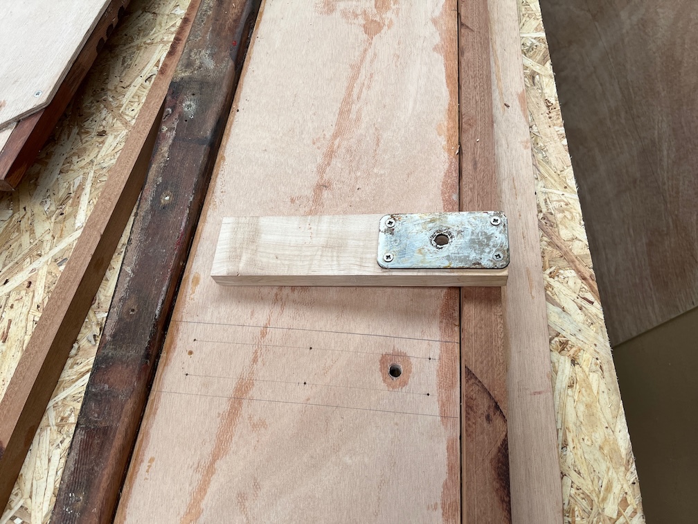
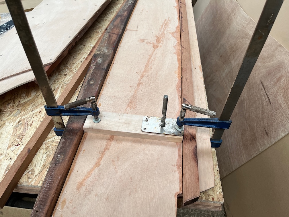
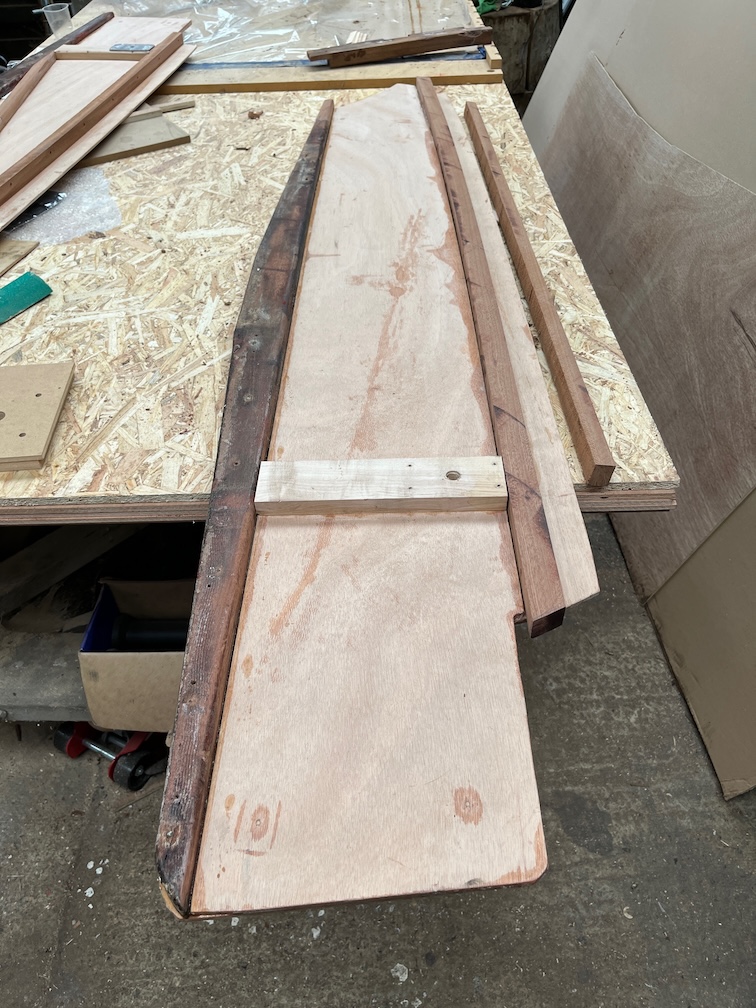
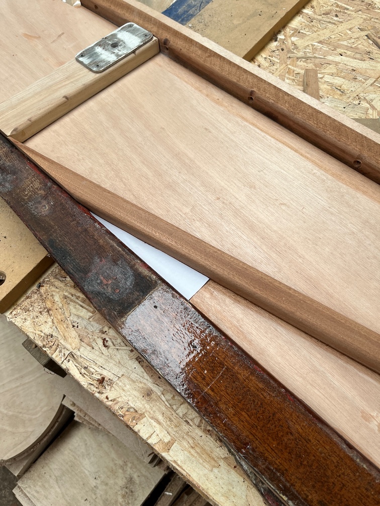
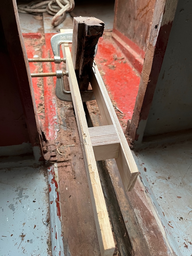
Essentially, I clamped two identical battens either side of the block and fitted two spacer blocks at either end. These held the two battens apart the same width as the width of the block. I made sure that the battens were parallel, straight and screwed them to the blocks such that they formed a rigid structure. This jig was placed over the block such that the upper edges of the battens was at the correct place for the cut and the jig clamped securely in place.

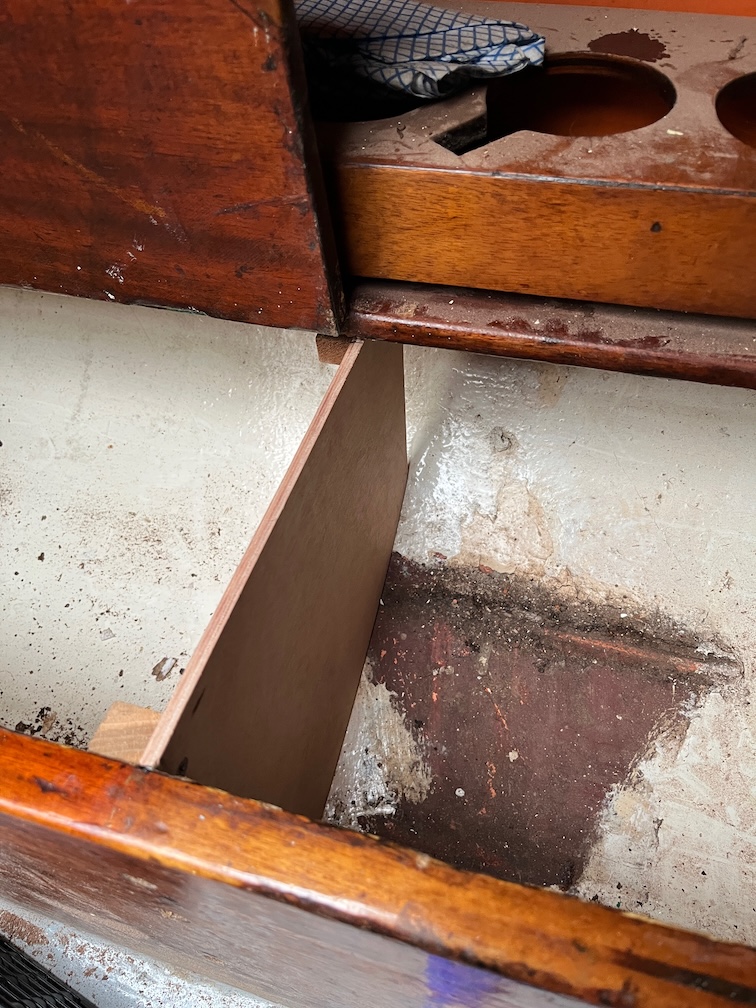
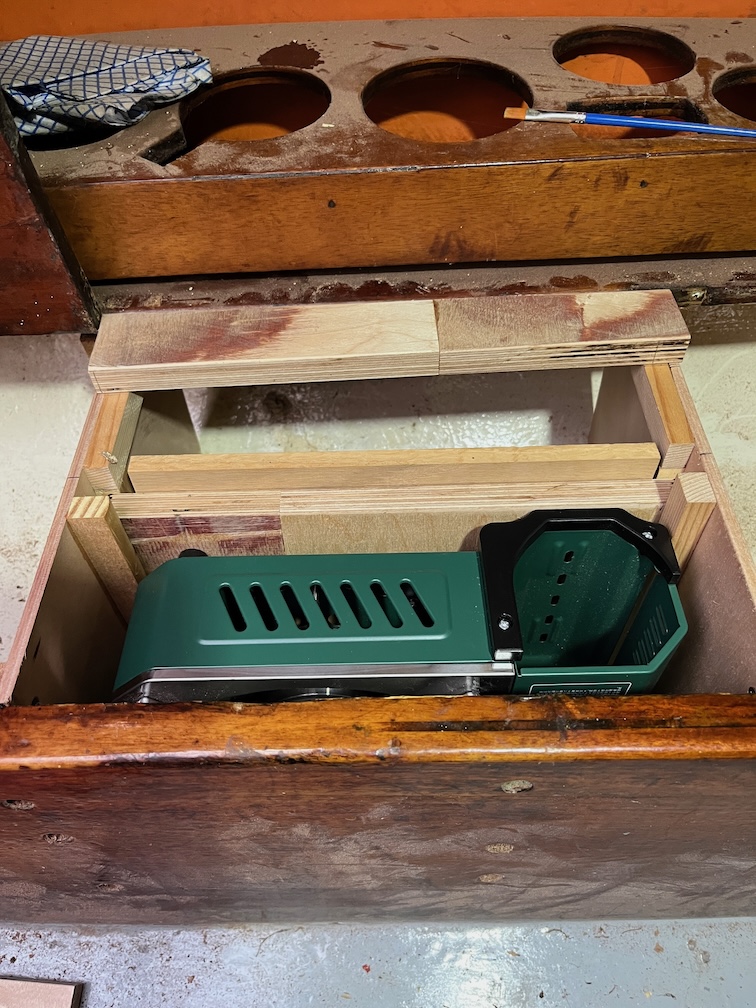
Now the pull saw had two guides, one on either side of the block and I could carefully cut off the top.

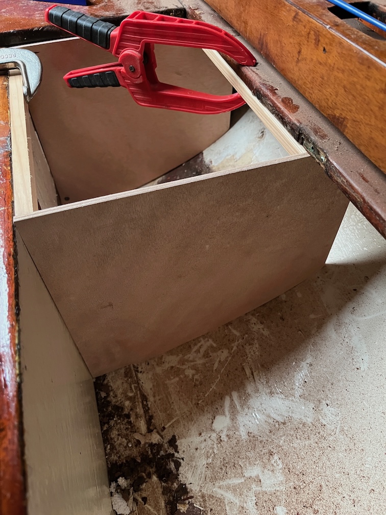
I had to use the saw from the inside as the cockpit was too narrow for the saw.

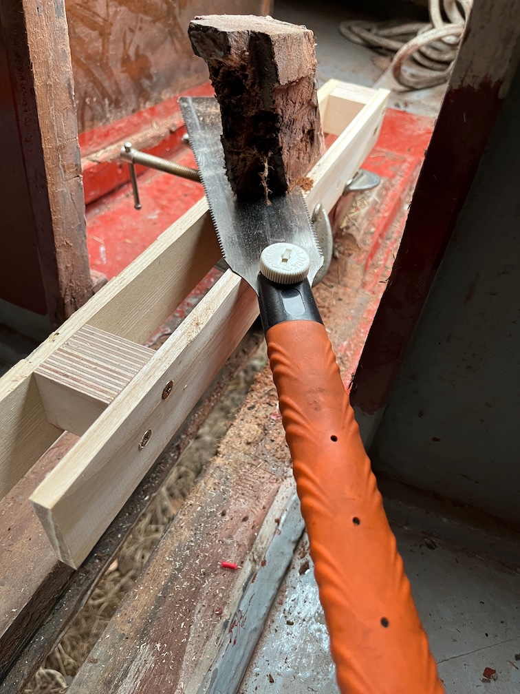
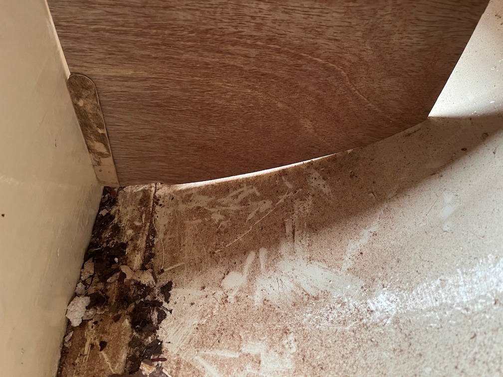
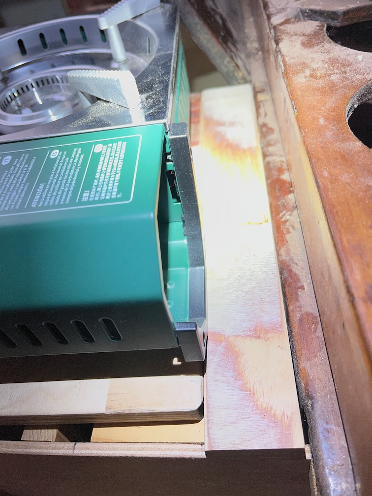
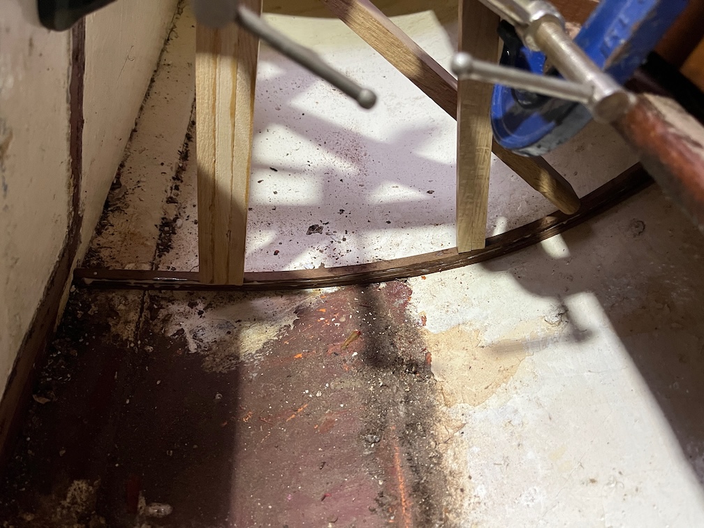
But here you can see the saw in action and also the function of the saw jig which, I have to say, worked better than I expected.

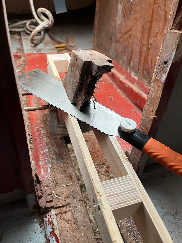
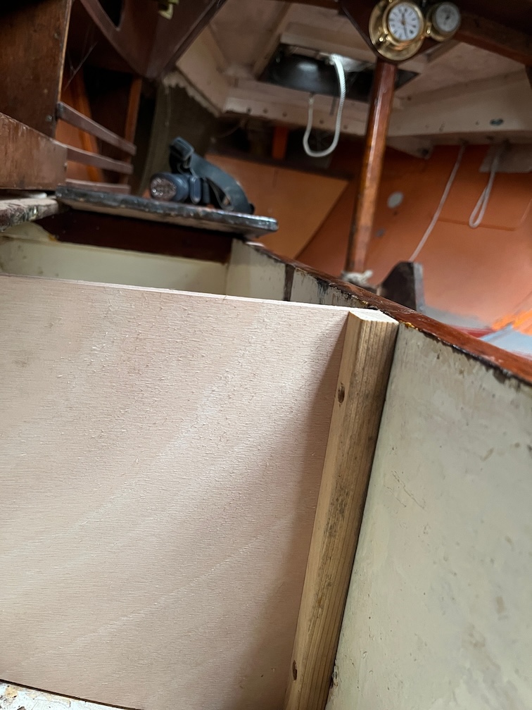
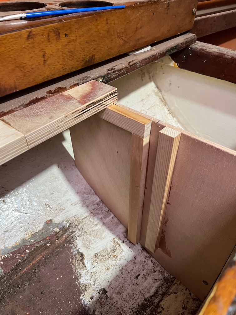
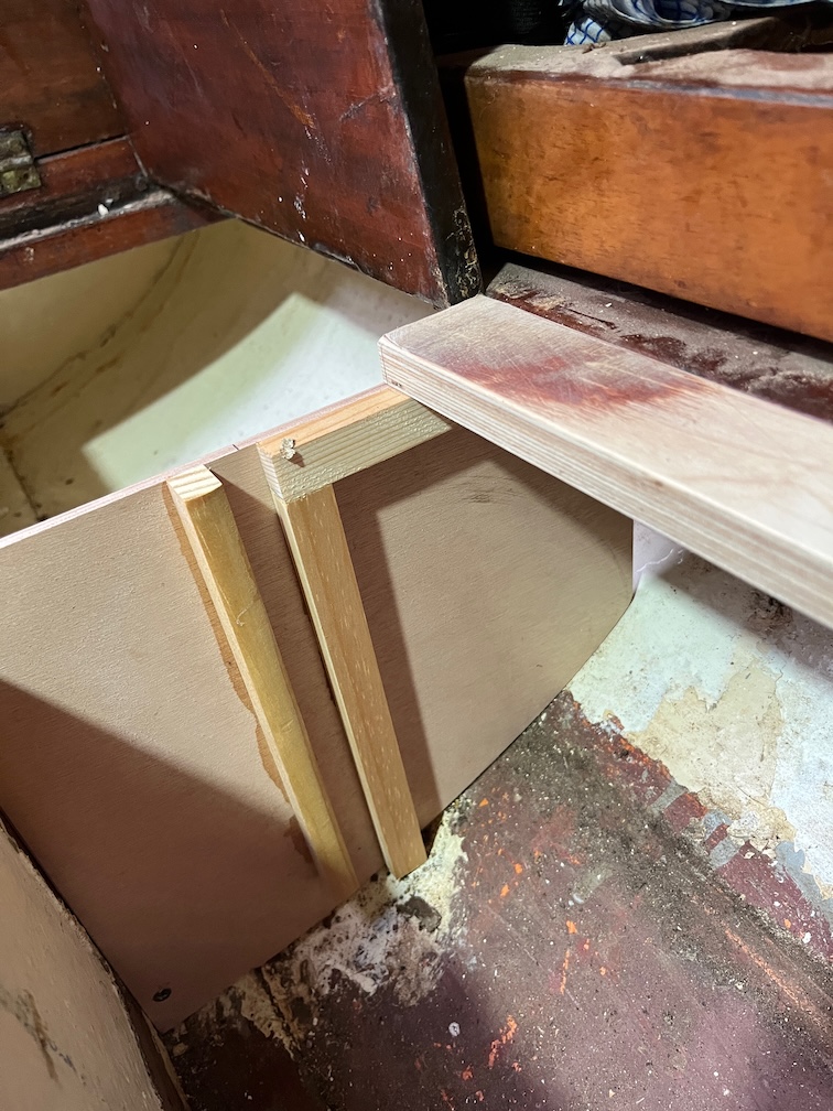
A slightly different angle on the cut.

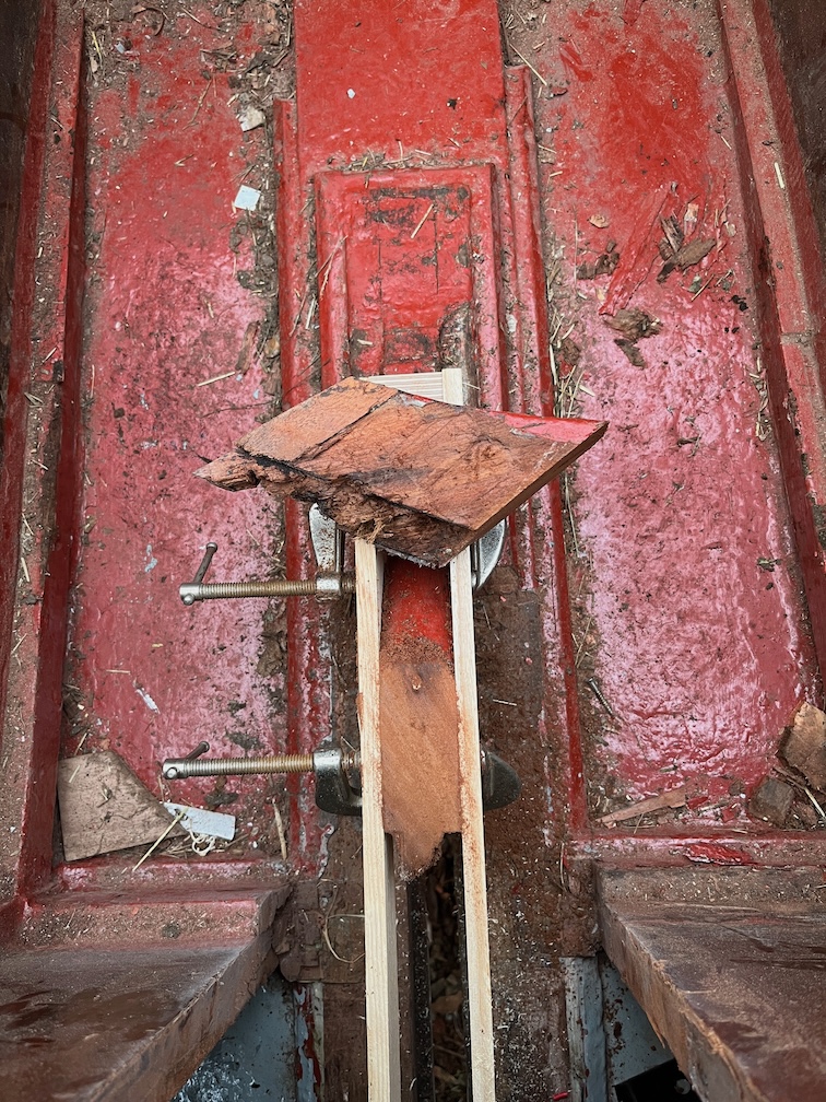
This shows just how well the jig worked, the cut is clean and flat.

Of course, it took longer to carry out than it did to describe it !

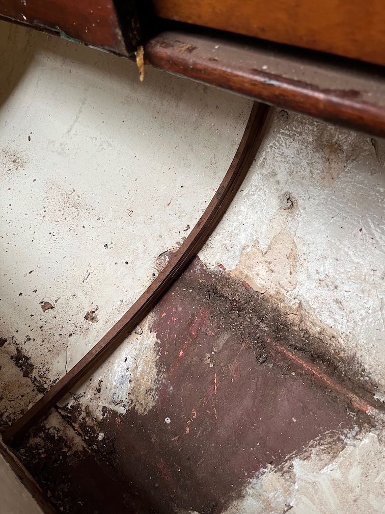
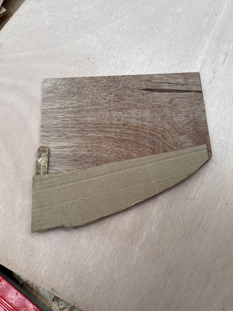
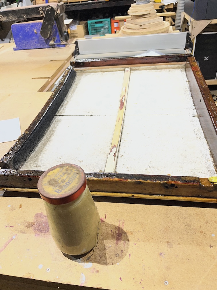
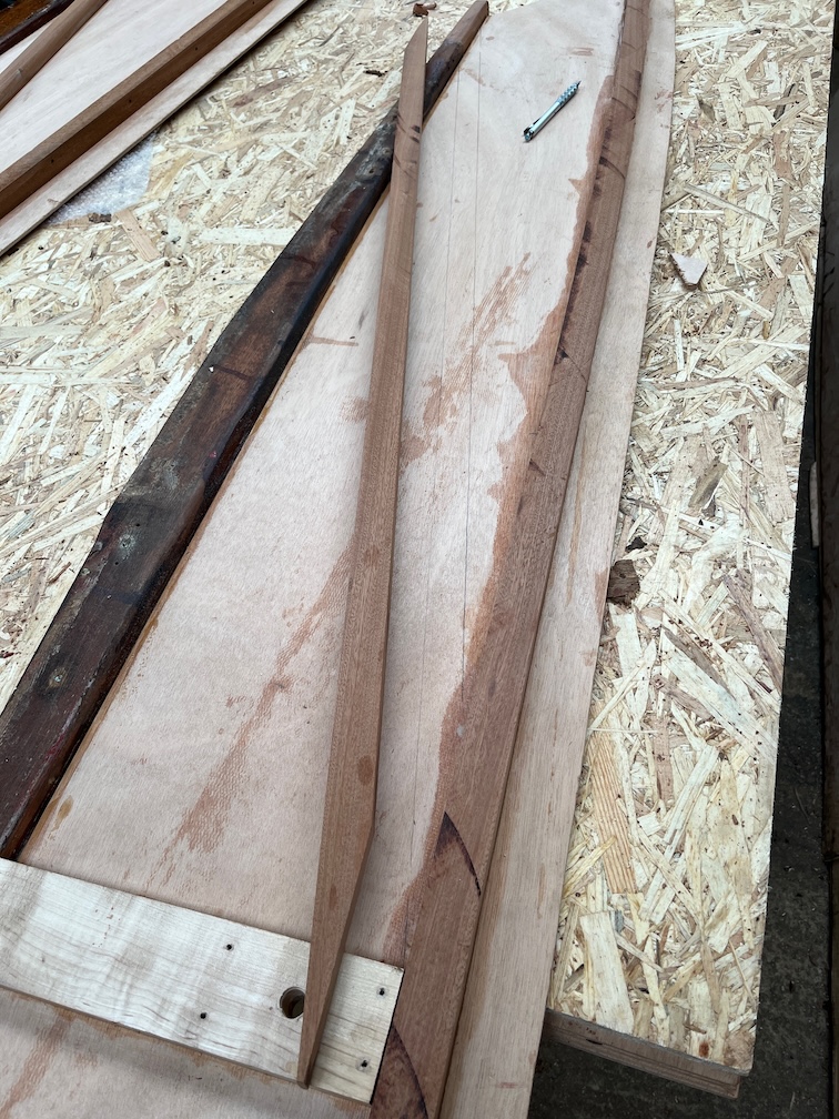
Back in the workshop I could take a look at the offcut. Like this it is not that informative.

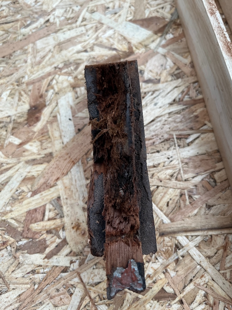
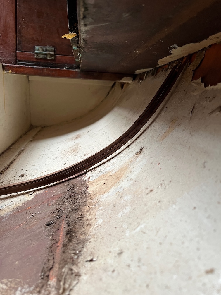
This shows more clearly the problem.

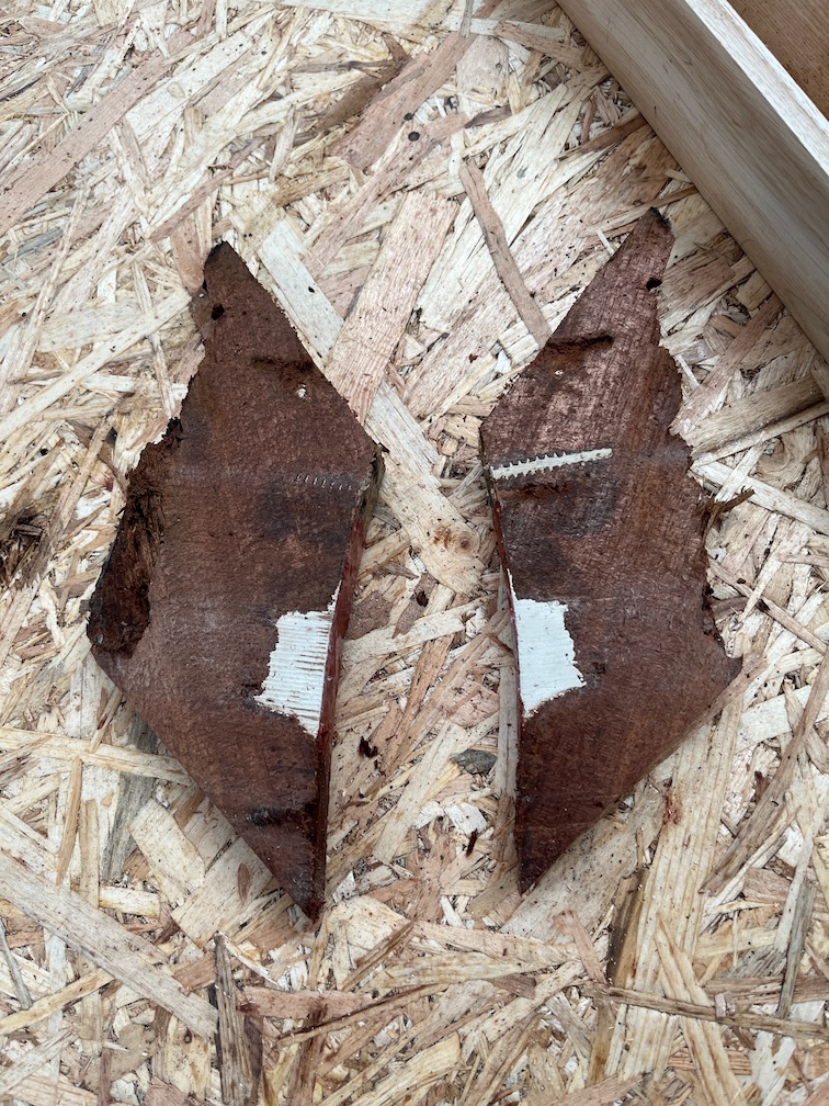
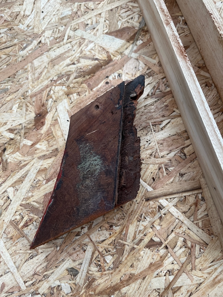
I had to cut the piece in half lengthways because I need the shape to make a new piece and with rounded edges on the outside, this would have been difficult. However, cutting it in half did give me some more insight into the issue.

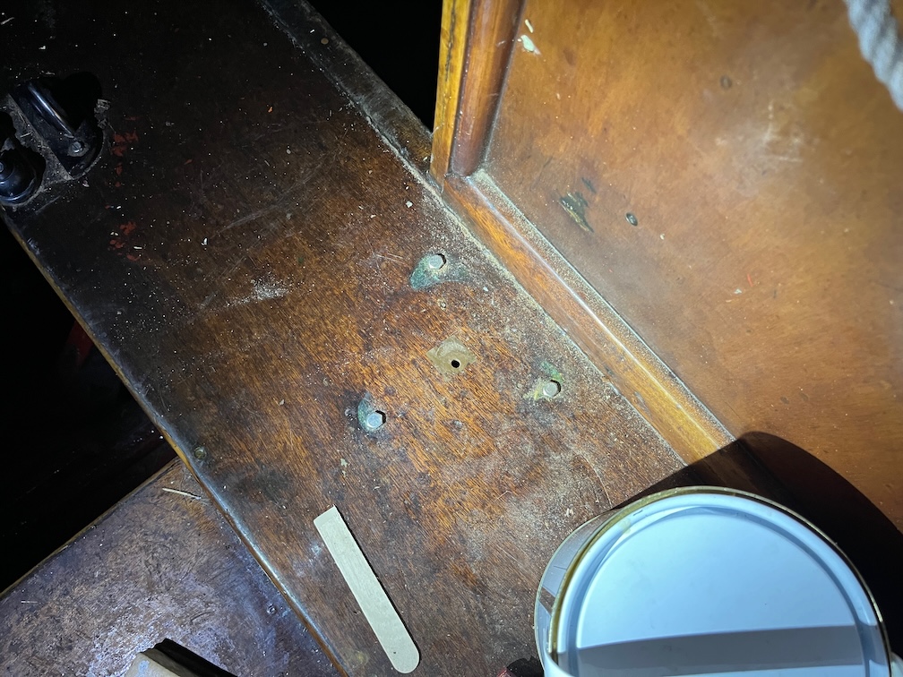
The soft, and possibly rotten, part doesn’t really extend into the body of the offcut except in one place. There are two holes that have been filled with some kind of filler, one a screw hole and the other a larger void for something.

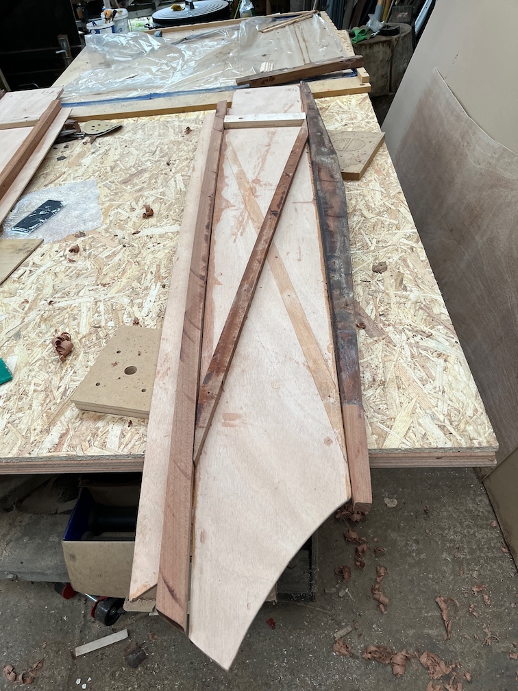
Here’s the interesting thing. Poking around the soft area I found that the really obvious soft wood was joined to the larger of the filled in sections. I’ve marked that soft section in white. The inner surfaces of the centerplate case were coated with a waterproof glue, including the fore and aft blocks, so unless the glue layer was damaged then the softness was unlikely to start from the inside, especially since that part of the block is above the waterline most of the time.

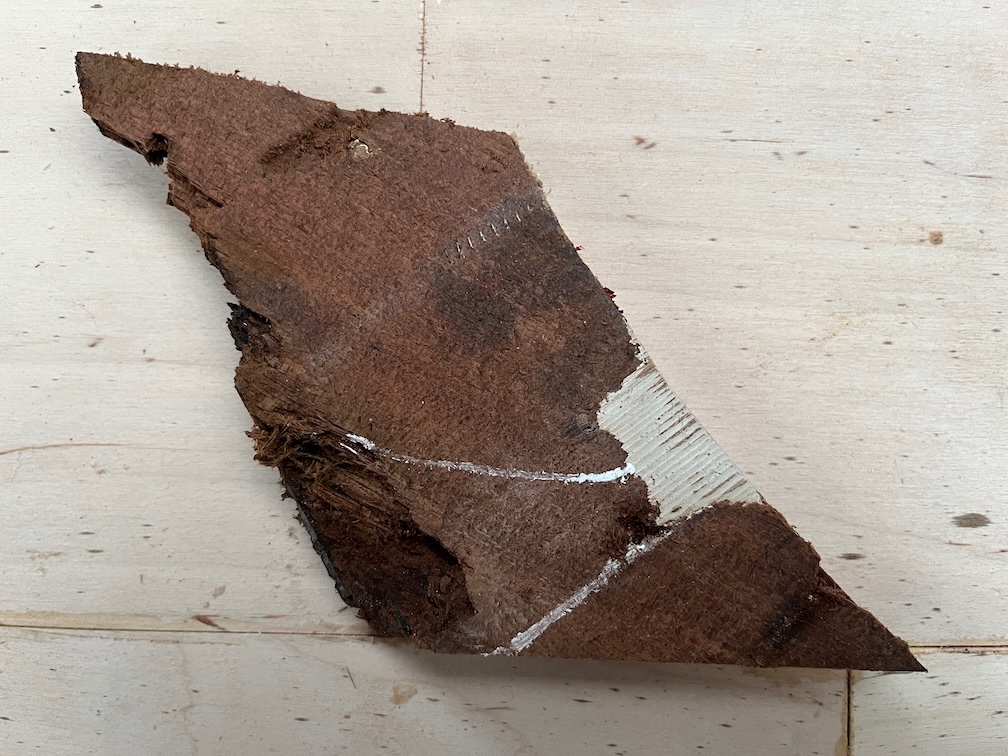
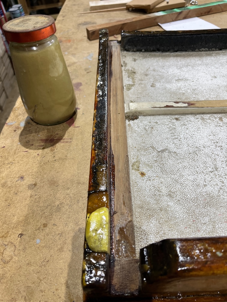
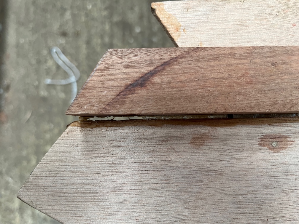
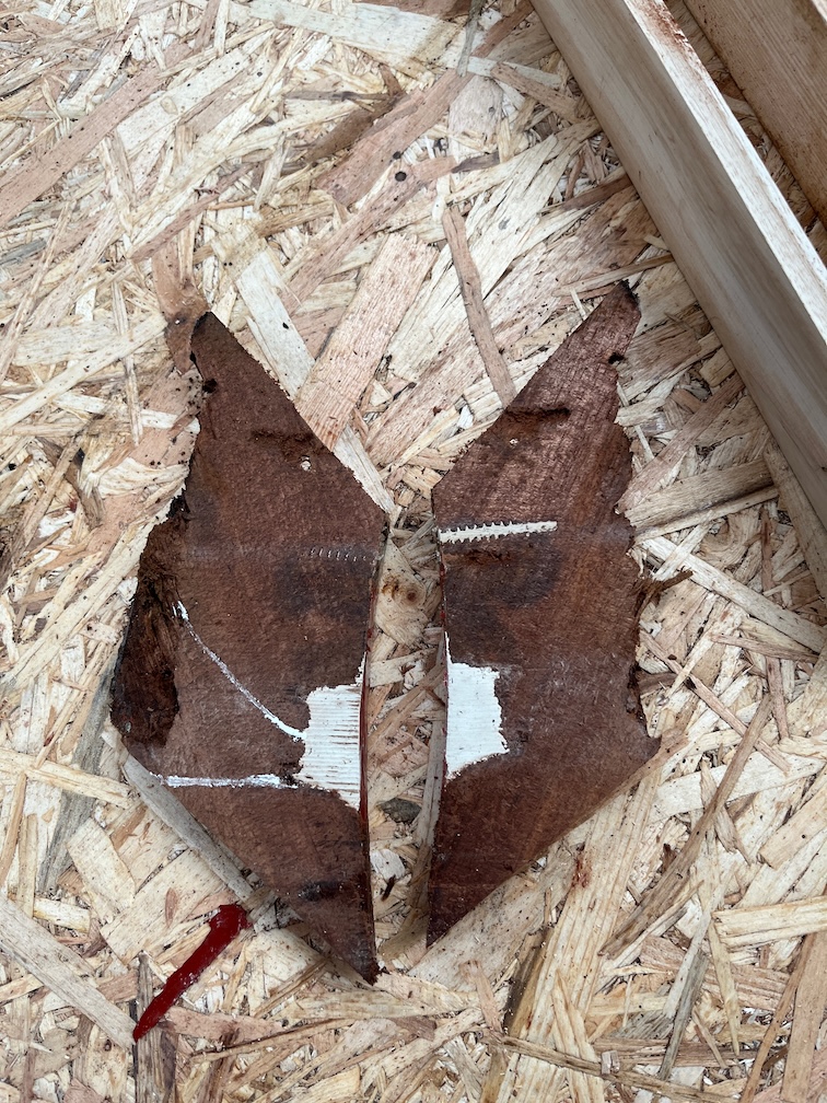
If I rotate the piece so that it is shown as it would be in the boat, you can see that the large filled void slopes downwards and the soft wood goes to the bottom part. You can see where I picked out some of the soft wood with my fingernails. So, one possibility is that this void was left open for some time and both fresh and salt water was allowed to pool in the bottom eventually causing the wood to become soft.

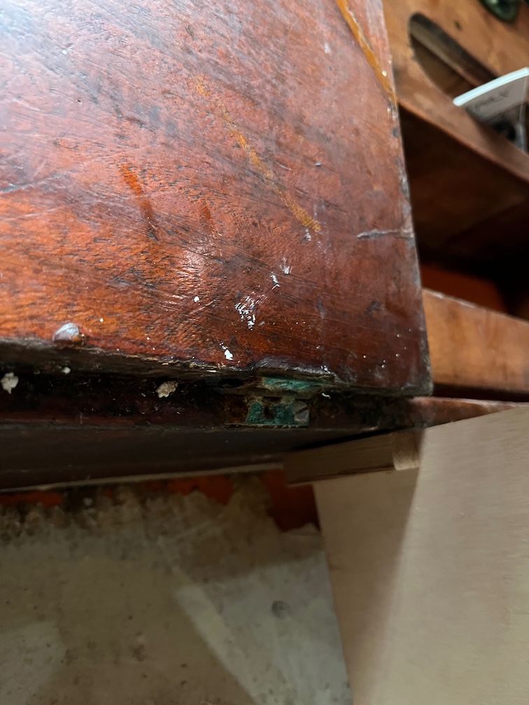
In the above photo you can also see a lighter area from the pointy end of the screw hole diagonally down to the edge of the block. This is also a bit soft and the same thing may have happened here.

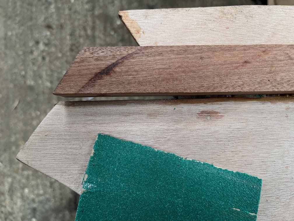
I have highlighted the bit I’m referring to in green.

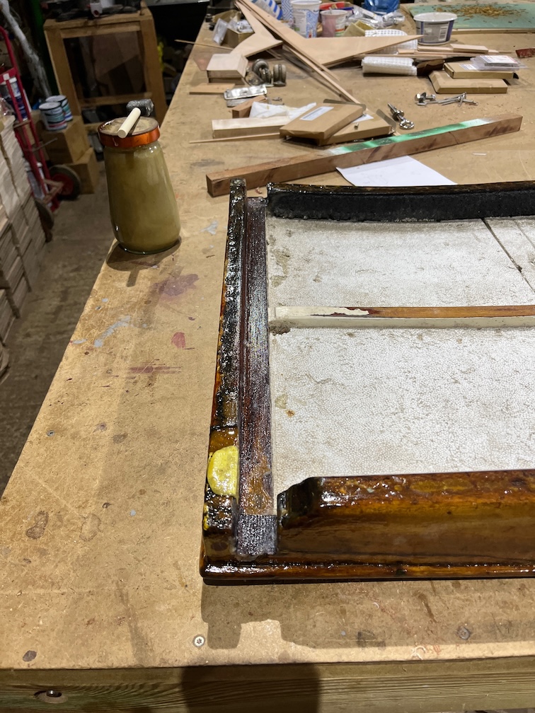
Nevertheless, my cut was nearly perfect, just below the extent of the soft wood. Making a new piece to replace this should be fairly easy and the next tasks in the never ending saga of the centerplate repair !

Well, it seems like it.

Time for a cup of tea.

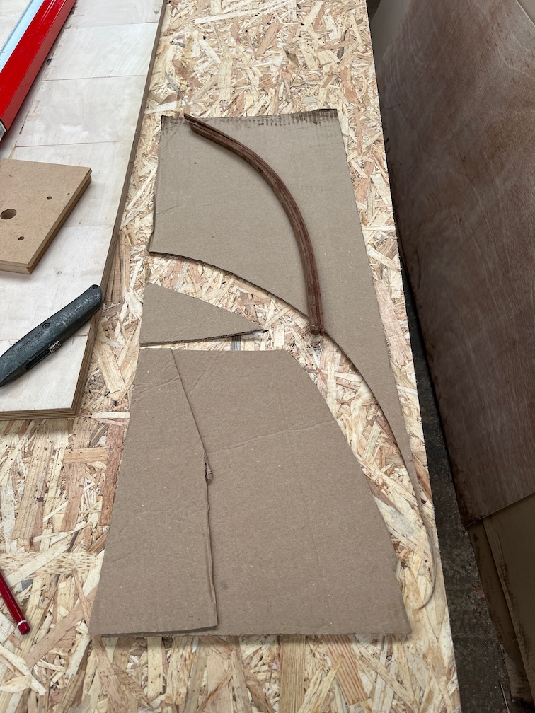
The next task is to make the new aft block section and for this I’ll need a template.

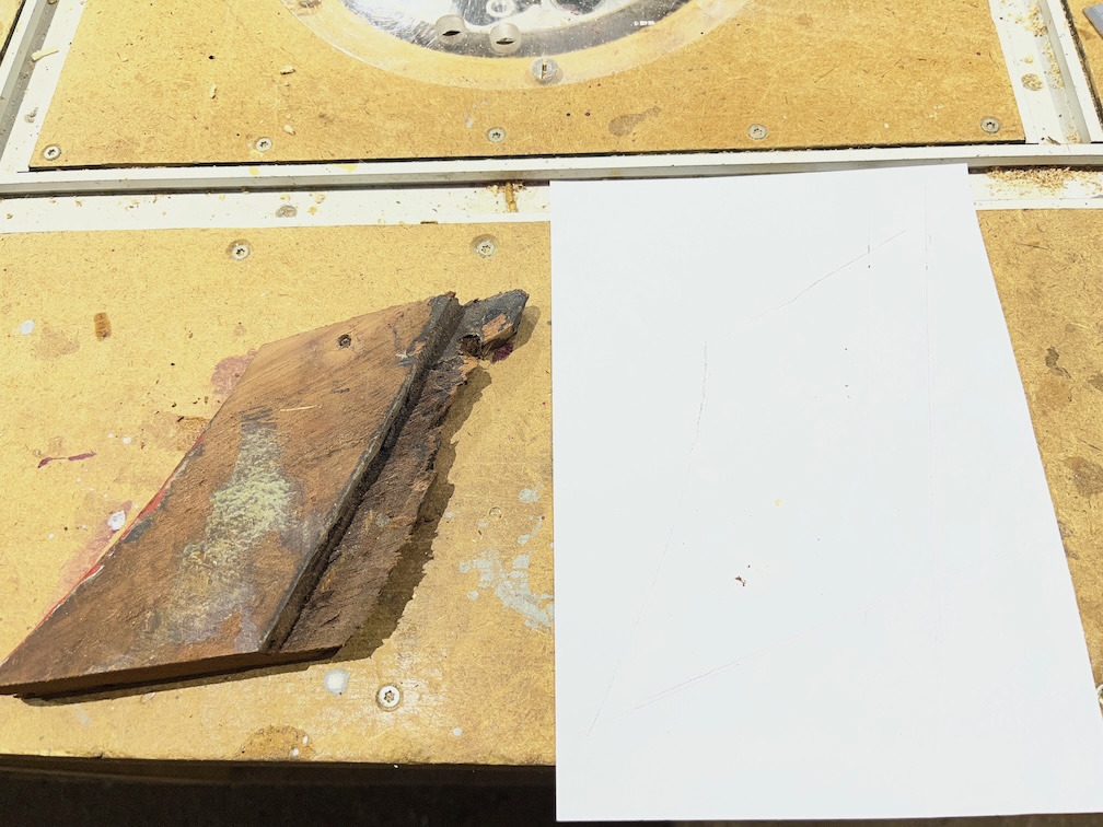
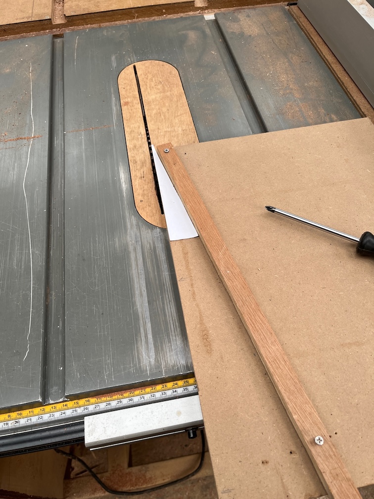
Firstly, I drew the outline on a piece of paper. Not easy to see the faint pencil lines, but they are there. The template is about 1 mm taller than the cut piece to allow for the saw cut.

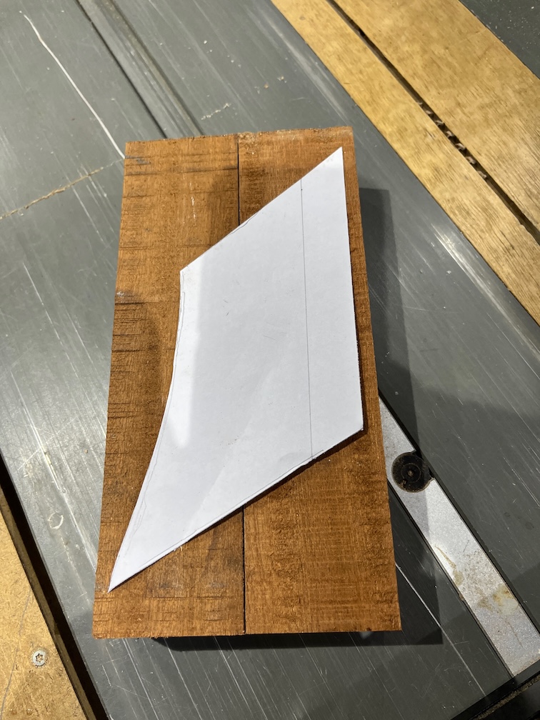
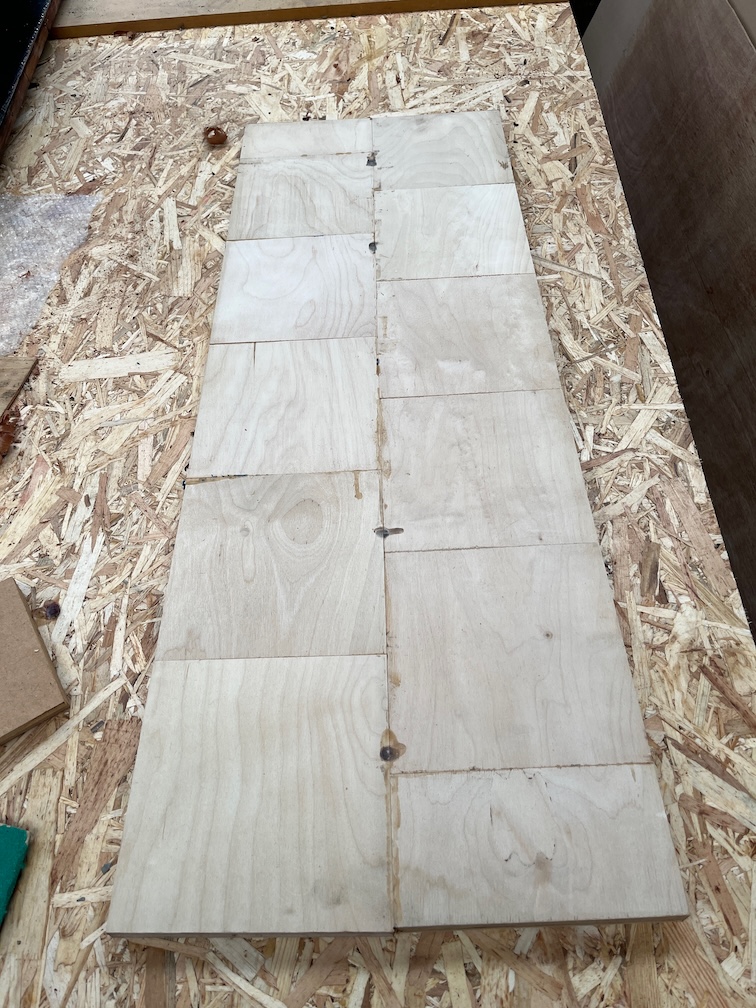
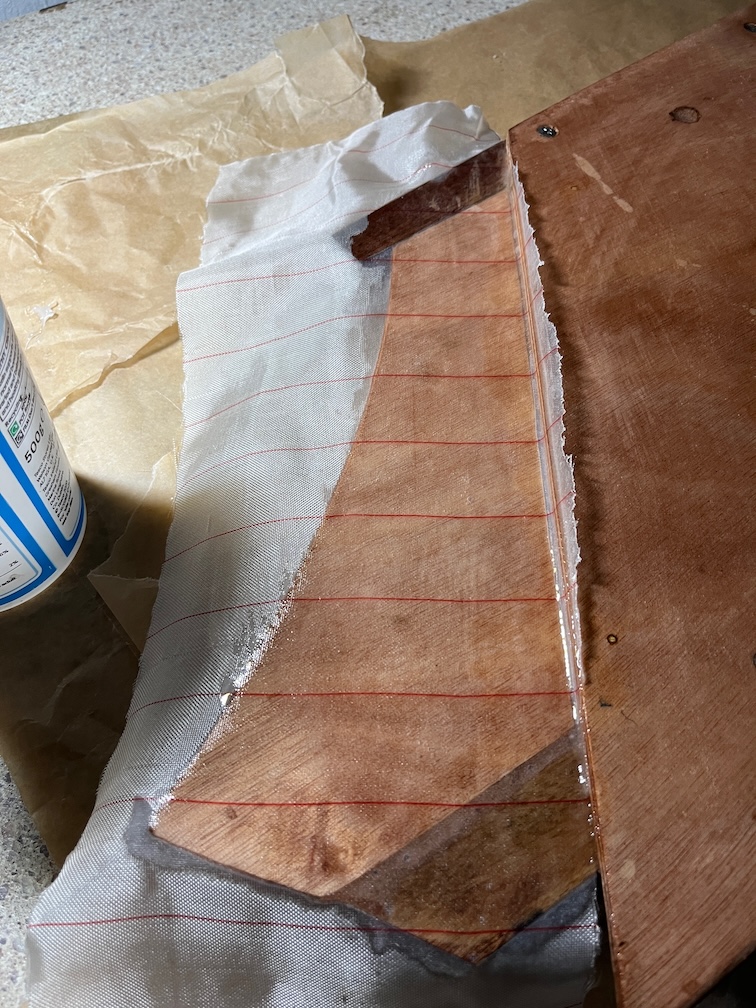
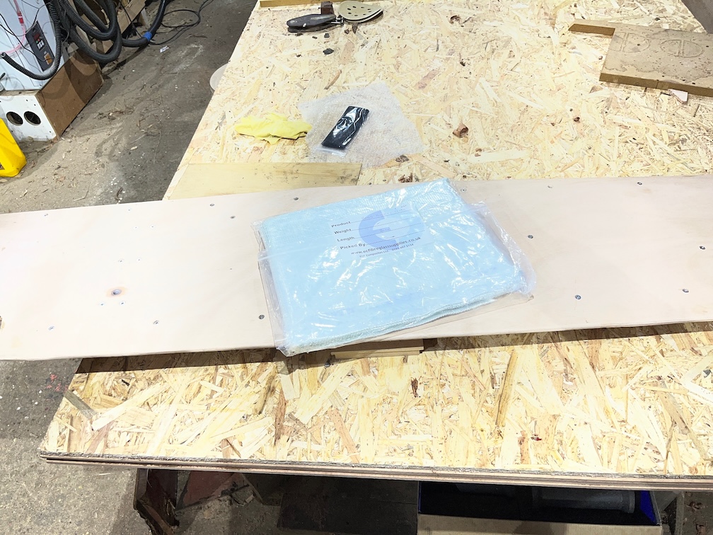
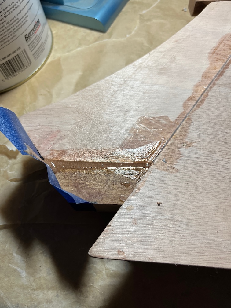
The paper template was cut out and I used it to see if I had any pieces of Sapele that would be big enough. Sadly not and two pieces were cut out and glued together.

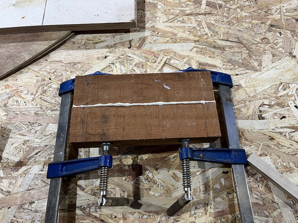
The thickness of the Sapele is 44 mm (ish) and the aft block is 37.7 mm, probably 1 1/2″ that has been sanded down. I will run this block through the planer once the glue has dried to get it to 38 mm and smooth on both sides instead of the rough sawn finish that you can see here.

It is quite useful to note that three of the sides of the offcut are straight lines and only the aft edge is curved. This is going to make cutting the new piece out fairly straightforward, at least I hope it will.

But that’s a task for tomorrow.

Time for a cup of tea.

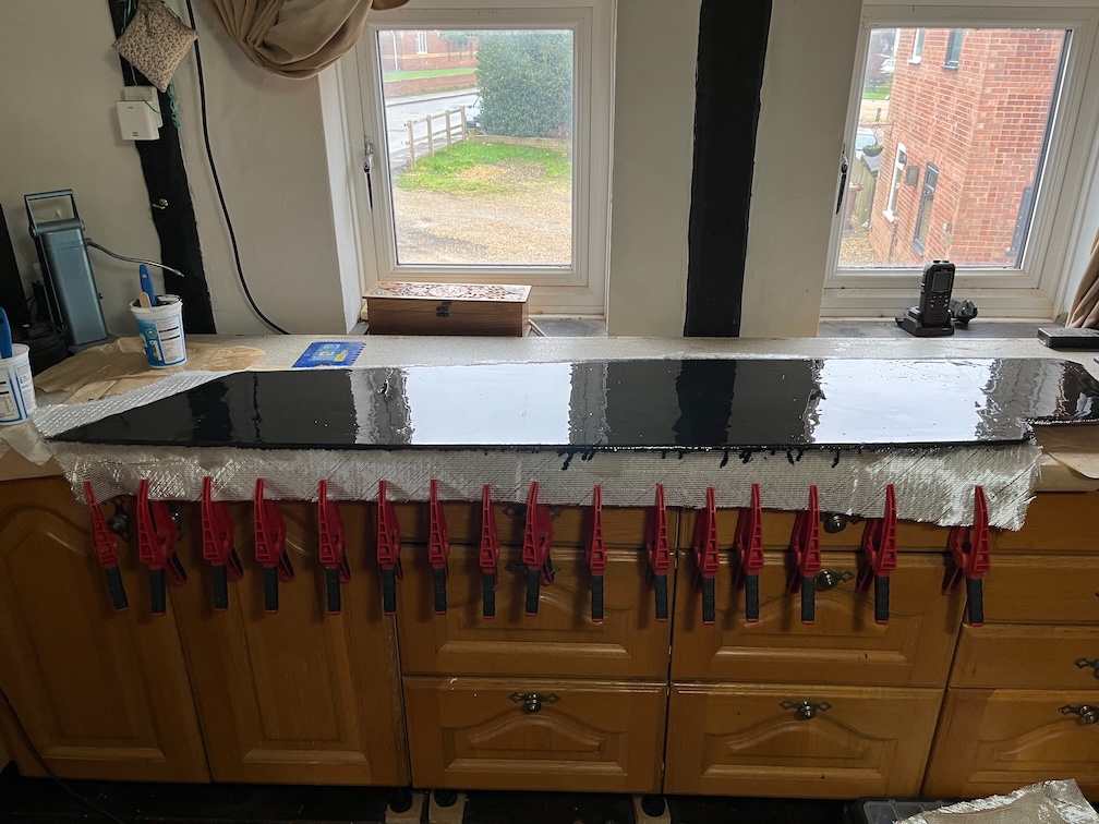
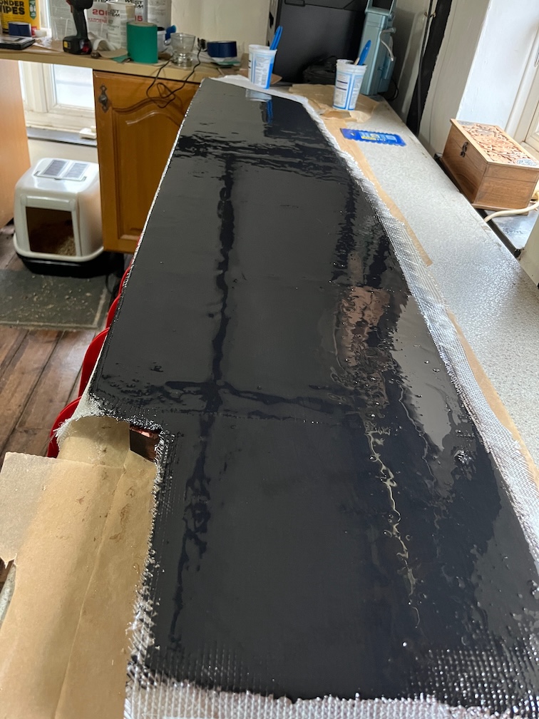
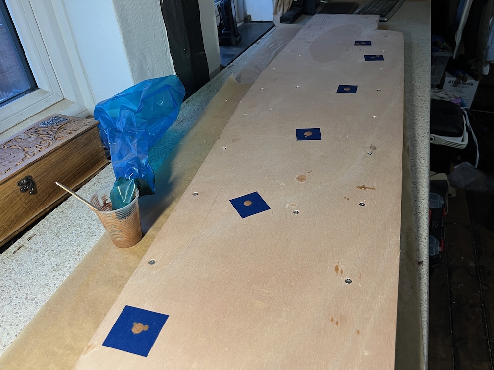
Finally for today, the two galley stove boards received their first coat of varnish.

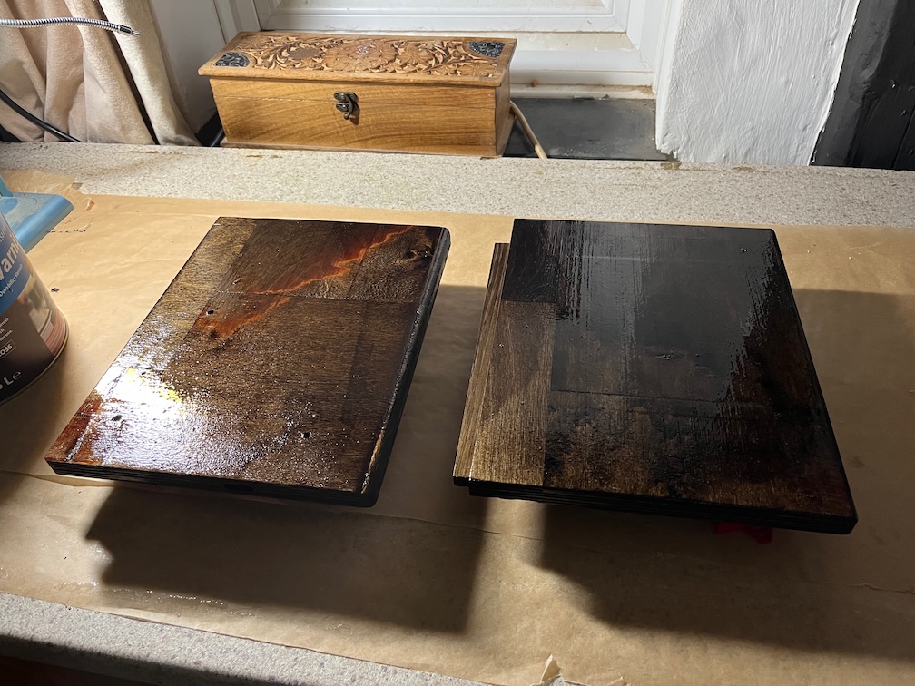
The tops of the boards will receive four coat with the undersides getting two, possibly only one.

That’s the lot for the day.

Time for a cup of tea.

2026-02-08 – Galley Stove II

I put the diesel heater on when I went out to feed the outdoor cat this morning, meaning to give it half an hour and then to turn it off. Well, I forgot and it was nearly two hours. Still the inside of the cabin was very warm and toasty.

The next part of the galley stove task is to see if the laminates worked and then to make a cardboard template followed by a gash plywood template followed by the real thing.

All the cramps were loose, one had even fallen off, I presume due to them expanding in the warmth. Still, the laminates were still in position.

There is a pretty even gap under the curve but that is acceptable since there is a step at the inboard end that you can see in the top left of the above photo. It seems that the curve worked.

The glue up for the board and lid also worked, or so it seems.

Firstly the cardboard template. The procedure is cut to the curve then cut the inboard upright to fit and then hot glue pieces to the template to make it fit elsewhere.

This is the real thing. I’ve not extended it all the way up to the outboard edge of the cup shelf, that is unnecessary.

I used cedar battens to hold the piece in place screwed but not glued so that I can remove it if required in the future.

A short length of cedar was used to secure the piece to the underside of the cup shelf. Screwed into the shelf and glued and screwed on to the work piece.

This is the “inside” face of the workpiece. Not a perfect fit, but it does not need to be. Where there is a gap under the side will be the part where the stove is stowed. Outboard of this, where there will be a small storage area, there the side is a tight fit. So, good enough.

Time for a cup of tea (and lunch).

Having done one side it is time to do the other.

I clamped two battens to the front and back of the locker so that the new side is exactly parallel to the first.

I used the gash plywood template to see how different it is going to be and as you can see, that’s not a lot of difference between the two.

I cut the bottom of the cardboard template off and hot glued that to the plywood template in the correct place.

A near perfect fit and this is the real side.

As with the first side, cedar battens were used to fix the side to the inside of the locker.

After much measuring, cutting toing and froing the galley stove has somewhere to be stowed.

There are two vertical channels currently super-glued to the sides.

I’ll screw these in as well now that the fit has been sorted out.

At the back a lip under the galley stove goes under that back piece.

Like so and this prevents the back of the stove from lifting up should there be a sudden jerk from outside such as a passing fishing vessel.

The front of the stove is far enough out such that the heat from the flame will not be near anything it shouldn’t be !

And under the front I have put in a spring latch which prevents the front from lifting up accidentally.

With the gas cylinder installed and the stove in place you can see that there is a small amount of space outboard of the cylinder. If there is ever a problem with the cylinder working loose under way that I’ll put some foam on the cup holder that will press against the cylinder, hopefully preventing it from working loose again. Not needed now and hopefully never.

So, everything works and all that is left to do for this task from a construction perspective is to make a lid to cover the stowed stove.

But not today, that’s enough.

Time for a cup of tea.

2026-02-07 – Galley Stove I

Despite the air temperature being 9º C this morning, when I went out to the workshop my fingers were too cold to work within 15 minutes. The wind is bitter, it is raining and it is pretty miserable.

So I went back inside and had a cup of tea whilst I decided what I could do today that did not require the accurate use of sharp tools and which would allow blood to stay on the inside and not leak out.

Having warmed up I went out again and put the hatch on and screwed in the retaining screws. Task No.1 completed.

The work on the compass cable went so well yesterday with the centerplate case out of the way that I looked around for anything else that would benefit from being done before the case is reassembled. There is only one thing on my list and that it the galley stove. While this might not be considered by some to be essential sailing equipment, I’m a mug of tea sailor in that it my mug of tea gets spilt, I have too much sail up or it is too windy. Can’t do that without tea and can’t do tea without a stove.

Ergo, essential sailing equipment !

Besides, it has to be done at some point.

In the stowed position the stove will be like the above in the locker where the old stove used to be.

The board upon which it rests will slide into channels in the locker and for this reason the board is wider than the stove by about 15 mm either side. This board is gash plywood and I’m using it to get the sizes and holes positioned correctly.

The stove is bolted to the board with three bolts. Two through the existing feet and one extra to hold it steady.

The normally removable pot stand is also bolted down but this time just to the stove.

The long bolts will hold it in position so that it doesn’t fall out when the stove is in the stowed position and will not be very tight.

I had to stop at this point as I don’t have plywood that is thick enough and good enough quality of the right size to make the real board and the locker lid, so I glued some smaller pieces together and I’ll cut the board and lid from the resulting single piece. This plywood is Baltic Birch and too thick, so I’ll plane it down and varnish the lid once it is all done.

I didn’t think about the size of the glue up before clamping it, but it just fits over the Rayburn.

I’m a little doubtful about this glue up. The squares were glued and clamped in a length of five and a half squares using domino tenons to locate and strengthen the joints a bit. This glue up is two of those short boards joined length ways but I forgot that I had a domino jointer (it is a recent acquisition) and just glued them together, so this might fail. We shall see. If the joint does not hold then I’ll just cut off the glued edges by about 2 mm and then glue it back together again but this time using the tenons.

I decided that I would also check that the compass wiring works and put the compass into position in the cockpit.

The lighting wires were connected to the power cable and for now, that is it since it is quite light and I’ll need to try this out when dusk falls. You can also see the problem with the connector. If I leave it like this it is going to get hooked on something and ripped out. Once the compass is bolted in place, I’ll try sticking it to the underside of the bridge deck with some butyl tape. That stuff is very sticky and might to the job,

Time for a cup of tea.

Even with the centerplate case removed, making a template for the curve of the hull inside the lockers would be a trial, so I decided to try an alternative method. I took one of the thin strips of wood that I’ve had in the workshop rafters for the last seven years or so, left over from the Naiad rebuild and too good to throw away but never needed before, and cut it into lengths that will fit around the curve.

I applied glue to one side of the strips and put them into place, pressing them down with battens. The idea is that once the glue is dry I will have a short laminated piece of wood that has the same shape as the inside of the hull. We will see, because there may be some spring-back. Even so, it should be close enough to get the first template cut and I can use the belt sander to whittle away any sections that need adjustment.

The batten arrangement is a bit haphazard, but it works. To improve the glue setting time I put the diesel heater warm air hose into the cabin and into the locker and turned it on at its lowest setting. An hour or two should have warmed the locker space and the laminates up somewhat.

Again, we shall see.

Time for a cup of coffee (fooled you!).

I let the heater run for thirty minutes and then checked it.

It seemed to be working well, so I left it running.

I also checked the compass light which,as you can see, is also working.

It’s been a good day, despite the initial cold, but I think it is time to call an end to the Shoal Waters tasks until tomorrow.

Time for a cup of tea.

2026-02-06 – More of the Same

Not surprisingly, the tasks for today were pretty much the same as yesterday. An early start to get the first layer of epoxy on the second case side and so on and so forth. Didn’t bother with photos for the second side, it’s all the same as the first.

The new ship’s battery arrived this morning, which was a bit of a surprise since it was due to arrive next Tuesday, not that this is a problem, just that I wasn’t expecting it today.

Here is the new battery on the bridge deck instead of the old one. I can tell that it makes a difference since when you turn on the cabin light, the battery voltage does not change whereas with the old battery, the voltage would drop by half a volt or so. The cabin light is a 5W bulb meaning that the bulb draws around 416 mA from a 12V supply and a battery in good condition should not show an appreciable voltage drop.

However, I might have made a slight mistake with the measurements.

I measured the gap as 320 mm as you can see here, although looking at the photo now, the real gap will be 340 mm since the inboard end of the battery will be sitting on the lower runner so that it is level (ish).

But, and this is a big but, I forgot that there will be a centerplate case support here that will reduce the width.

Holding the support in place I can see that I just have 310 mm, which is the width of the battery, so the battery will go through the gap…

…but only is I take the door off !

So, a mistake, yes, but not a bad one. I mean, how often will I be taking the battery in and out? Maybe twice a season, once at either end, but probably not even that.

The door had to come off

“All right,” said Fred, “Have to take the door off
Need more space to shift the so-and-so.”
Had bad twinges taking off the hinges
And it got us nowhere
And so, we had a cuppa tea

The door came off without too much bother, only one screw caused a problem as it sheared off in the jamb. Annoying since this means that I will need to move the hinge so that the new screw doesn’t try to screw down through the old one.

Door with all the fittings removed.

The fittings and fixings. All brass except two stainless screws. All the fixings bar the stainless ones went in the bin and I’ll replace them with A2 stainless. I did think of replacing the hinges and latch with stainless equivalents, but they are still good enough or will be after a bit of cleaning.

I’ll not replace the eye straps as these were for the bungee that restrained the Camping Gaz bottle when using the radiant heater and we don’t have that anymore, so the eye straps are redundant.

Anther small task was to run the power cable for the compass light. This would have been a total pain were it not for the fact that the centerplate case has been removed allowing me to lie on my back with my head under the bridge deck from whence I could hammer in the small cable clips to hold the cable.

As before, I used small bronze panel pins instead of the steel nails that come with the clips.

And this is the result. The round cable is the power cable to the starboard navigation light and the black and red cable is the one for the compass light. There are a lot of other unused clips in there. There are two possibilities. The first is that there used to be another cable possibly for a quarter berth light and the second is that the cable was put up by feel from the cabin and these are the clips that failed that exercise.

I put a lever connector on the end but left it dangling. This will be connected to the cable from the compass and I’ll have to find a way to stick it to the underside of the bridge deck but still accessible so that the compass may be removed from time to time. Not sure how to do that yet.

I used a carpet offcut over the keel to make things a little more comfortable.

Talking of the compass, I was not happy with the way in which the LED wires were dangling out of the bottom of the housing, they are thin and not strong, so I took the compass apart and extended the wires using two lever clips. The connector and the wires were held down with hot glue.

The new wires still hang out of the bottom of the housing, but they are longer and more robust.

Well, I think that is a good place to stop for the evening.

Time for a cup of tea.

2026-02-05 – Adding the Glass Mat

The final stage of the case sides before fitting is to sheathe the inside of the case. Since there are going to be three epoxy applications per side and the second and third layers need to be applied whilst the prior layer is still chemically active, this is going to be an all day event, sort of. It will be apply the next layer and wait. Repeat three times.

I set everything up yesterday evening and first thing this morning I started.

The first layer is unthickened epoxy spread onto the inner side. This is allowed to soak into the wood for a while before the next layer is applied.

There is a slight wrinkle to this layer in that the aft end has a part that is not inside the case but goes alongside the aft block. This part has only one coat of epoxy and needs peel ply added to remove the amine blush once the epoxy has cured.

Now we wait for this layer to start curing. The stage we are looking for is when the epoxy gets to be about as tacky as Sellotape.

Time for a cup of tea.

Three hours latere the next stage is done.

The cramps hanging down over the edge of the case side are there to ensure that the glass mat drapes over the curved edge of the plywood without any lifting. I have done this to ensure that the edge of the glass mat will be under the bottom edge of the side when installed. This means that when the centerplate is lifted up, there will be no edge of glass mat to catch on the plate and eventually tear off. This way there is just a smooth curve and no edge.

I hope.

Time for a cup of tea.

Finally, for the coating of this side at least, the third layer.

This layer has graphite added to the epoxy, 10% by weight, to form a more lubricating surface. The result is a black epoxy layer which looks really nice to my eyes. Shame it is on the inside and will not be seen when the case is assembled.

I will give it a few moments to level out and then I will wave a hot air gun over the surface to pop any bubbles that remain after the mixing.

This has to be left for 24 hours or so to achieve full strength and then I will take it down to the workshop and trim the edges of the glass mat. After that it will be the turn of the other side.

Time for a cup of tea.

2026-02-04 – Compass Continued

The brass machine screws arrived this afternoon so once work was done I went down to the workshop to fit them. Although the required length is just 12mm I bought ones that were 20mm in length and cut them down to fit. The reason being that I’m more likely to use 20mm lengths and they come in packs of 20.

It didn’t take long to cut the machine screws to length, grind the ends so that a nut fits and then to fit them to the outer housing.

I still do not have a simple way to mount the LED in the bottom of the outer housing, so I just made up something that will do for now and if it proves to be deficient in any way then I can find a better way then.

I did take the time while the light was still in the sky to sand and put the fourth, and last, coat of varnish on the hatch runners. Once this is hard I shall put the hatch on, probably in a week or so since the temperature is still in the single digits and will be for at least the next week according to the forecast.

The mounting of the LED is not that difficult, it is the wires that are the problem.

So this is the way I’m going right now. This is the underside of the LED mount with the LED and the wires held to the wood with hot glue.

I have reassembled the compass, now to try out the lighting.

I have a variable power supply in my office which I set to 12V and connected the LED. This is the result with the office light on.

And with the office light off. Not at all bad.

Except that the inner housing has been put in backwards and the lubber line, which should at the front of the compass is at the back. So I will have to change that.

While I had the compass open again I took a photo of the LED mount. As you can see, it is very simple. Hopefully the huge blob of glue I put on the wires and wood will hold and stop them from being torn off.

Here is the compass the correct was around. You can see the word AFT on the outer ring at the bottom and the lubber line now opposite, where it should be.

So, the compass is done and now needs to be installed into the cockpit. But, since I get into and out of the boat on the starboard side, putting the compass in now would be right in the way, so I’ll put it aside somewhere safe and install it closer to the launch day.

Time for a cup of tea.

2026-02-03 – Compass Refurbishment

Shoal Waters was fitted with a ‘ fine brass binnacle compass’ (Sailing Just for Fun p113) and whilst it originally had a detachable domed top, complete with viewing window and side illumination, this has gone missing somewhere back in the mists of time. Still the compass survives but needs a little work.

Here is the compass disassembled. Originally, before being installed in Shoal Waters the compass gimballed in all axes, but Charles removed the fore and aft gimbal so that it just gimbals side to side.

I drilled out the 1/4″ holes in which the lugs of the compass inner housing located and press for four roller bearings, two in each side.

The lugs are quite sturdy and fit securely into the bearings.

The Bakelite bearing supports rest on two flat Bakelite pieces screwed to the outer housing and held in place by screws from the outside. These, being brass, had started to soften so I’ve ordered some more, but M5 bolts this time.

The holes in the Bakelite bearing supports were drilled out to 4.2mm and them tapped with a 5mm tap.

The bolts secure the supports inside the outer housing.

I used the M5 stainless bolts that I had available but these will be replaced with brass once they arrive.

The next task is to mount the red LED inside the housing which is not as easy as it sounds since the LED must not be too high or it will foul the inner housing as it gimbals.

This is where the compass is mount in the cockpit and you can see the small hole for the LED as it was originally mounted in the bridge deck rather than in the compass. I aim to change that and just have the wires go through the hole, probably through some sort of grommet that will also serve to stop water from going down the hole.

So. it is time to put the thinking cap on and devise a way to mount the LED.

Time for a cup of tea.

2026-02-02 – More Small Tasks

Just a few small tasks today, starting with applying the third coat of varnish to the hatch runners on Shoal Waters.

It is also time to apply some slippery gunk to the hatch itself. I made a jar of furniture wax a decade and a half ago consisting of beeswax, linseed oil and White Spirit for several projects I had back then. I made a lot more than I needed, but it has proved useful during the intervening years. I recently used it on two rope winding heads, on the teeth of the wooden gears.

Today I’ll use it on the htach.

This is the before photo, you can see that the wood is mostly untreated. It might have been treated with something originally, but years of sliding back and forth on the runners would have worn it off.

This is the after photo. I’ve applied two coats of the mixture. The white spirit acts like a solvent for the linseed oil and beeswax and penetrates the wood. The the spirit evaporates quite quickly and after that the oil slowly polymerises. The effect is to carry some of the beeswax into the wood leaving some on top of the wood.

The nice thing about this mix is that after a few days the surface of the wood is just covered with a thin layer of wax. If you get it on your hands or clothes, it is easily washed off.

The last task for today, I’m having a ‘rest’ day and not doing that much, is to cut the glass mat. I bought 2m of 1.27m wide 300g biaxial glass cloth and it needs to be cut in half.

Half of the mat covers the case side with plenty to spare, although I’ll probably need to cut it down to size a little more once it has been placed onto the pre-epoxied wood but before it is wetted out.

After this I folded both pieces up, put them into the bag it came in originally and took both the glass mat and the case side back into the workroom for the next stage.

Which will not be today !

Time for a cup of tea.

2026-02-01 – Port Centerplate Case Side, Again

It is February already and I need to get a move on. Still lots to do and time is starting to run out. The task for this wet and dreary day is to complete the construction of the port case side.

Unfortunately, the runner sprung slightly when I removed the cramps and I’ll have to do two things to rectify this. Firstly this gap needs to be cleaned out and filled and secondly, the runner will need to be trimmed on the bottom to compensate.

The first part is easy, a sharp chisel and some sandpaper and he job is done. The second part can wait until later when the pivot bolt hole is filled with epoxy.

Next task is to drill out the pivot bolt hole and to do this both case sides are clamped together and a 10mm drill drilled down through the completed starboard side drilling out the epoxy filled hole on the port side.

The next task is to make and fit the vertical support. Here I have already fitted the metal plate and marked the places where the screws will be put in from the inside.

The support was located using a 10mm drill bit through the support and the case side and then clamped in position so that the holes could be drilled through from the other side.

This is the inside and you can just see the tip of the 10mm drill bit in the pivot bolt hole.

Two of the holes were drilled and countersunk, then screws put in place to hold the support whilst the remaining four holes were drilled, countersunk and screws fitted. I use a vertical drill guide to make sure that the holes are drilled, well, vertically to the workpiece. I also drilled out the bolt hole to 13mm as was done before for the starboard side back on 1st January.

Once this was done, the mating sides of the support and case were lightly sanded, glue applied and the support screwed in place. The glue squeeze out was removed to reduce the work needed to clean up later.

Time for a cup of tea.

Having fixed the support in place it was time to move on to the diagonal brace.

I made a paper template from the first side and used that on the small angle jig.

Like this. This it was just a case of cut the end of the brace, make a template for the other end and then cut that to give me the brace with tapered ends.

Mark the position of the brace, drill holes through the side, clamp the brace in place and drill into the brace from the other side and chamfer the holes. Then glue it all together. Then I started shaping the ends to meet the runners and realised that I had made a critical error. The brace was the wrong way round !!

Fortunately, the glue had not started to set, so I hastily removed the screws, cleaned the clue (water soluble whilst still liquid) and put it on the other way around.

Here is the result and you can see where the brace was before. I’ll have to put epoxy in the screw holes to fill them up but I have to do that for the pivot bolt hole and the sprung section I referred to earlier. Once the side is installed into the boat and painted you probably will not notice the error. At least I hope so.

Now I definitely need a break.

Time for a cup of tea.

Before I took a break I brought both case sides up into the house to be in the warm since the next major task will be the epoxy, glass and graphite layers on the inside faces and the wood should be warm for that. Well, warmer than outside.

Then I took my tea break.

One I had consumed the tea I took the port side into the workroom, drilled out the errant screw holes to 12 mm, put squares of blue painter’s tape on both sides of each hole, making sure that the tape was pressed down firmly, then cut the tape on the top side to reveal the holes. The sprung section had tape put on the underside. Into these holes I put epoxy thickened with low density filler mixed to the consistency of double cream. I want it to flow into all the holes and fill them up without me having to press the epoxy in with a putty knife.

This is the sprung section.

And these are the screw holes. The blue bag you can see in the photo is a piping bag that I bought when I rebuilt Naiad. Well, I bought a roll of 100 catering piping bags and they are great for this sort of work and for putting down epoxy fillets with a stiffer epoxy mix. I used the slow hardener for this job so that the epoxy has time to seep into the wood fibers before curing to make sure that the hole is made completely watertight. A bit of an overkill, really, since this is the side that is going to be glassed but doing this gets to be a bit of a habit once you have done it a dozen times or more. Any hole that I make in a wooden hull, for example, is drilled out over size, filled with thickened epoxy and the correct sized hole drilled into the epoxy.

Before calling it a day I sanded the hatch runners on Shoal Waters and applied a second coat of varnish. It is currently 8º C and is forecast to be 6º to 7º between now and this time tomorrow, so the varnish should dry well in that time. Wednesday and Thursday are forecast to be a similar temperature, so I should be able to get another two coats on to complete that task. Then I’ll have to wait a few days for the varnish to harden completely before putting the hatch on.

The hatch is by the Rayburn until it is needed having had four coats of varnish all round. The day before I put it back on to the boat I need to grease the parts of the hatch that touch the runners so that it slides easily.

As I went out to the boat to apply the varnish, I noticed that I had left the cabin light on from this time last night. That means it has been on for 24 hours. The battery is an old one and doesn’t hold charge well any more, but the light was still on. Mind you, during the day I expect that the majority of the charge to the light came from the solar panels.

That, I think is it for the day.

Time for a cup of tea.