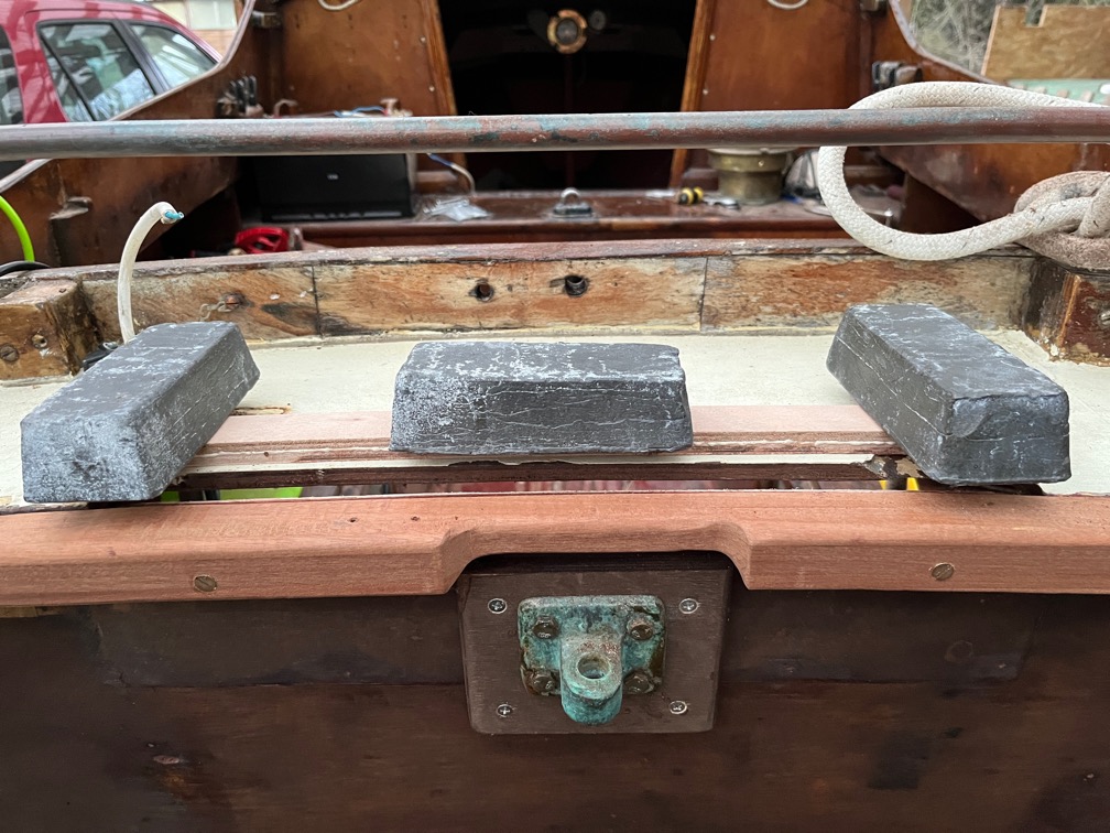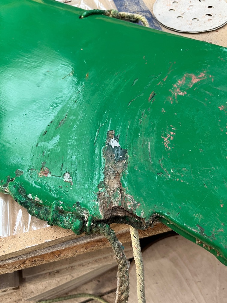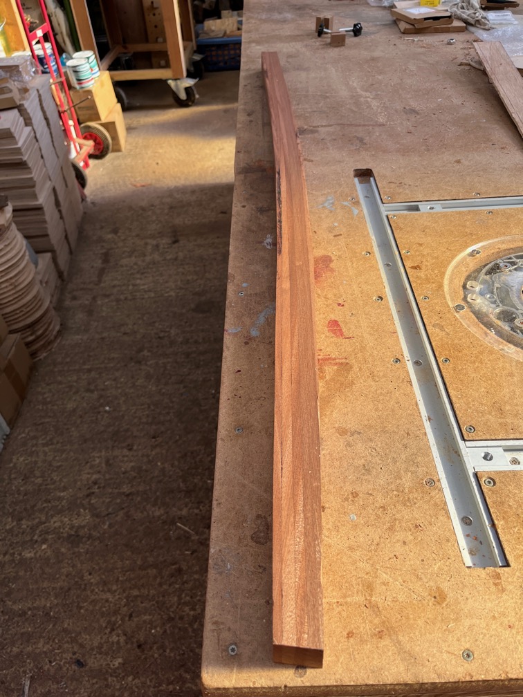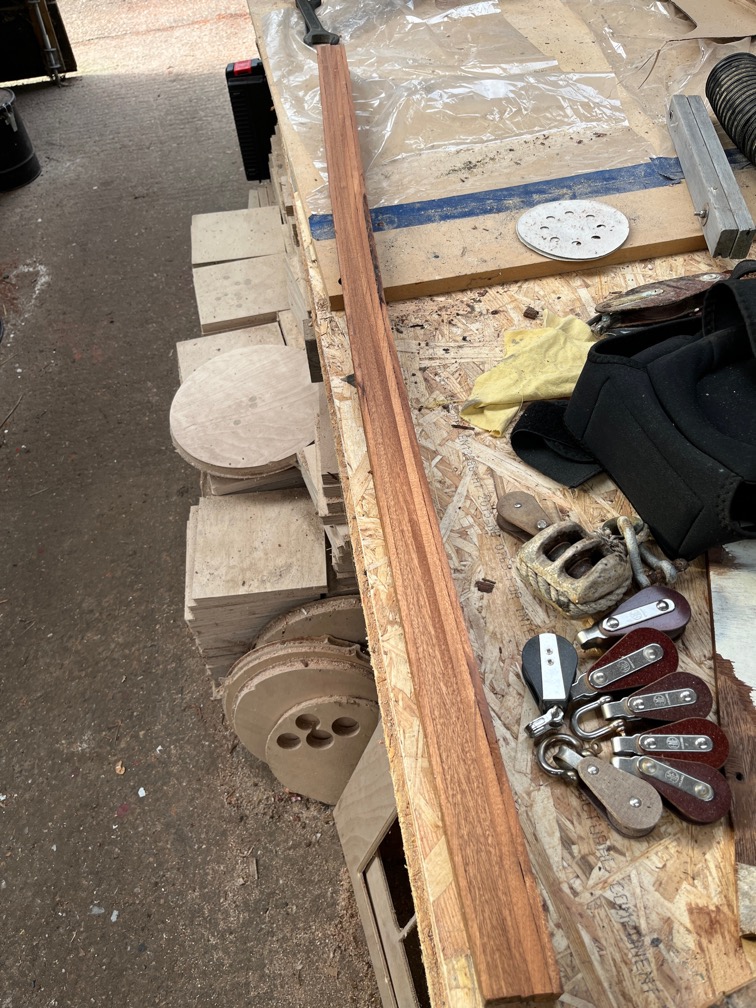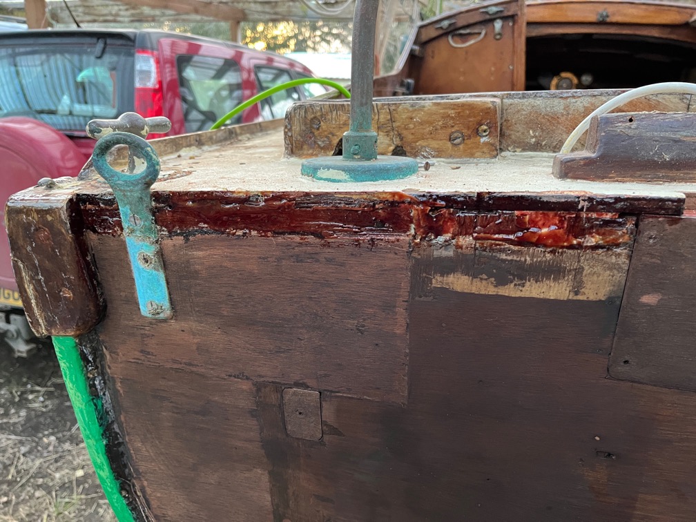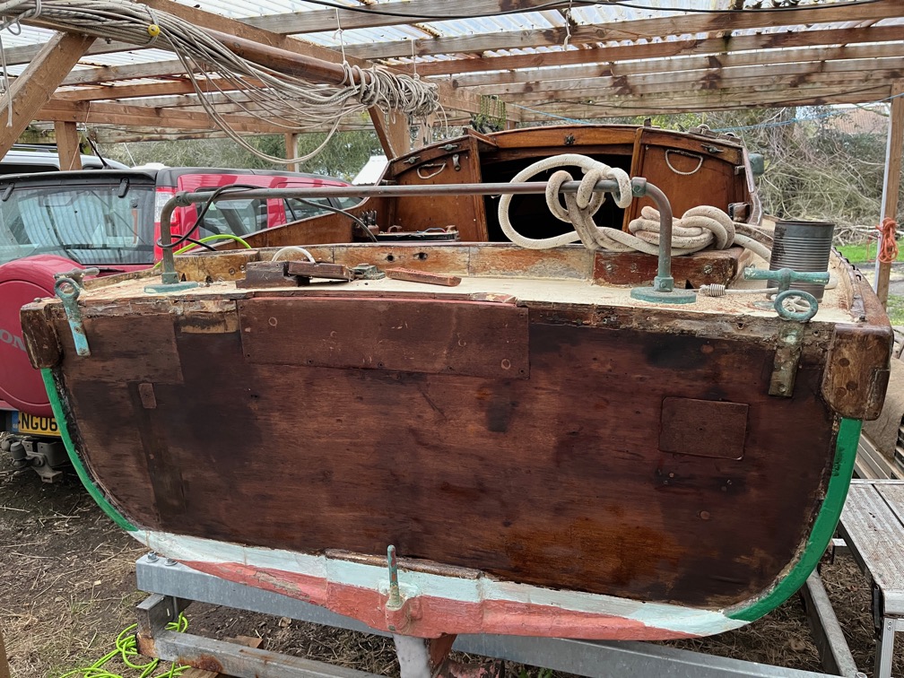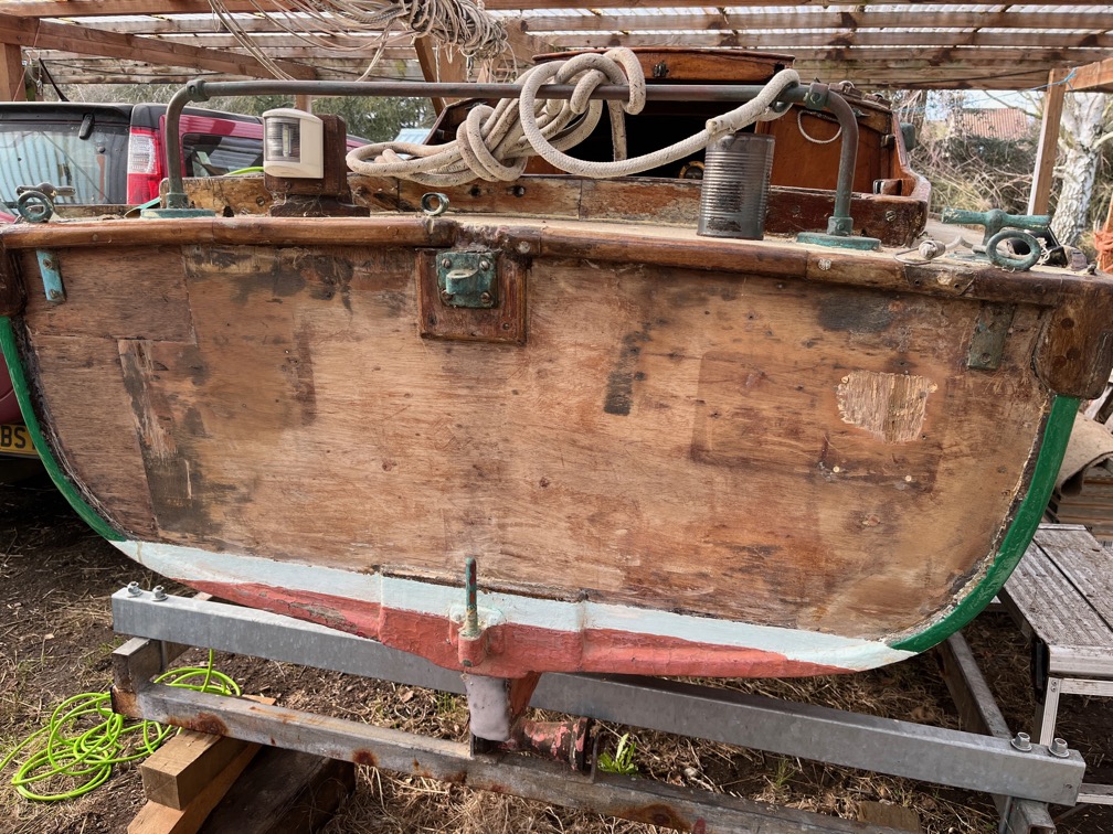
The first task was to get the graving piece for the aft deck sorted out.
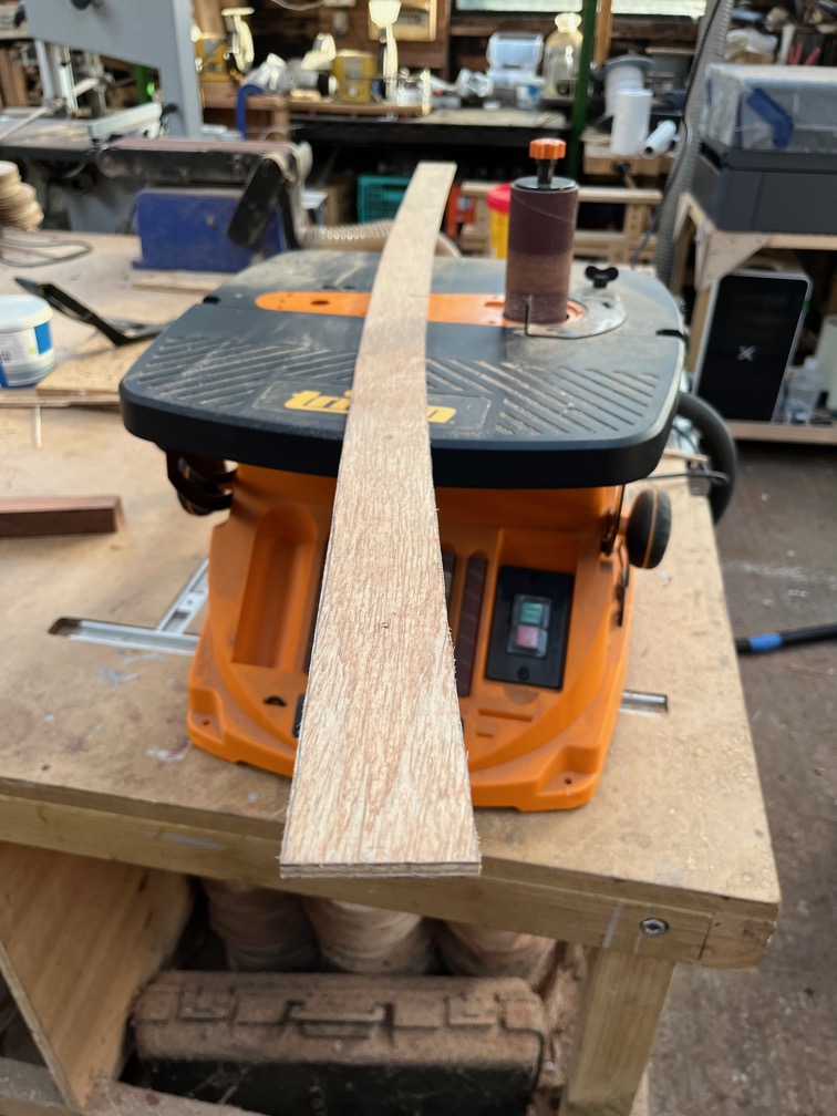
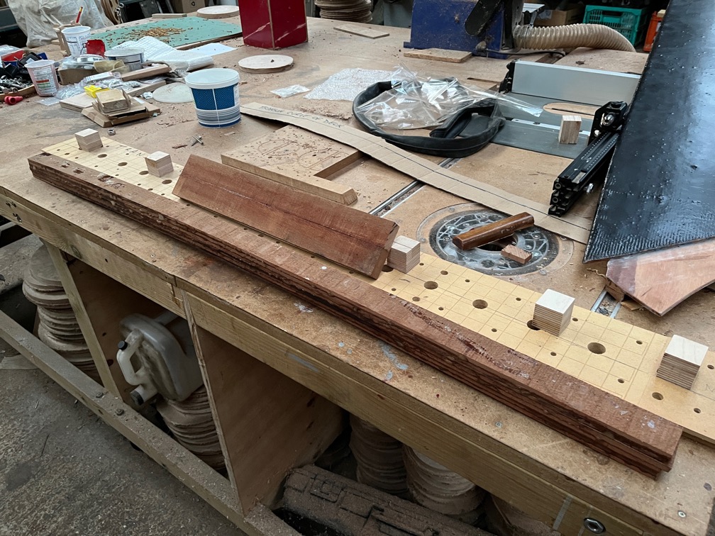
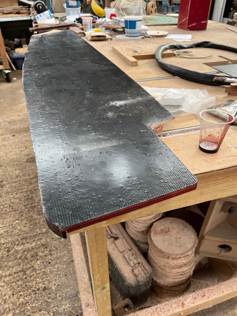
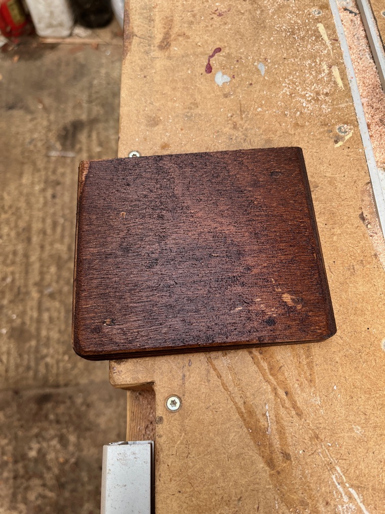
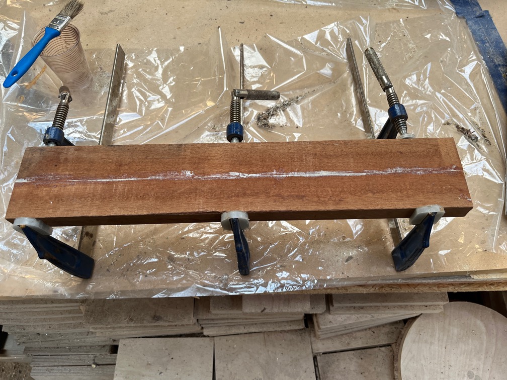
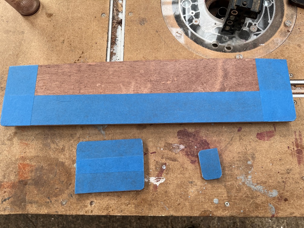
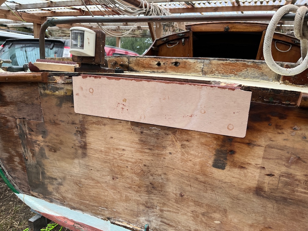
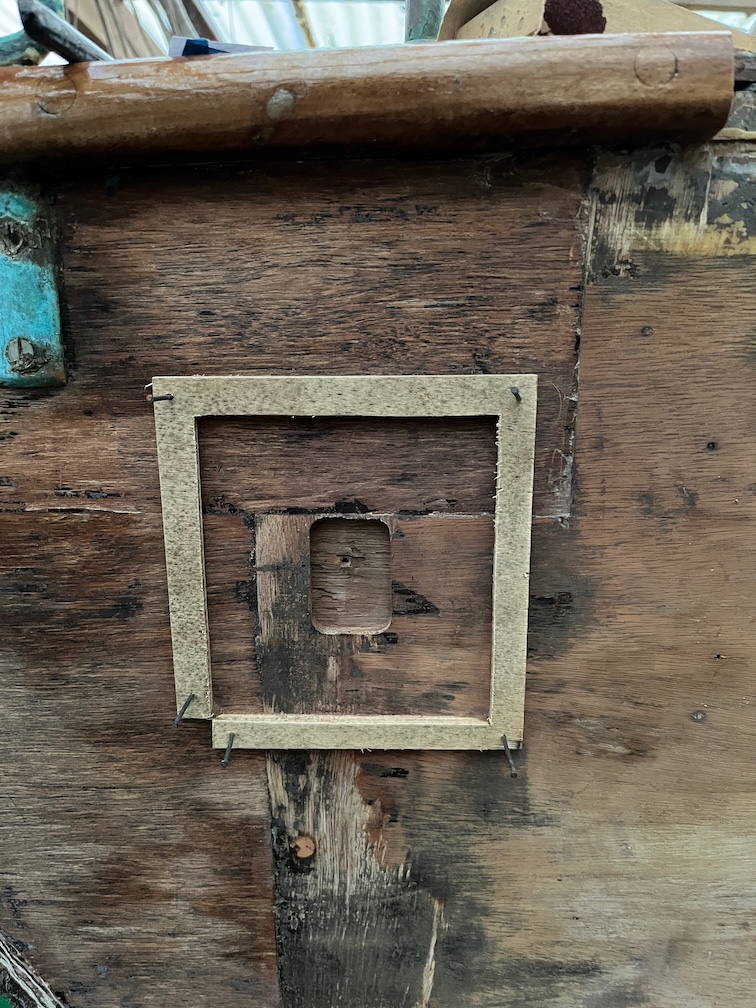
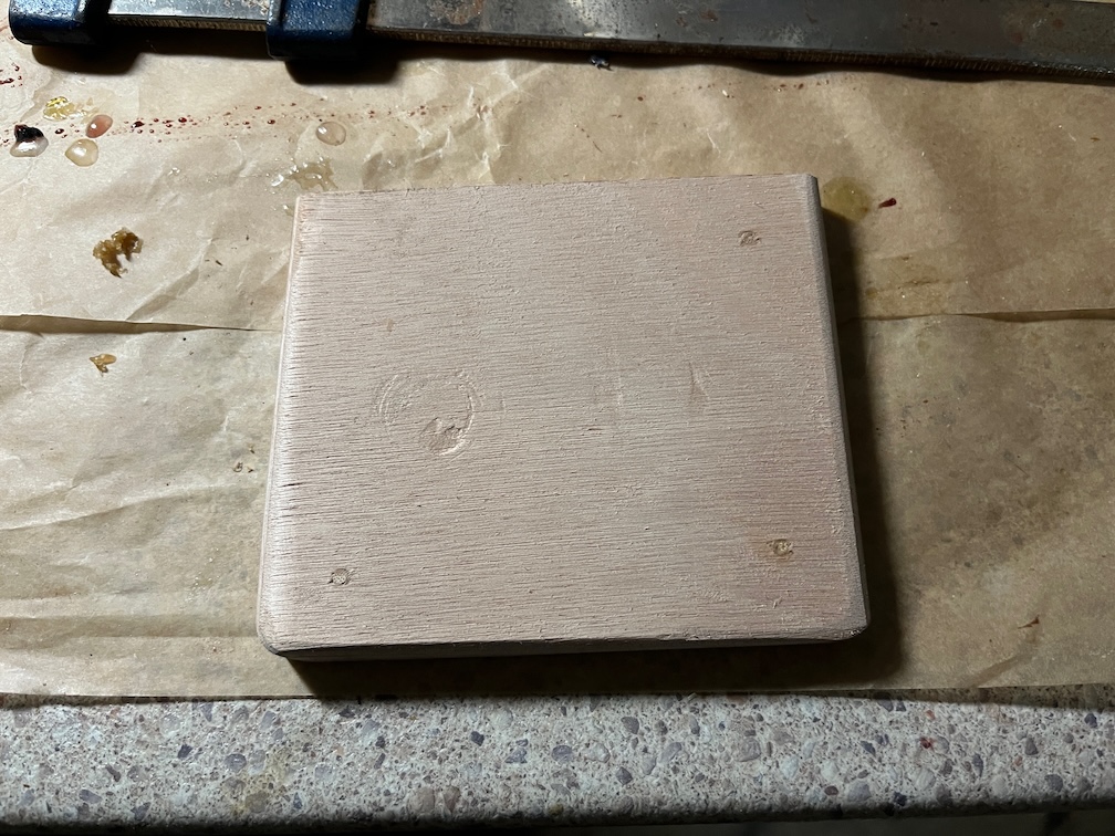
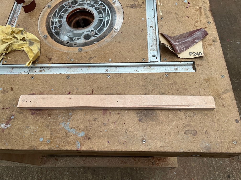
This is the graving piece with the weights remove and it is a pretty good match for the top of the deck. That does mean that it will be a little out when put in place, which is lower down, but not by much (I hope).
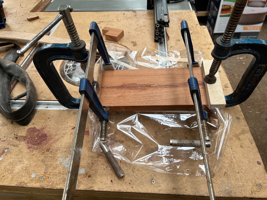
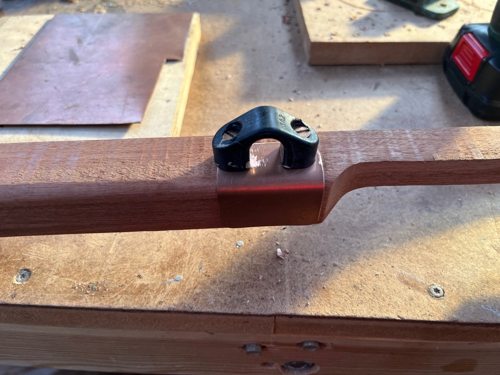
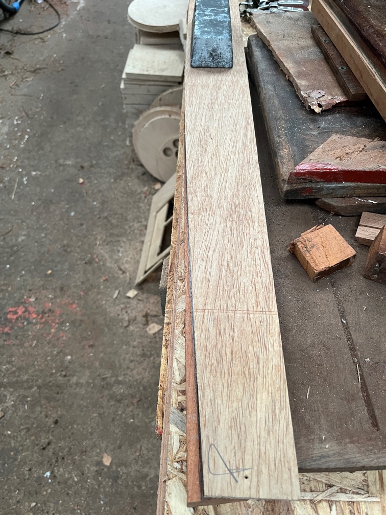
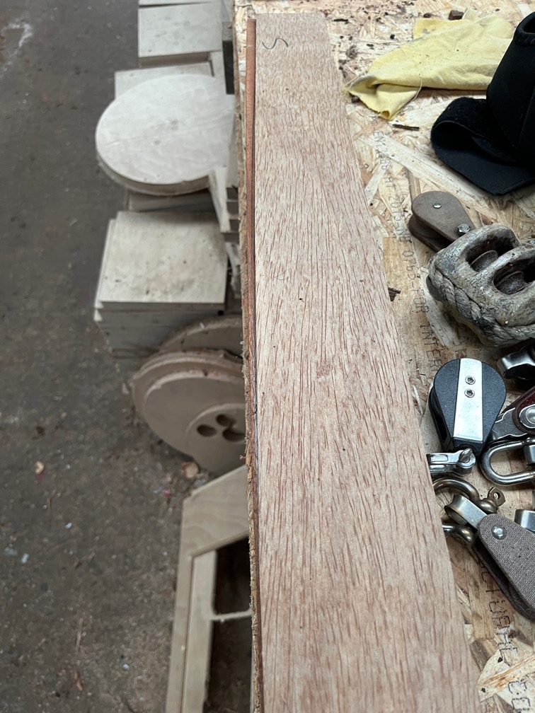
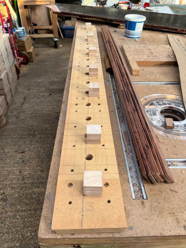
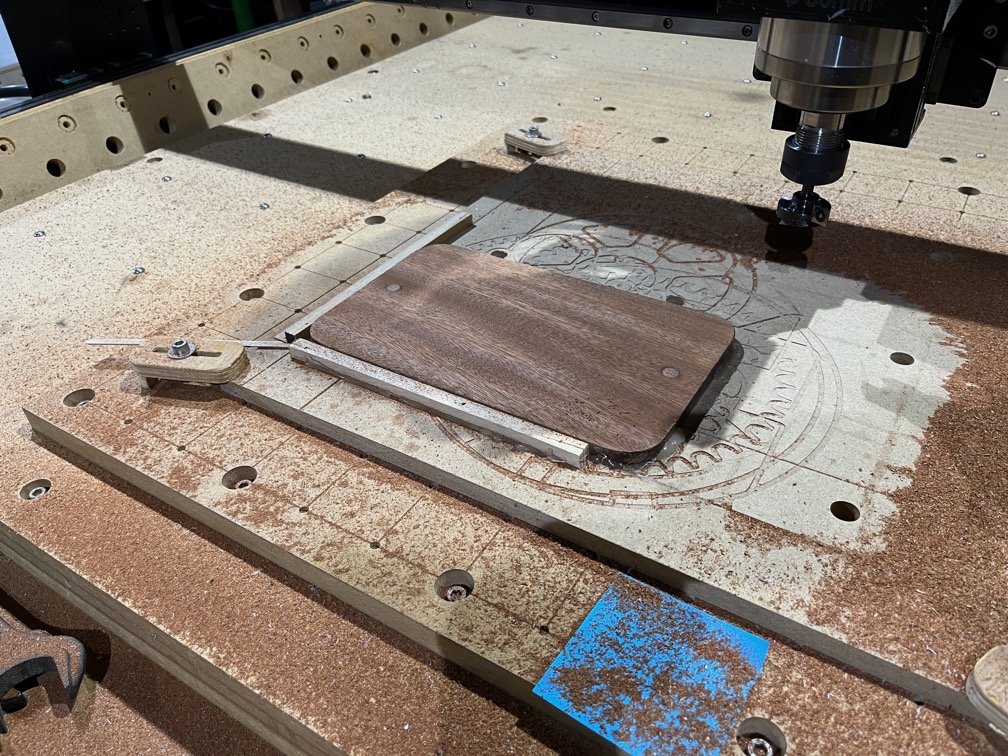
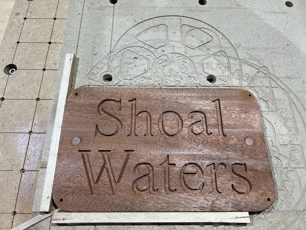
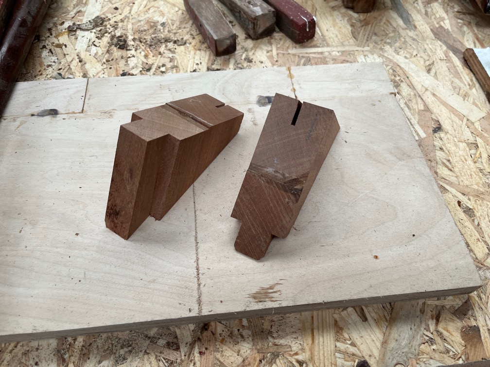
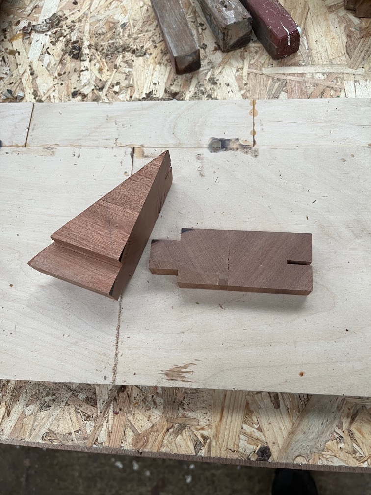
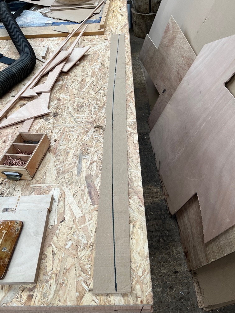
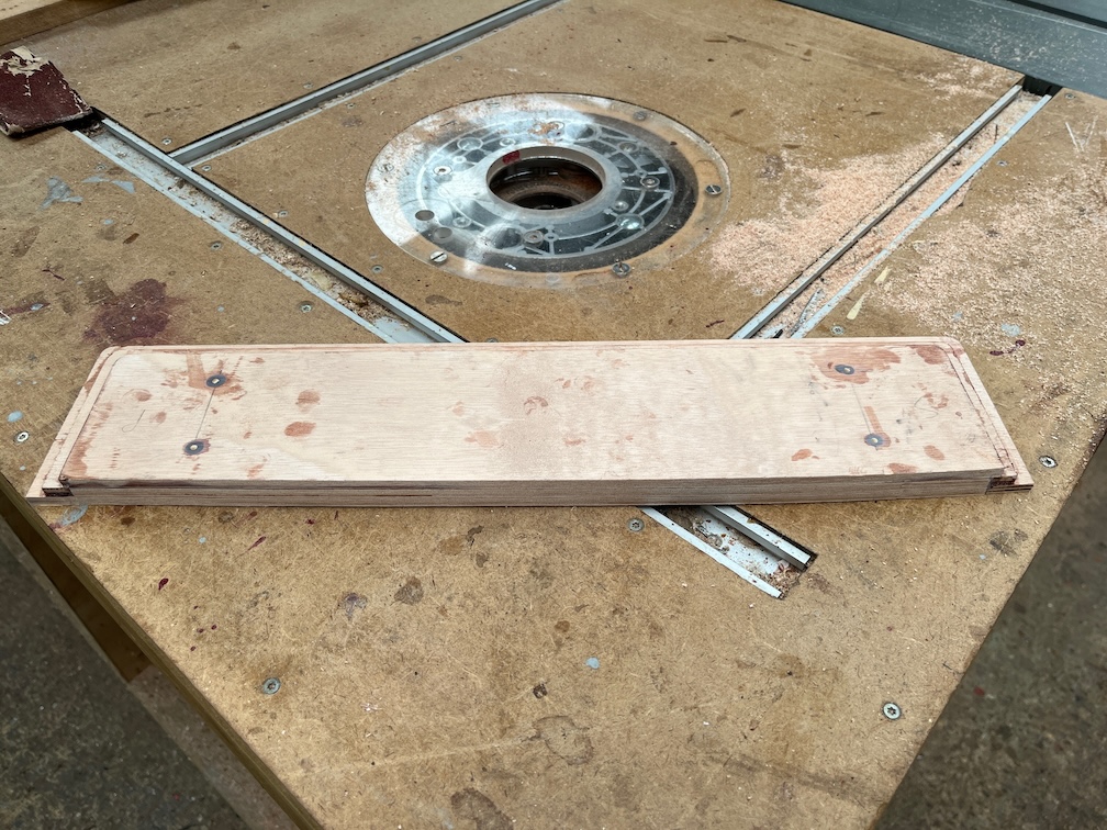
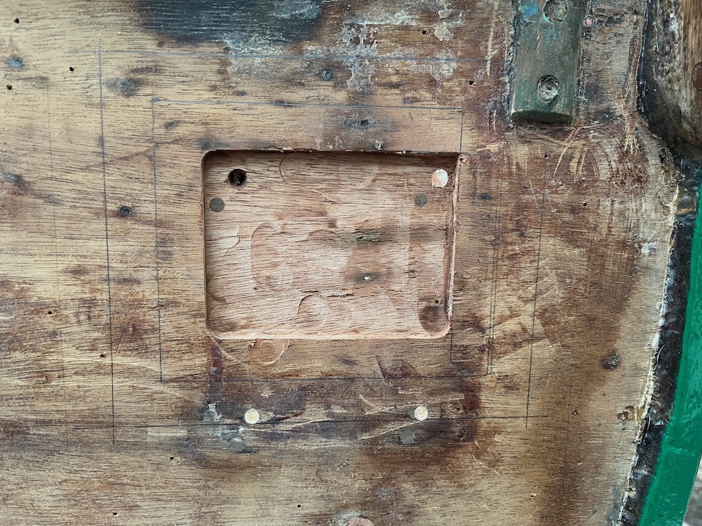
The shape of the graving piece is a slightly trapezoidal with two rounded corners and a prime candidate for the CNC Router.
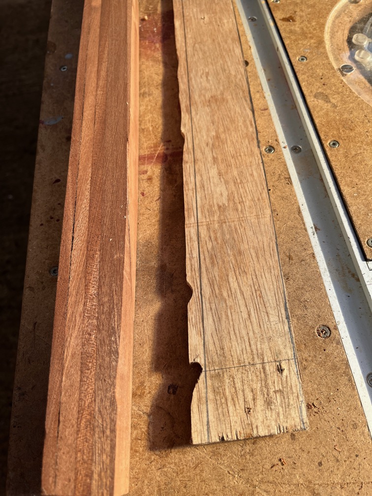
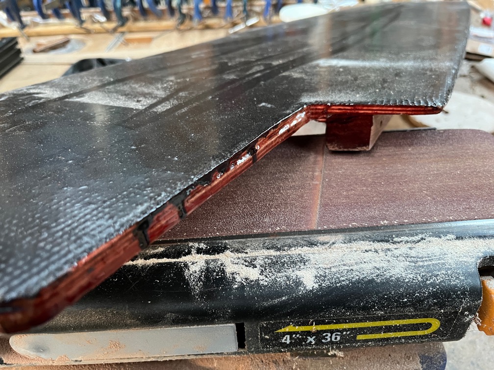
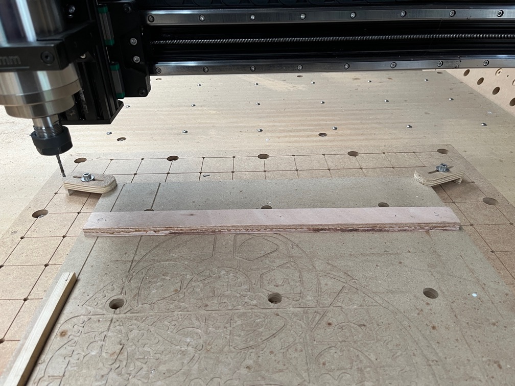
And it was, except for the first cut of the first pass where I didn’t clamp down the right hand end properly and the cut went completely awry. The the rest was good. I set it up so that it was fractionally too wide and then used the belt sander to bring it down to the correct size.
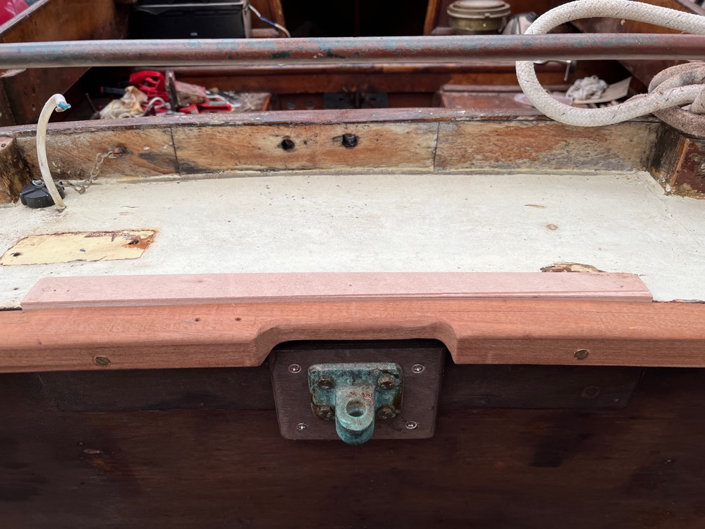
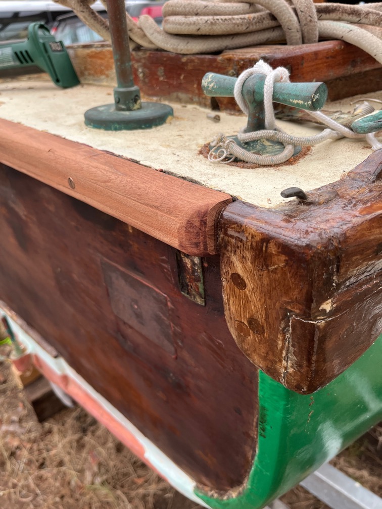
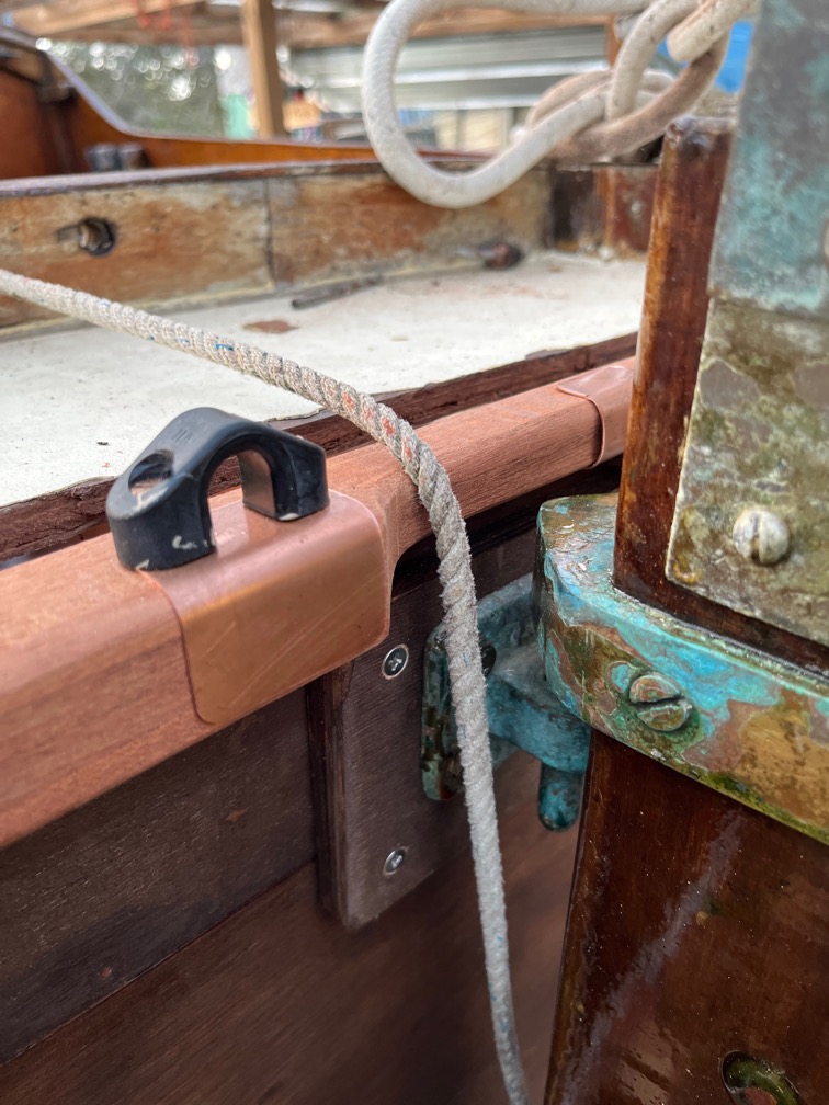
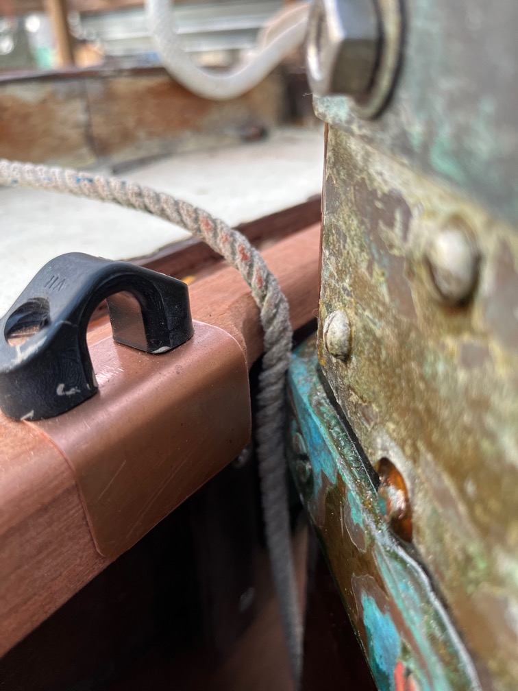
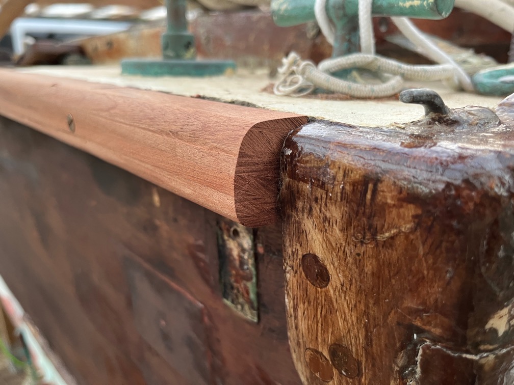
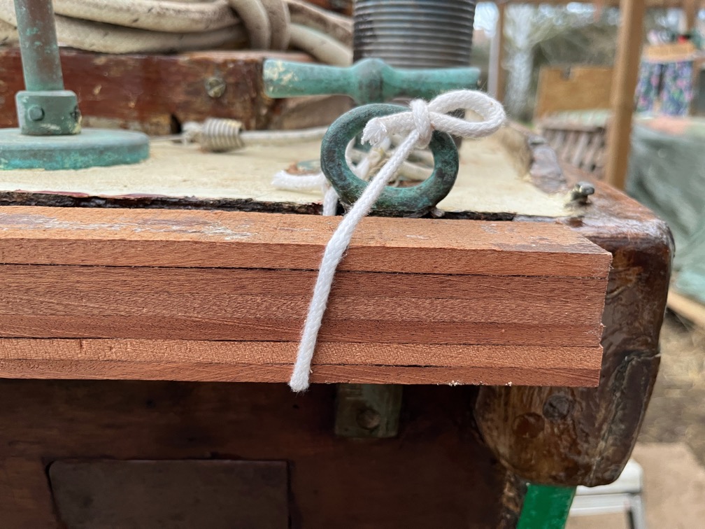
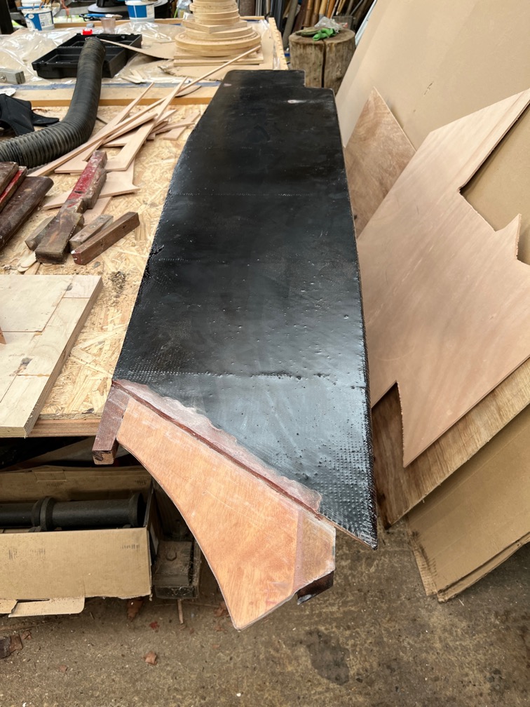
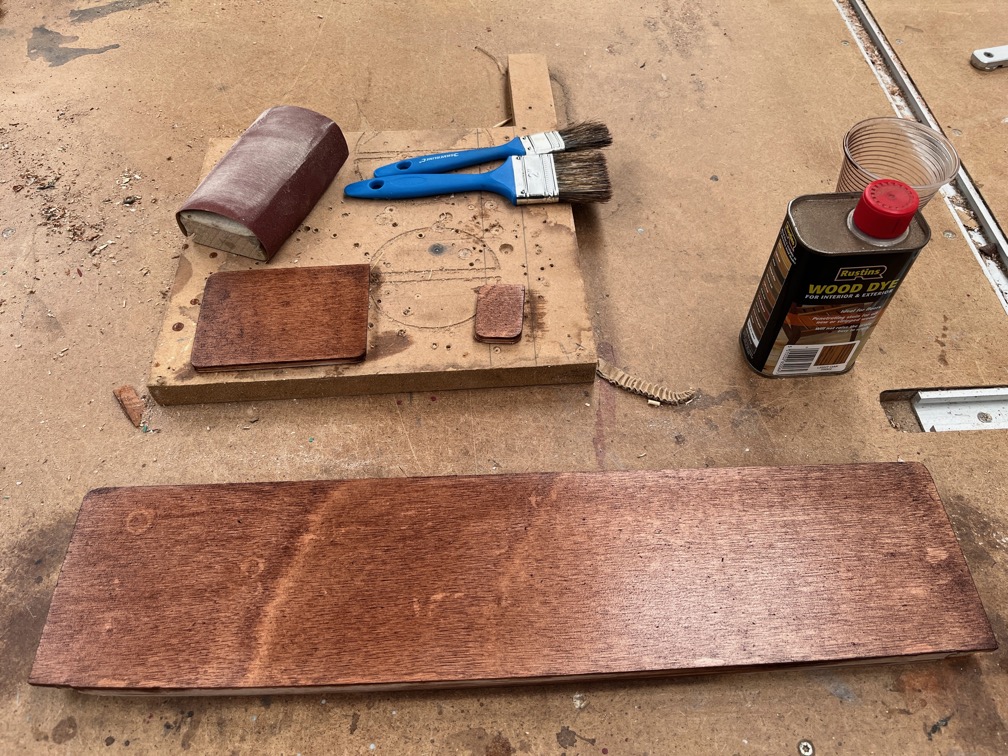
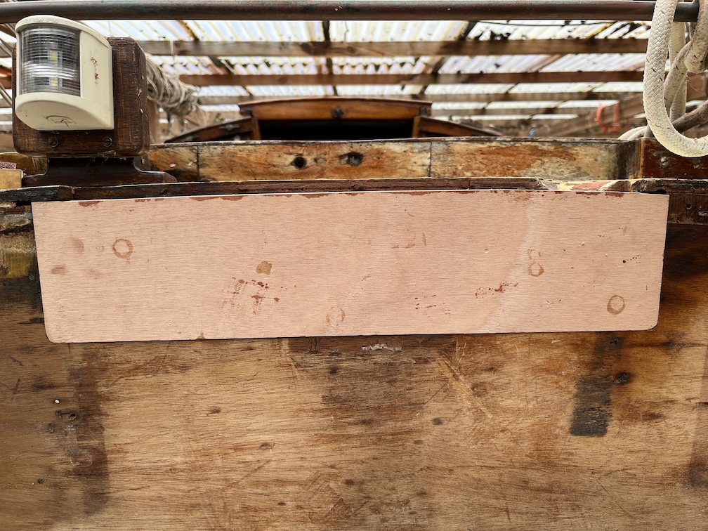
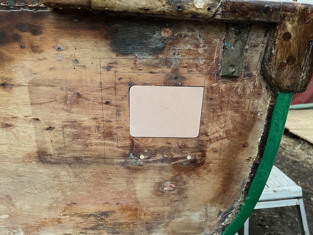
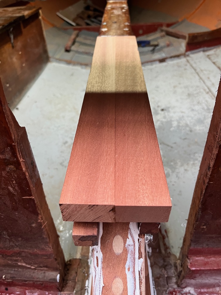
Like this. You’ll probably note that the graving piece is too high and that is because the original deck is 3/8″ or 9.5mm and the laminated graving piece is 12mm.
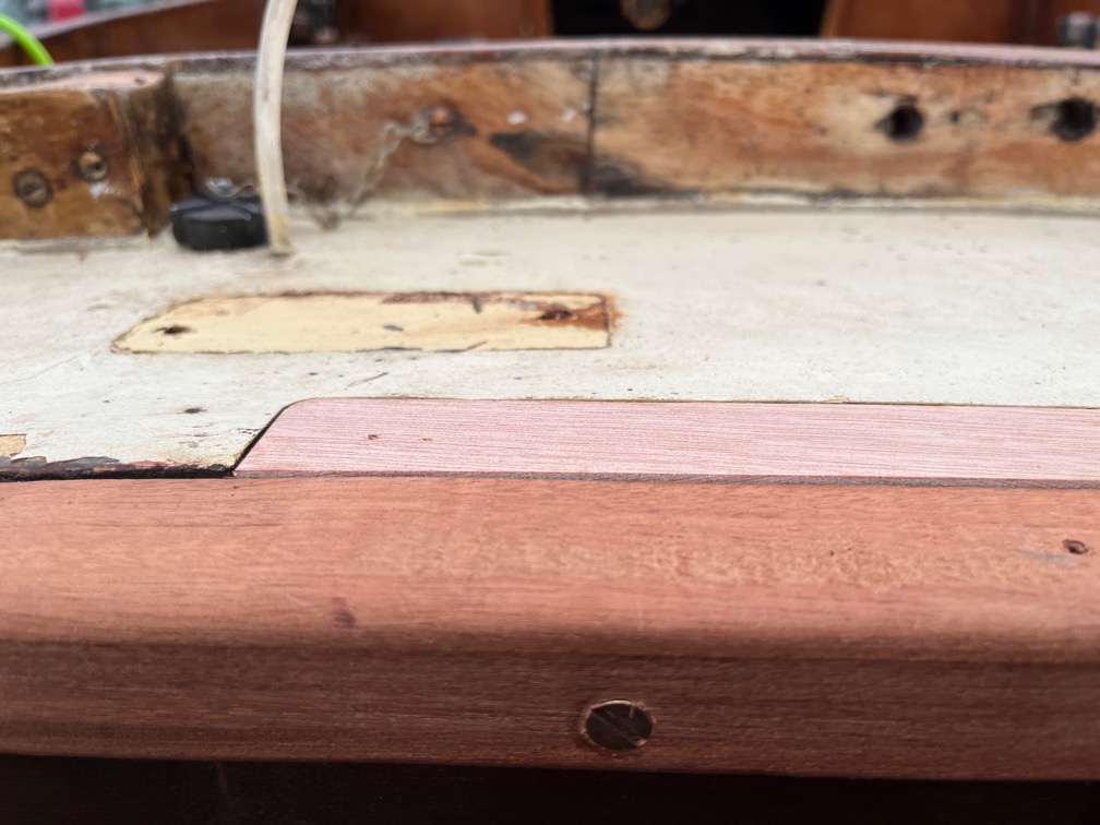
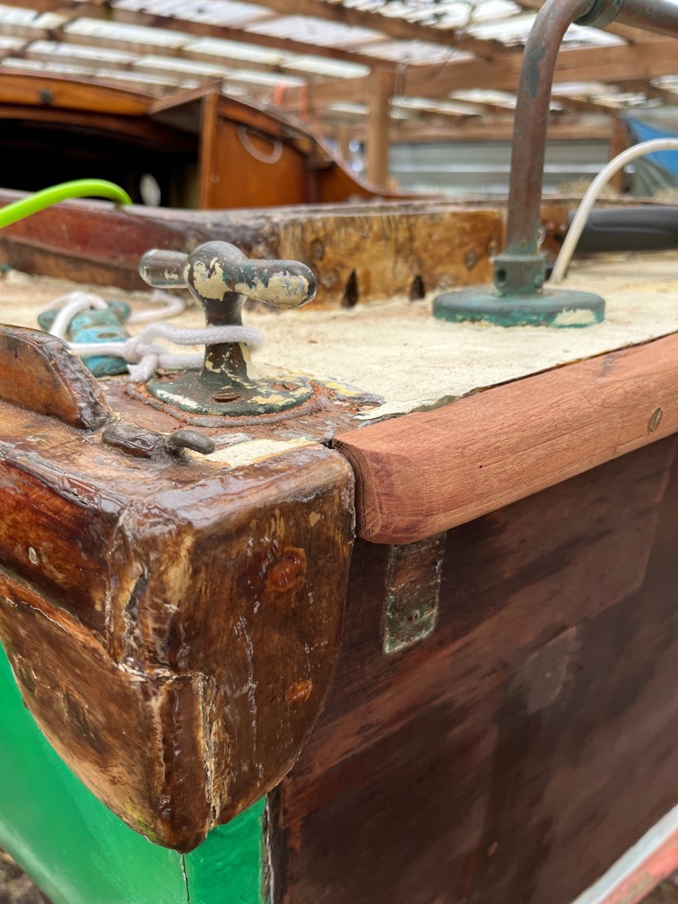
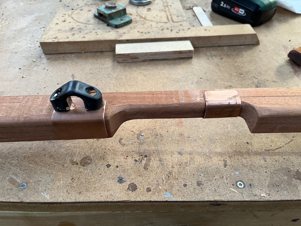
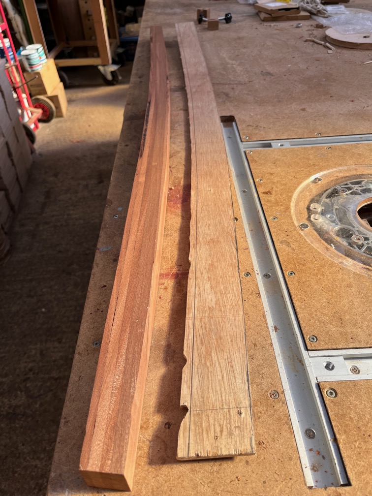
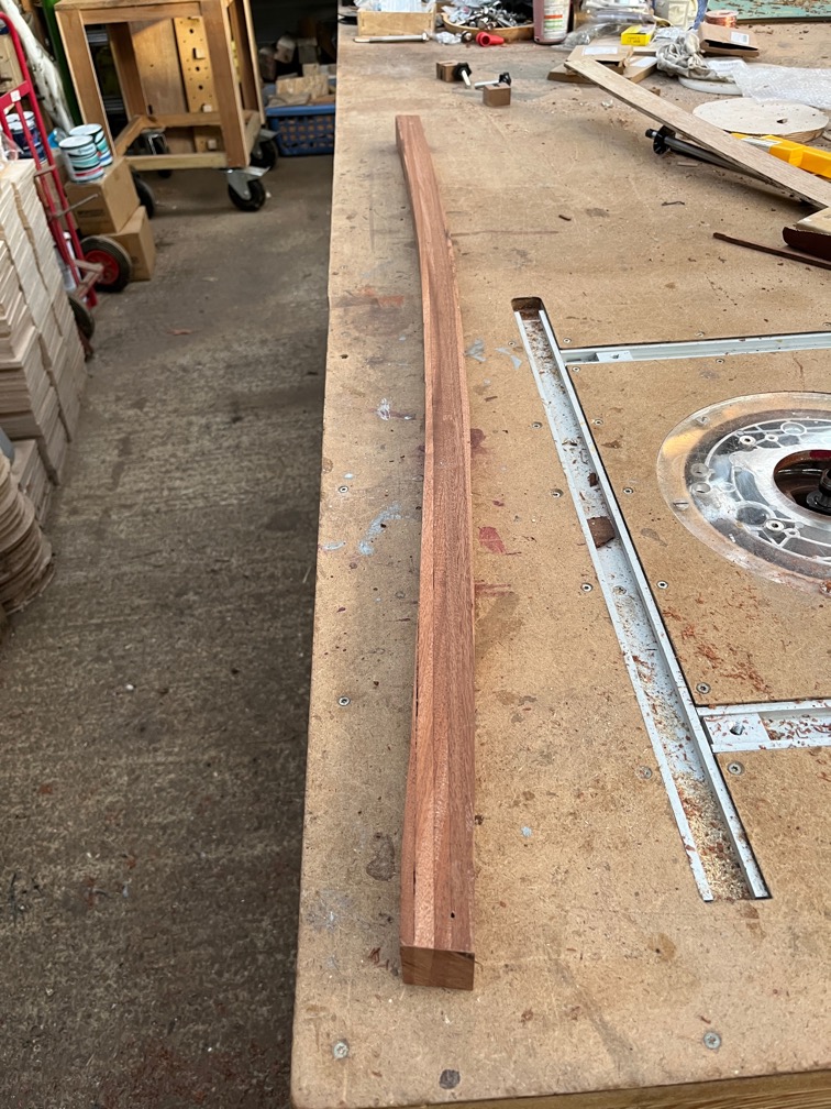
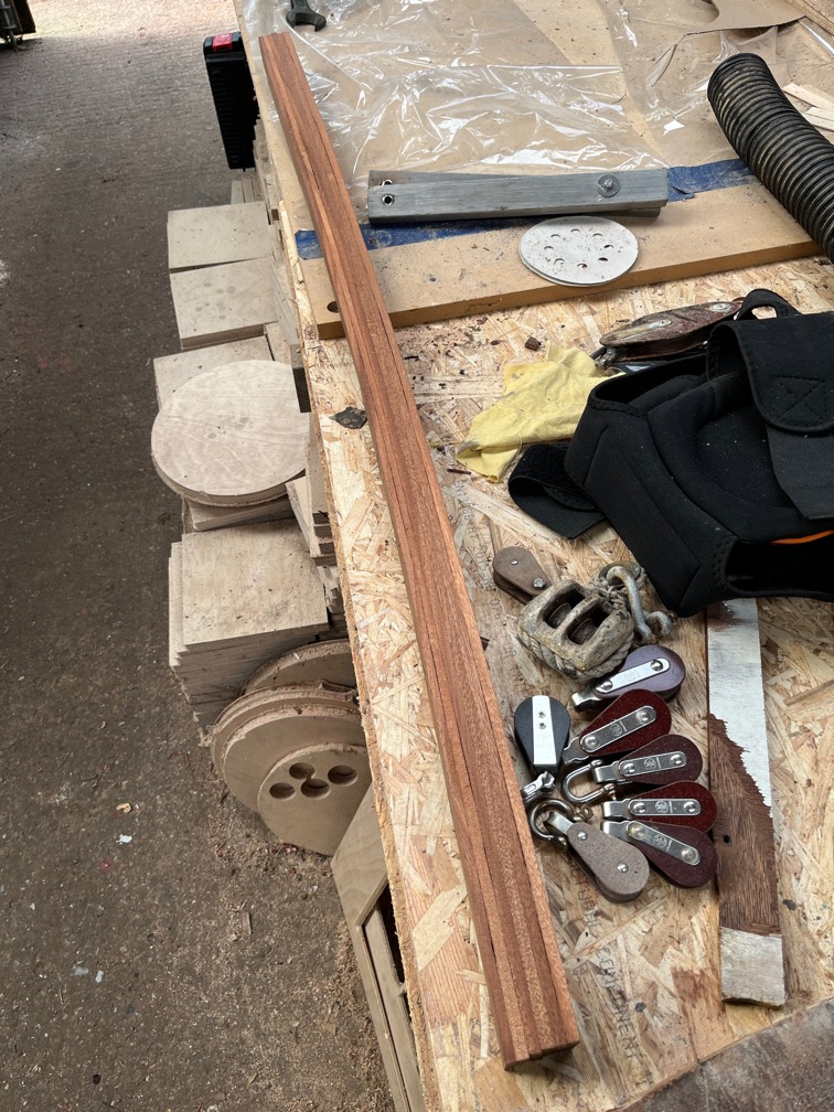
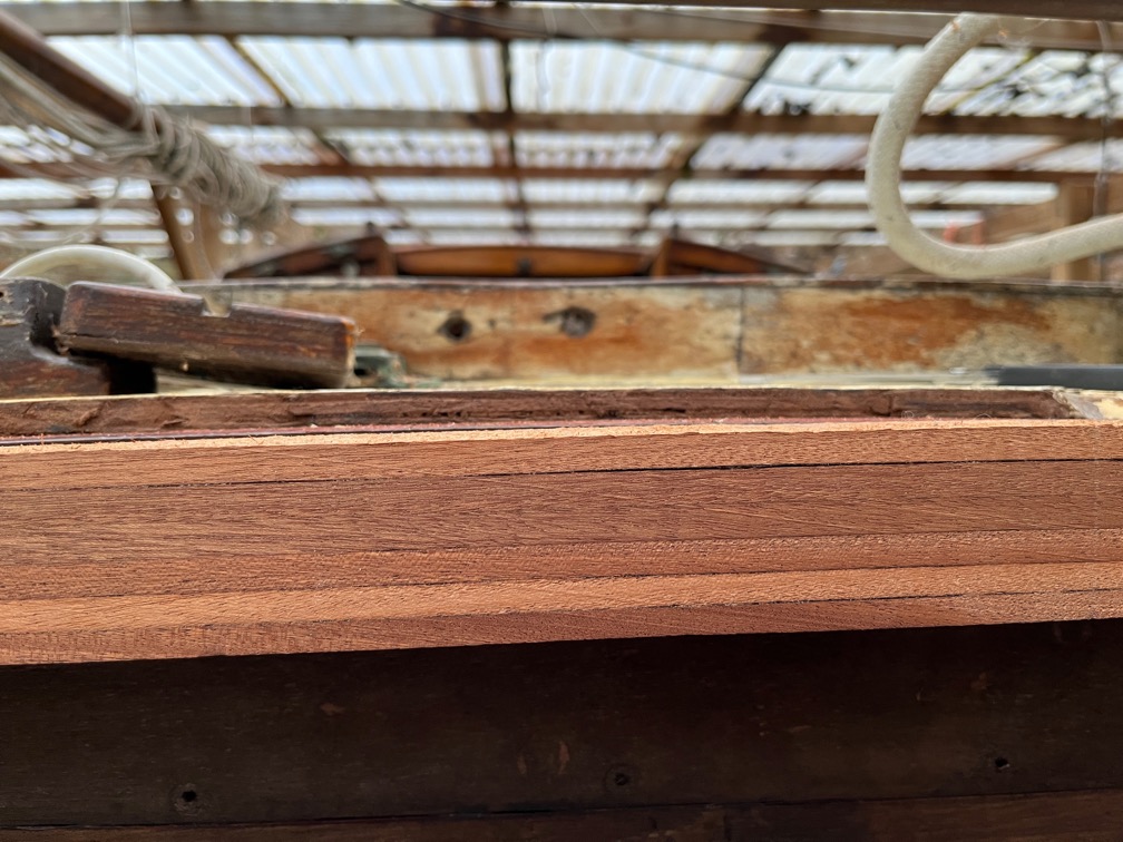
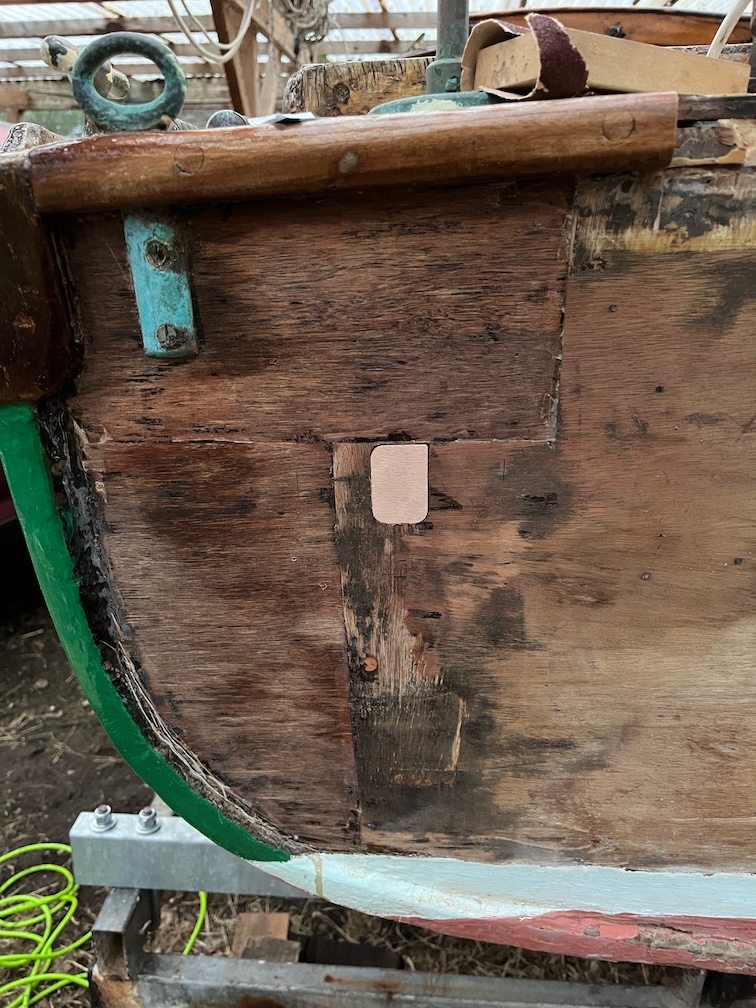
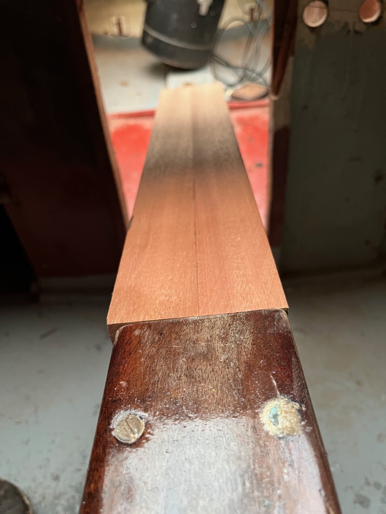
That did not take long to fix, a few passes through the planer and this is the result. This also planed off the errant first cut, so that is very good.
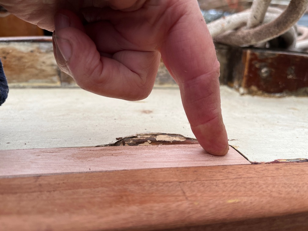
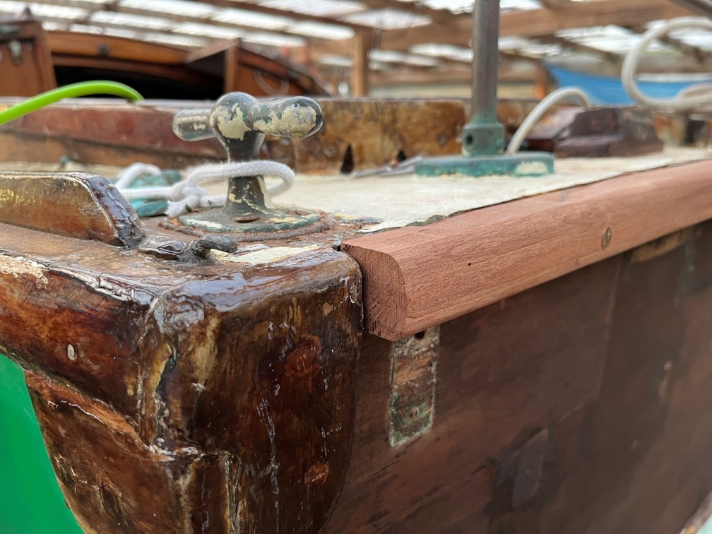
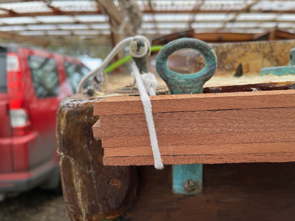
The other end is a good fit also. Because the curve is not quite correct, I had to hold it down, but that will be taken care of when it is glued in place.
For now, I need to go and warm my fingers up.
Time for a cup of tea.
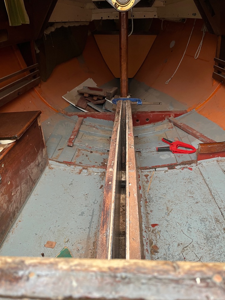
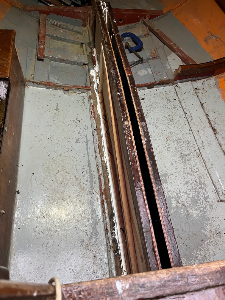
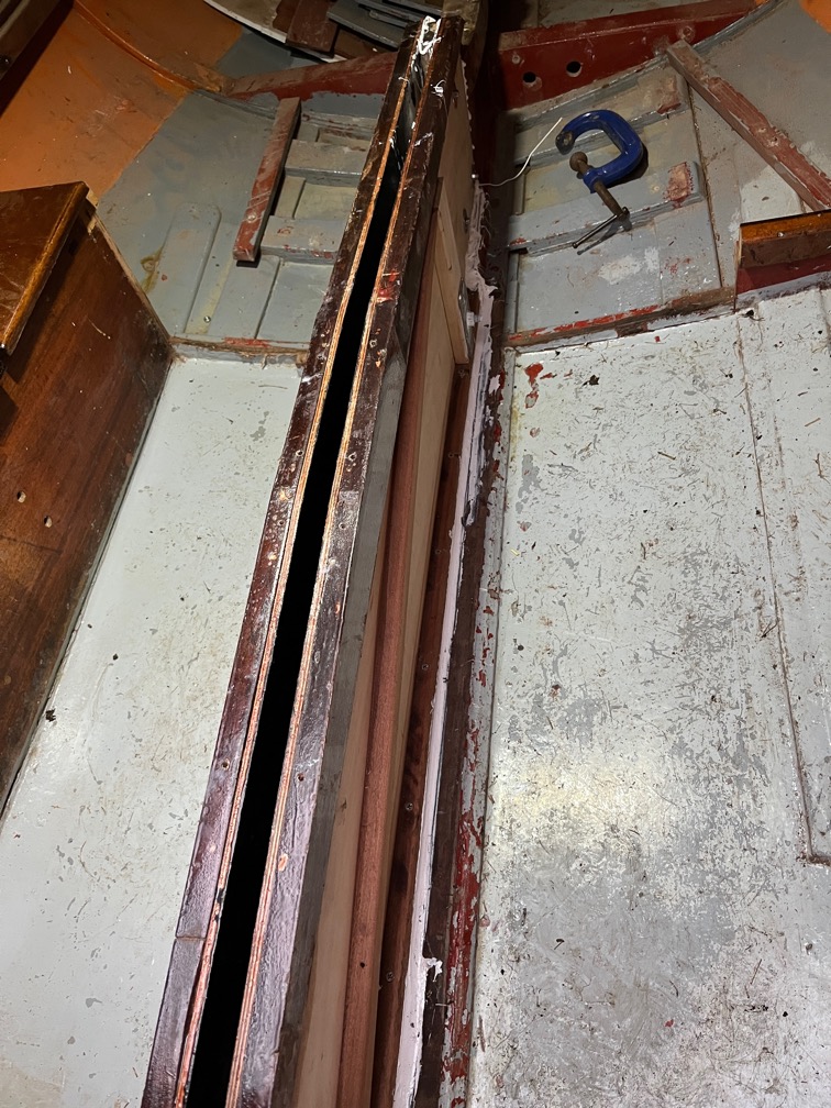
After lunch I spend the first part of the afternoon repeatedly dry fitting the case sides until the fit was about as perfect as I can get it. I also noted the places where I need to ensure that there is plenty of SikaFlex as the fit is not so good in those places.
It was a lot of up and down, rinse and repeat. By the time I took a break, my legs were aching. Still, the next task was to fit the case sides for real and they need to be done in one go so that when the bolts are tightened up, the sealant is still soft enough to squeeze out everywhere, filling all the gaps.
SikaFlex gets everywhere and is really sticky so I wasn’t able to get many on-the-go photos due to sealant on my hands. Well on the nitrile gloves, but you get the point.
Some time later…
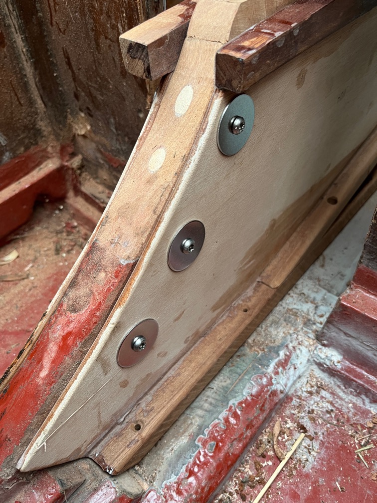
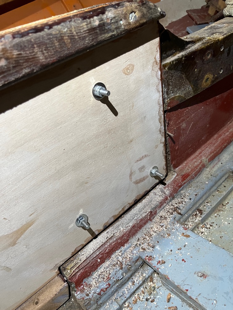
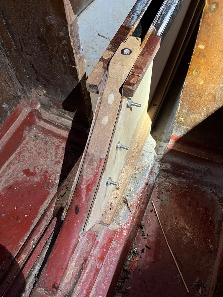
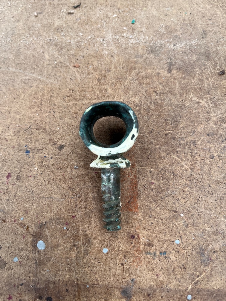
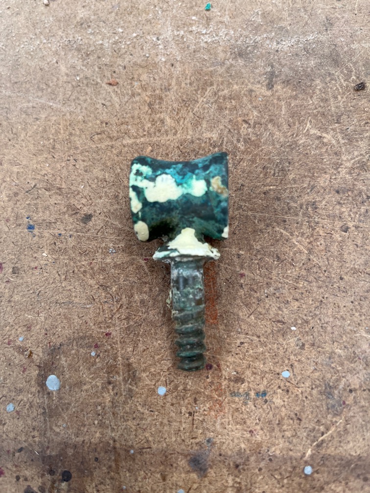
The final part of the dry fitting was to cut the bolts to length. You can see the very large washers in use here. Perhaps they are a bit too large, but that is not going to hurt.
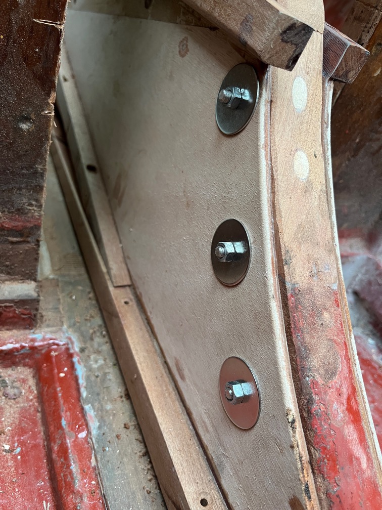
And the nut side of the bolts, although still not the correct ones yet.
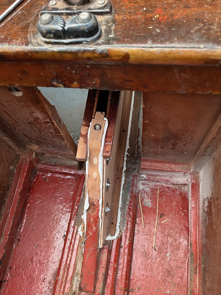
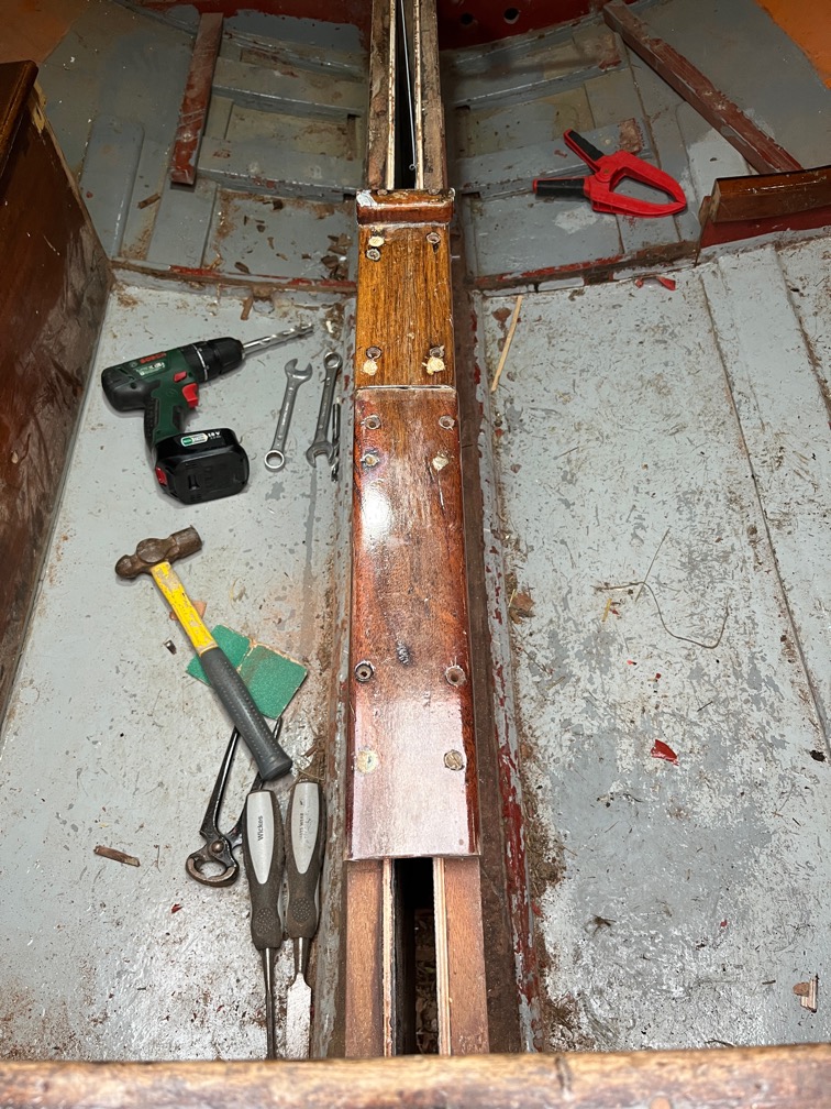
Third stage of the case side installation. The first stage was putting sealant on the parts of the sides that touch the keel. The second stage was putting sealant on the fore and aft blocks.
The bolts through the fore block have yet to be tightened.
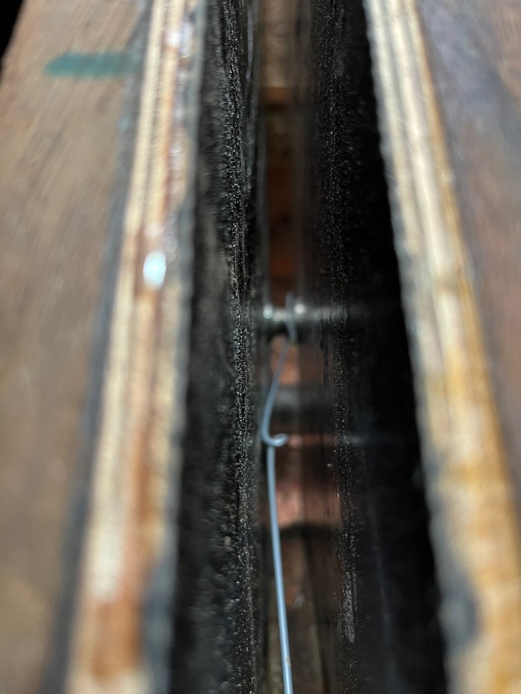
The screws are in through the bottom runners and into the keel and all parts of the squeeze out have been pressed over with the round ended stick, both to give a smooth finish and to ensure that sealant is pressed into any gaps.
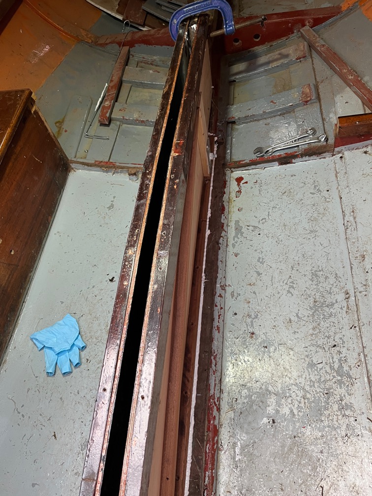
It looks a bit messy but trying to get a good finish when the sealant is sticky is an exercise in futility. I find it best to go over everything with the aforementioned round-ended stick and then let the sealant cure. After that the stringy bits can be cut away with a knife or a chisel and the whole lot sanded if required.
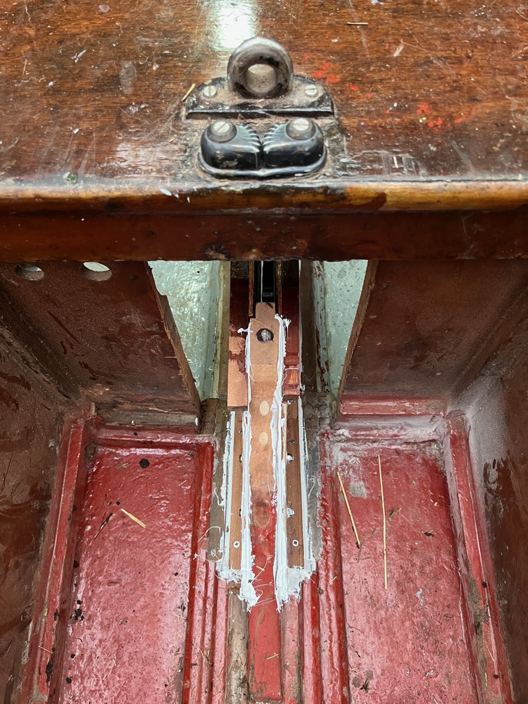
This bit is especially messy.
Still, the centerplate case sides are now in awaiting the next major task and that is the leak test.
For now, I’m knackered.
Time for a cup of tea.
Once I had rested for a while I decided to do a bit more.
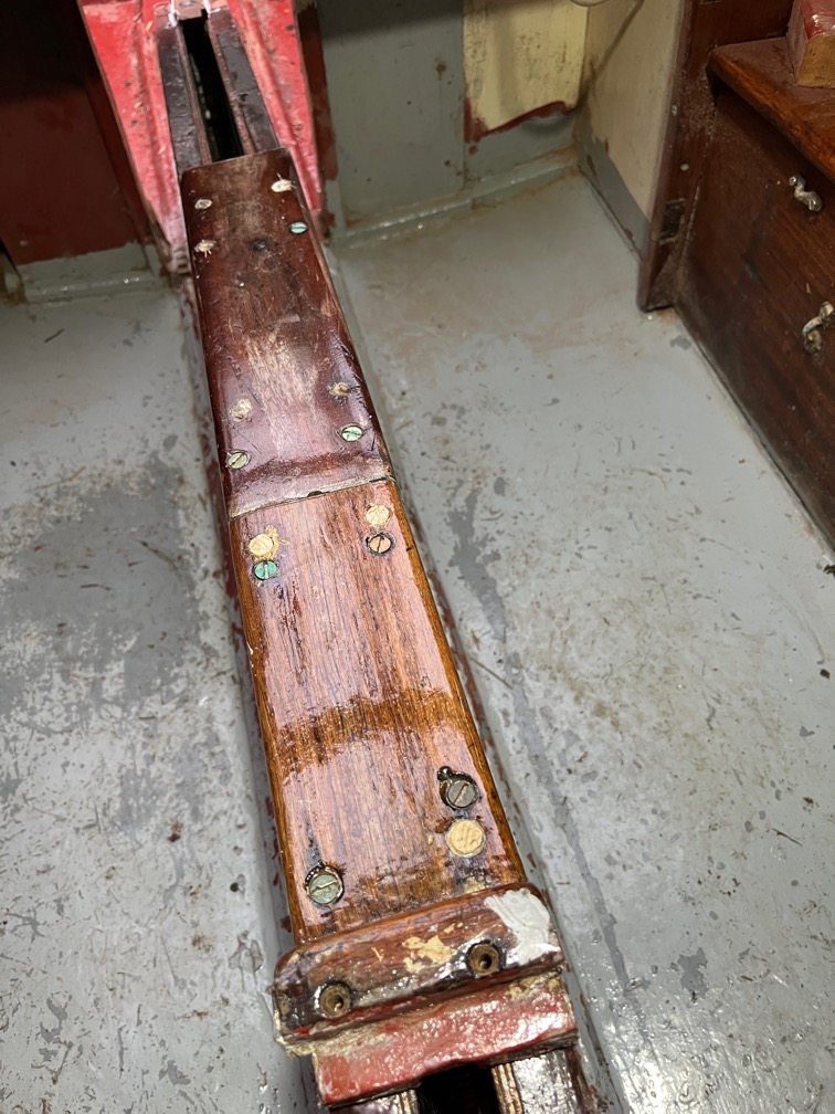
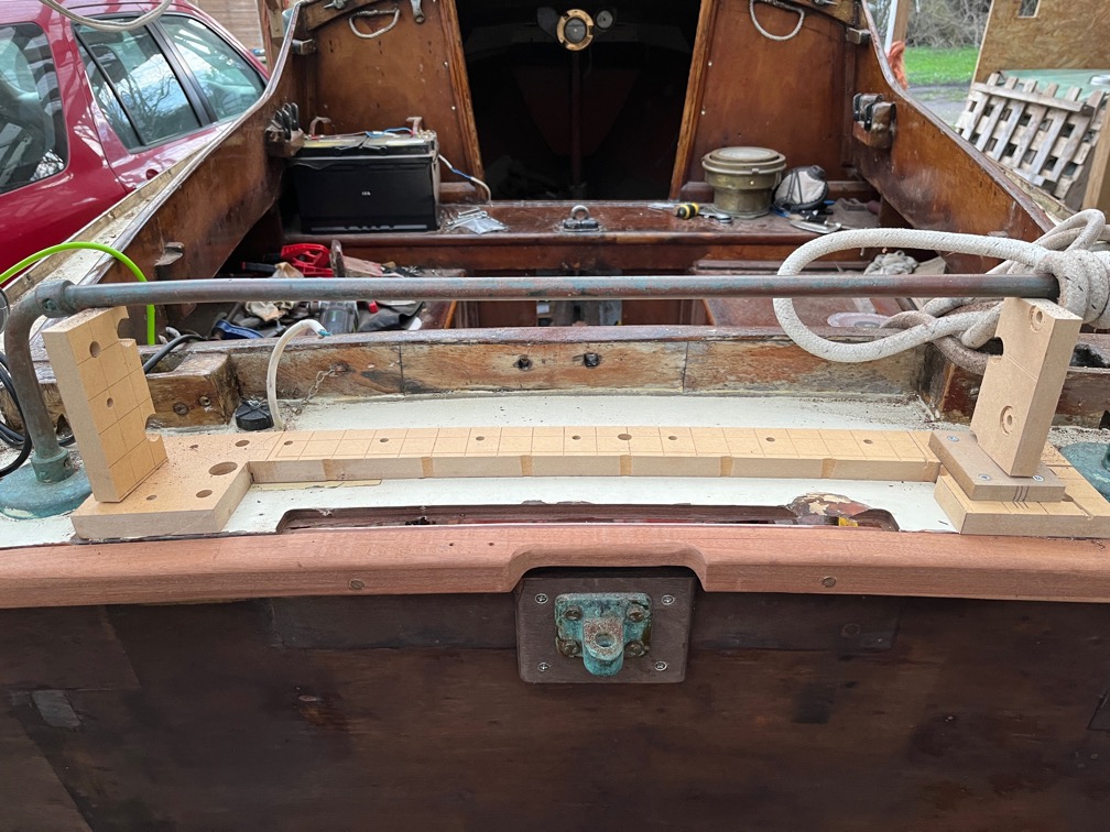
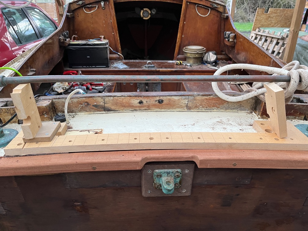
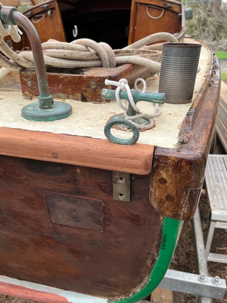
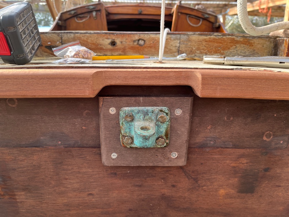
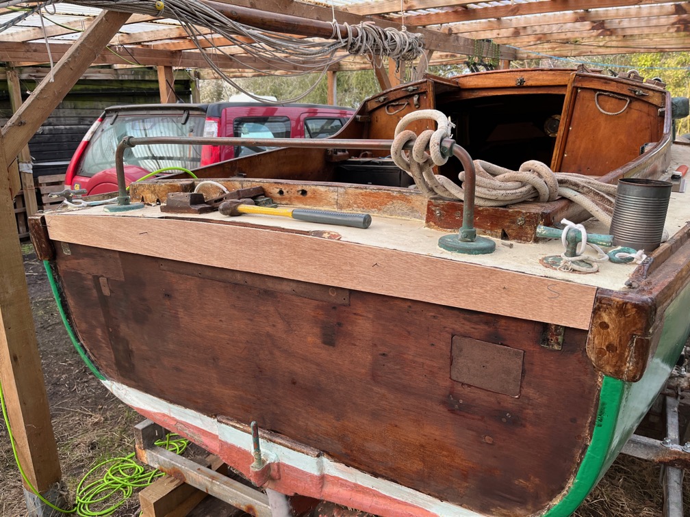
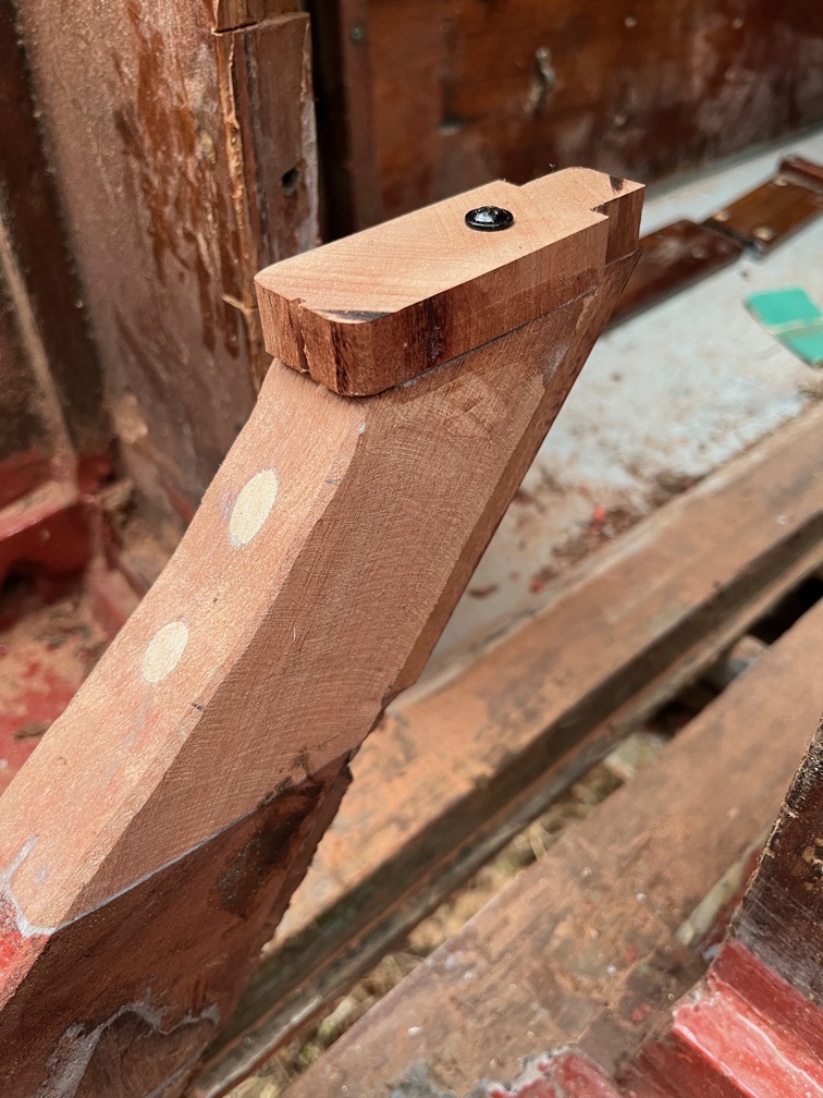
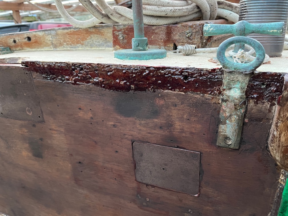
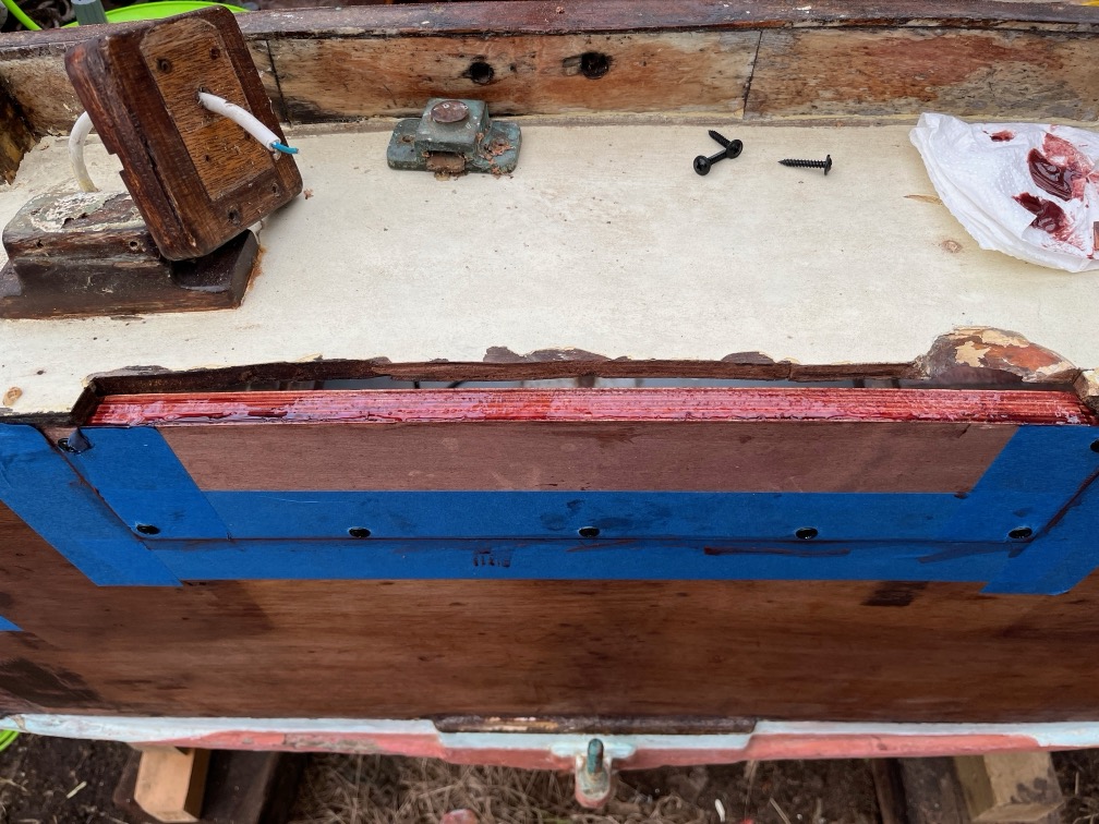
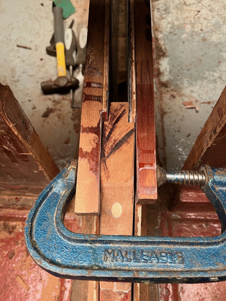
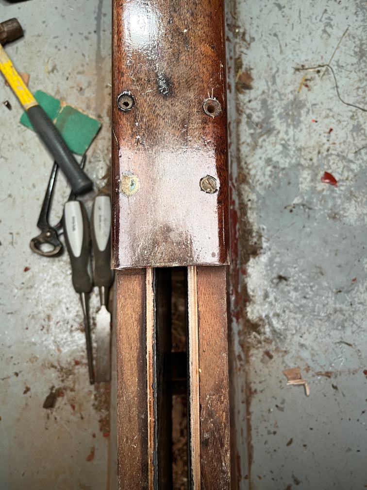
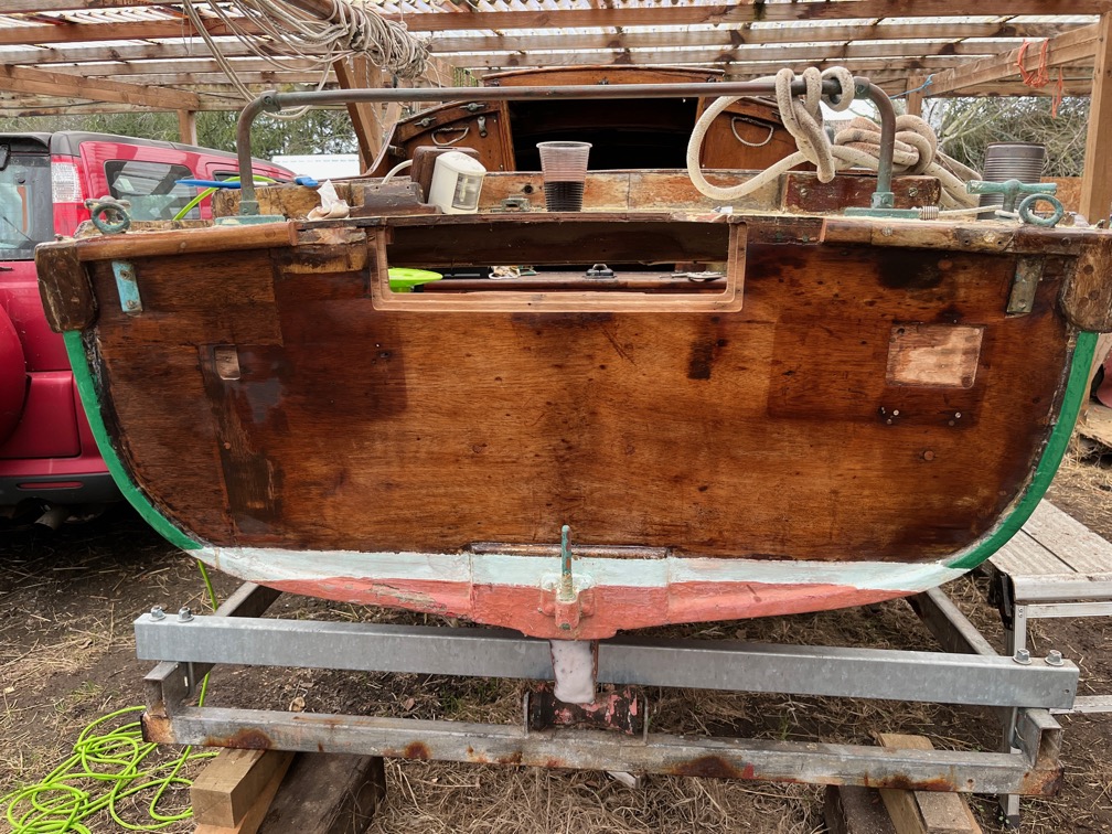
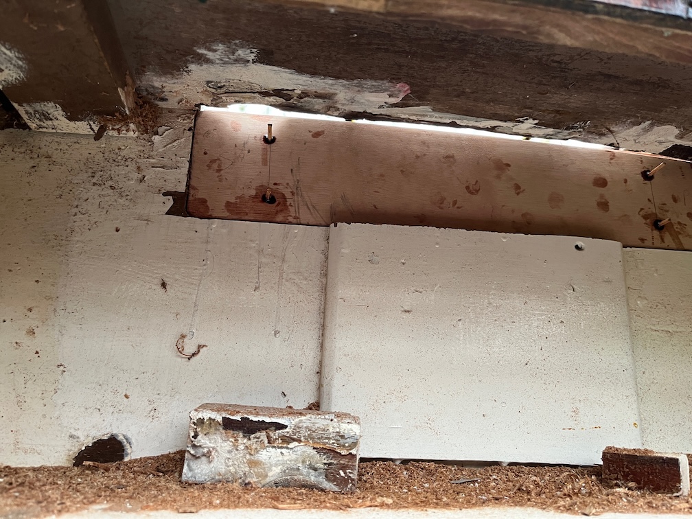
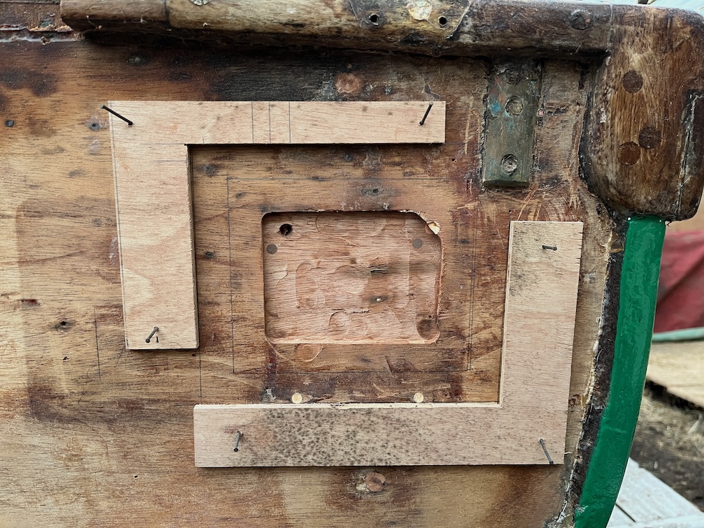
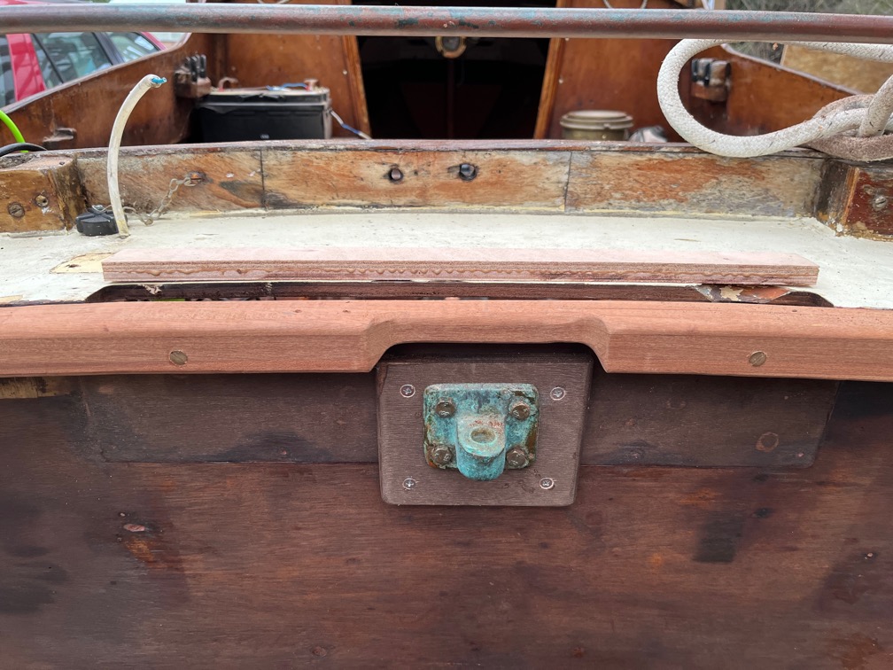
It is quite nice to find that things are going well when original pieces of the centerplate case fit back where they belong without having to modify anything. There the two intact top pieces of the case are screwed back on using the same screws in the same holes. The fact that it all fits indicates that my rebuilding of the case isn’t far off being correct.
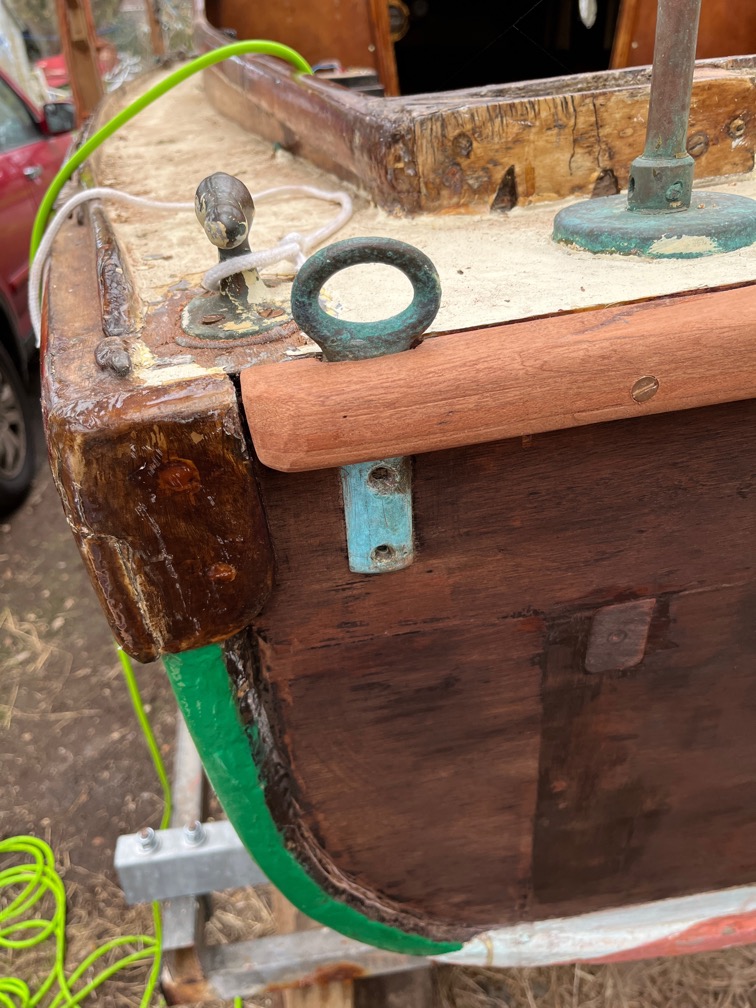
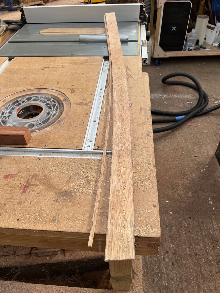
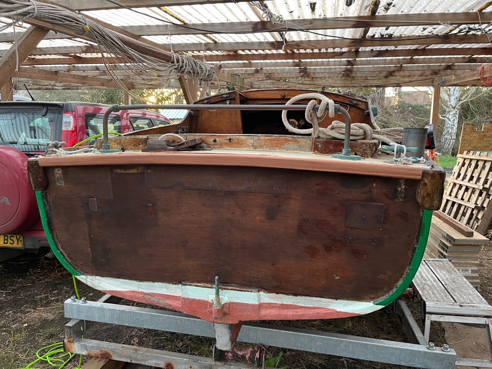
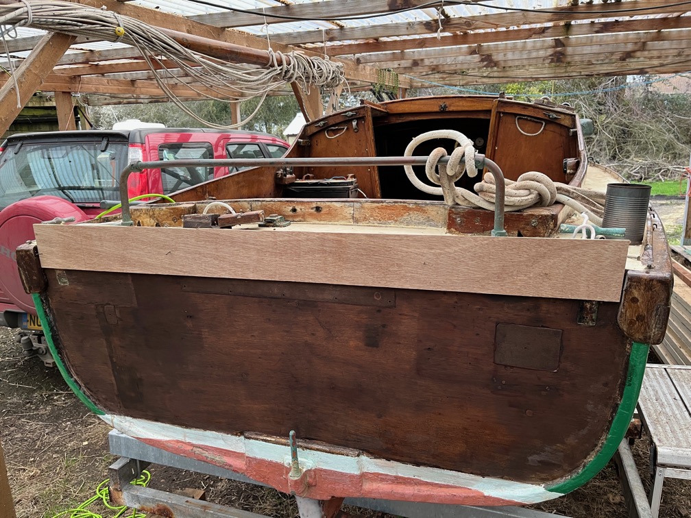
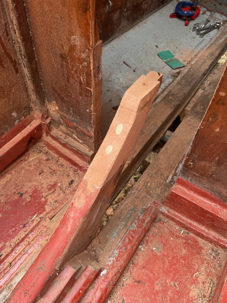
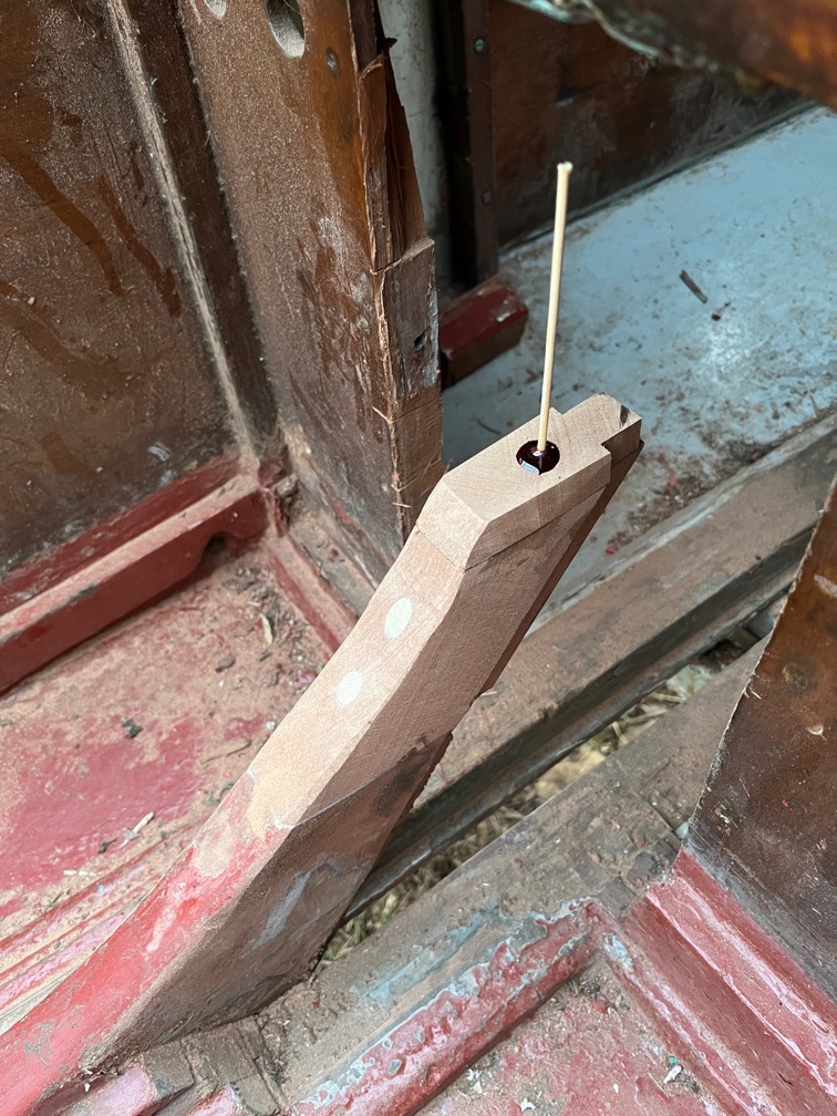
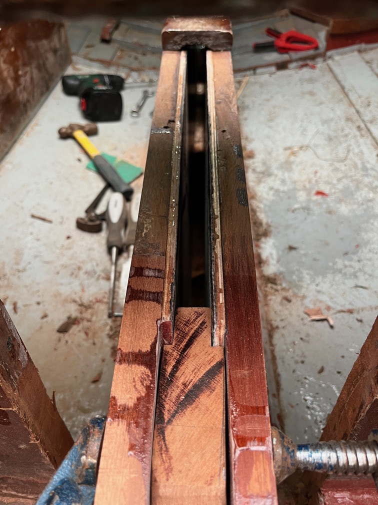
The piece of timber that is going to be the replacement for the top that had to be cut away was put in place, more or less, to check that I had the dimensions correct.
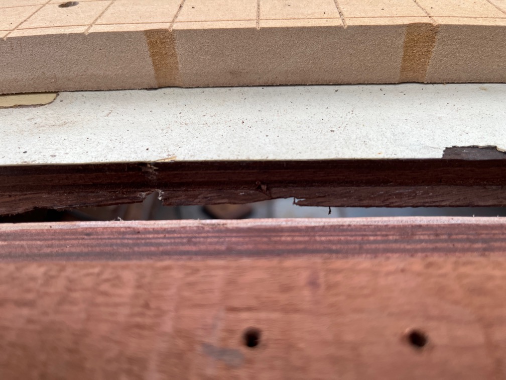
As you can see, it is slightly wider and longer than required which is good. Once the aft block has been sanded to shape I can make the noew top piece.
Time for a cup of tea.