One of the reasons for working on the nav lights these last few days was to answer two questions.
Firstly, If a reflector was fitted inside the nav light would that affect the light cone emitted from the light and if so, by how much?
Secondly, how much brighter would a reflector make?
There was an additional question of whether the LED replacement bulbs affected the cone of light emitted as compared to the original incandescent bulb. This one was largely academic since I’m certainly going to use LED bulbs, but it will be interesting to see if there is a difference.
I asked on the Dinghy Cruising Association website for possible ways to add a reflector to an antique nav light and the two best options seemed to be scrunched up aluminium foil and an acrylic based mirror cut to shape.
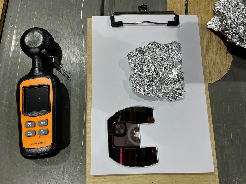
Once darkness had fallen I went back out to Shoal Waters armed with a torch, a piece of scrunched up foil, a carefully cut mirror and a light meter.
I then spend half an hour or so taking a series of measurements of the light output of the starboard nav light. Firstly without any reflector, then the foil and finally the mirror. I placed a wooden block on the side deck and used that to ensure that the position of the light meter was the same for each measurement.
Not surprisingly, the readings for the light without the reflector was the lowest, as I expected, but the question was which of the reflectors was better. The foil didn’t reflect as much light as the mirror, but because of the scrunched up nature, the foil spread the reflections around a lot more than the mirror. Also, not surprisingly, the mirror reflected the most light but this was not as widely spread as the foil.
The foil was 8% brighter on average whilst the mirror was 25% brighter on average than the light without any reflector.
So which is better? It depends. The foil is 8% brighter across a broader spread but the mirror reflects a lot more light.
As any maker will tell you, we spend more time making jigs than making projects, or so it seems at times. Take the new brass thumb screws I bought for the navigation lights. There were two small problems with them. The first is that they are brass. Nothing I can do about that as those are the only ones that fit. The second issue is that they are flat on the head, no slot for a screwdriver. Now that is something I can do something about.
The first, and most obvious answer, is to cut a slot with a hacksaw, but if you’ve ever tried doing this you will know that the result is usually less than optimal.
Enter a jig.
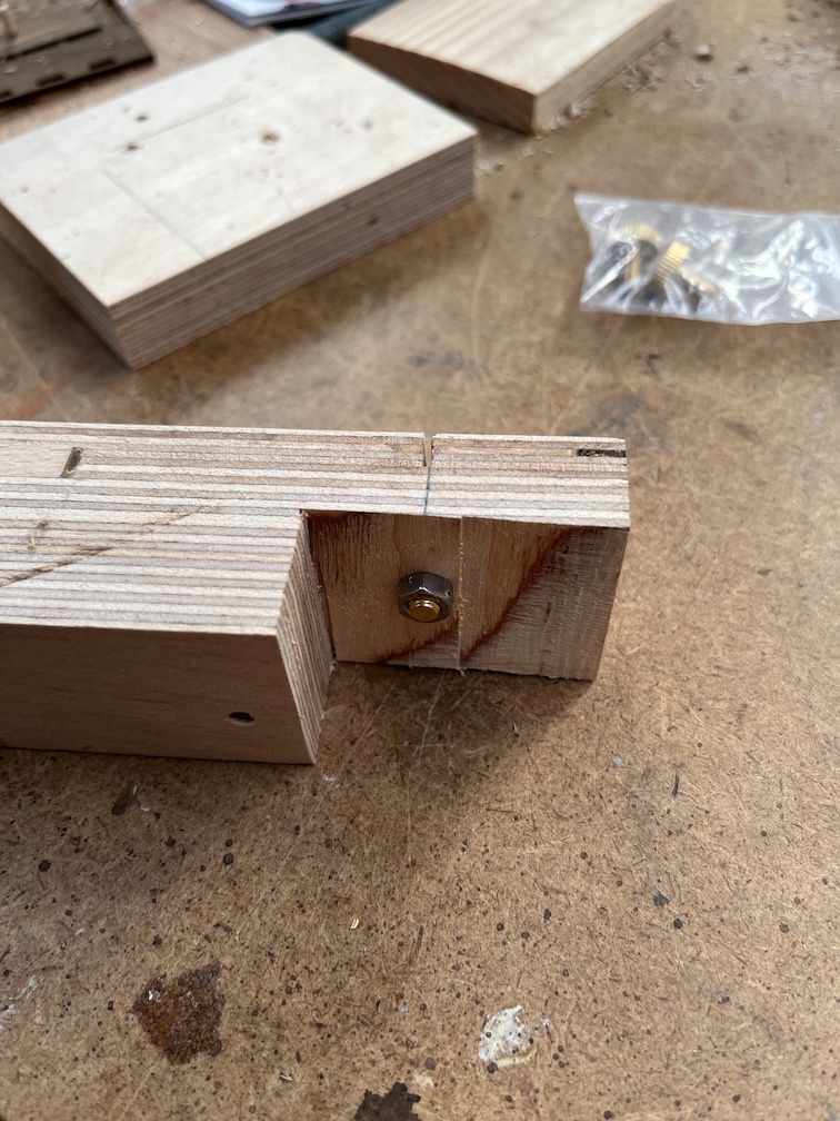
I cut a 5.5mm holes through a piece of scrap plywood and then a 12mm hole halfway through centred on the smaller hole. I marked a centreline and use the bandsaw to cut a slot in the wood through the centre of the larger hole. The thumbscrew was put into the jig and fixed in place with a nut on the bottom.
Like this.
I then used the bandsaw again to cut a small slot in the thumb screw, just to get the slot started and to stop the hacksaw blade from wandering.
Over to the bench vice next and with the jig clamped in place, I used the jigsaw to carefully cut the slot to the required depth using the cut in the plywood as a guide.
The result is a nearly perfect slot in the top of the thumbscrews. Marvellous.
The newly slotted thumb screw in place. Apart from the obvious newness of the brass, it looks pretty good. I’d say that was a good use of my lunch break.
Having had another cup of tea and a sit down, I decided that since the screws had arrived I would continue the work on the nav lights.
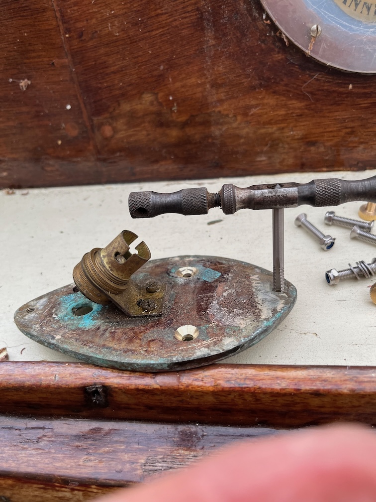
The new brass thumb screws are metric, M5 to be exact, whereas the older ones, probably over 50 years old, are imperial. No idea what they are but they are smaller than M5 and the new thumb screws are too large to fit in the original holes. This means that I need to tap the existing holes to take an M5 thread. I gathered the parts together and set to.
The imperial hole was wide enough to use the M5 tap directly and did not need to be drilled out. The new thread didn’t take long to make, the initial thread or two always being the hardest to get right.
The new thumb screw was inserted to make sure that it fit, and, as you can see, it did.
Next the new countersunk machine screws were used to attach the base plate back to the cabin side. I used normal nuts to do this as the work is not completed as yet. I’ll need to take the plate off and on again a few times before the final fitting and at that time I shall use self-locking nuts. Still, for now, this is looking good.
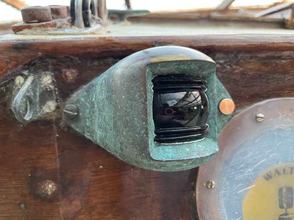
Finally, the outer housing was screwed in place. Looks pretty good. With this successfully completed I carried out the same process on the other side.
The brass thumb screws will need to have a slot made in the head to allow it to be tightened with a screwdriver as the head is a very tight fit into the recess in the housing, but this was expected. I’ll use two of the spares to make the slots, either using the CNC router or a hacksaw.
All in all, a very productive day and although the tasks I have done today are quite small ones, I feel as though I am making progress.
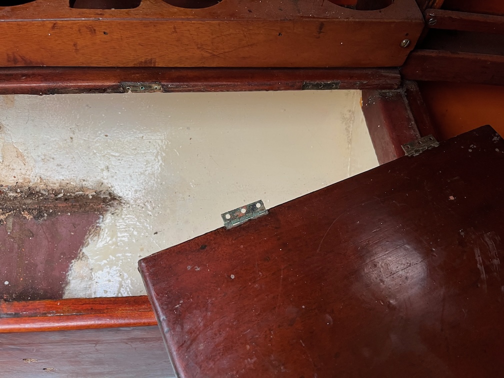
Having had a cup of tea and a sit down, I decided to tackle the locker hinges and the old gas bottle box.
As it turned out, three of the six screws to be removed came out easily, the screws being in quite good condition despite being brass. The other three, those on the aft-most hinge, snapped as they were unscrewed, but the locker lid came off easily even so.
Emboldened by that success I turned my attention to the six screws holding the box to the side panel.
These came out fairly easily but only after being persuaded. In this case that meant putting a screwdriver into the slot and then hitting the end of the screwdriver with a hammer. Not too hard, but hard enough to break any seal between the screw itself and the wood. That’s the theory, at least. In this case it worked.
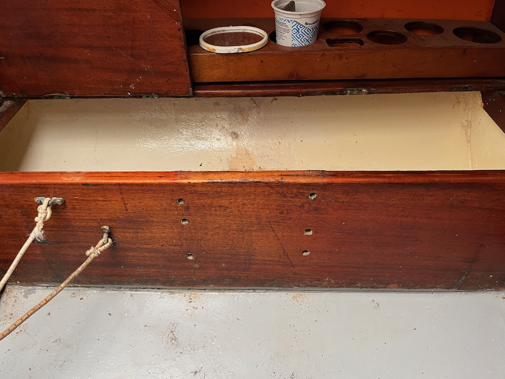
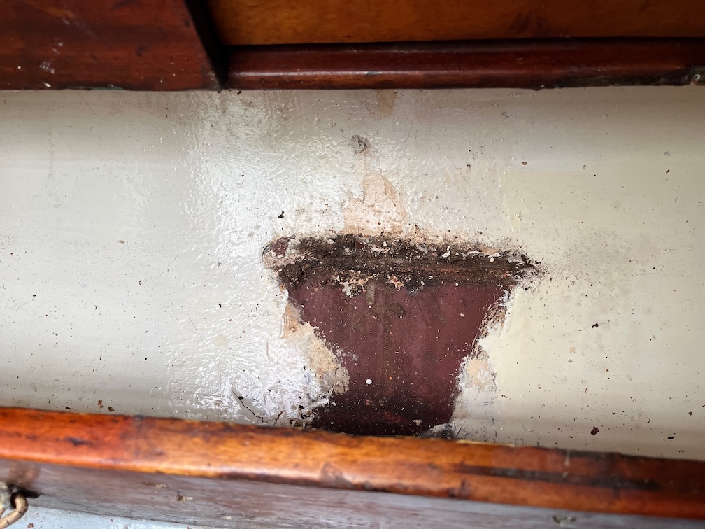
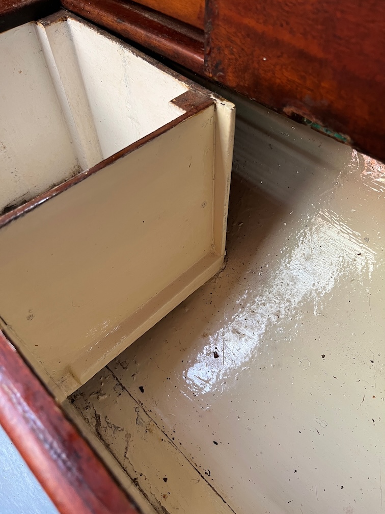
After the box was removed, you can see that the white paint on the hull was done after the box had been installed. It was fairly clean in the lockers, which was nice to see.
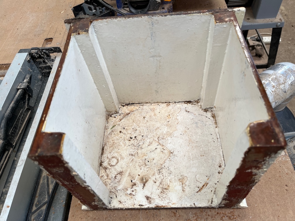
The box itself was taken into the workshop with the intent of reusing the wood, but all the brass screws have distigrated so I’ll have to put some thought into getting those out without damaging the wood too much.
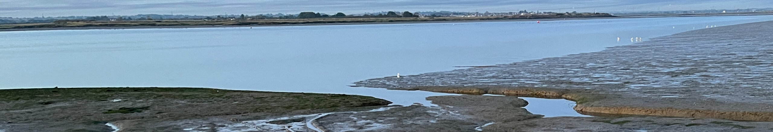
The stove in Shoal Waters was, for many years, a single burner screwed into a Camping Gaz cylinder. The burner could be replaced by a radiant heater to heat the cabin when cold.
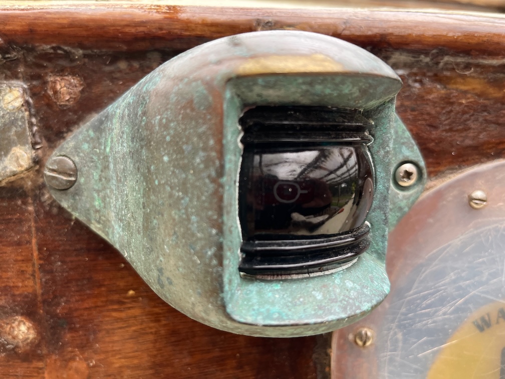
The stove can be seen in the above photo, the cylinder housed in a well between two lockers on the port side of the cabin as is traditional.
To use the radiant heater the stove part was unscrewed, the cylinder moved to sit on the cabin floor between the lockers and the centreboard case and held in place with a bungee. The heater was then screwed onto the cylinder.
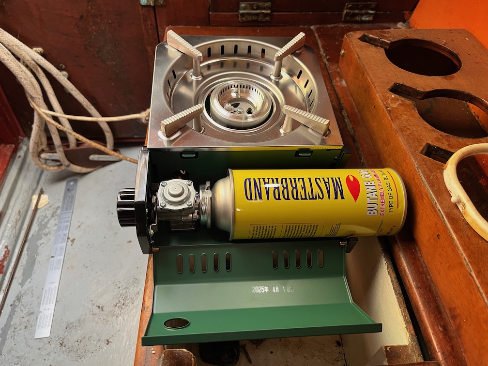
Now, none of these parts were on Shoal Waters when purchased and I’m not going to replace the stove with an exact replacement. Instead I’m going to use a burner that takes the modern 200g canisters since this will allow me to store the spares outside of the cabin. However, the space available for such a burner is quite small and the size I use for camping is too large.
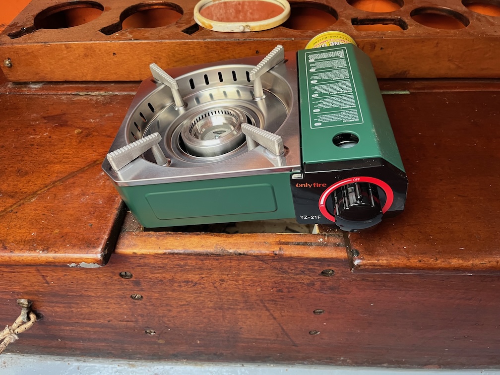
Not to worry, a quick internet search found a much smaller unit.
The difference between this and the larger, more common variant, is that there is no lever mechanism to pull the canister into place. Instead it is held in place by a magnet.
Now, my intention is to make a box to hold the stove that is just a little bit deeper than the stove plus canister, so that the canister cannot move away from the magnet which might happen in a bumpy sea.
The stove is also a bit wider that the space that held the old gas cylinder and that will mean rearranging the lockers slightly.
The stove plus canister is also a bit deeper that the locker, as you can see here.
However, the gas cylinder locker is a simple box screwed to the side wall, so making it wider and deeper will not be too much of a chore. The hardest part will be removing the lid of the locker forward of the burner to cut a section off to make space for the wider burner box.
I started looking at the navigation lights as I need something small to be getting on with since I have hurt my right foot. When I get tired I make mistakes and last week the mistake involved the foot and a solid metal support meeting at a high enough relative velocity to break open the wound remaining from the surgery a few months ago. So, no kneeling down on the inside of the boat trying to work on the centreboard case. I’ll have to wait until I can comfortably flex the foot before continuing with that.
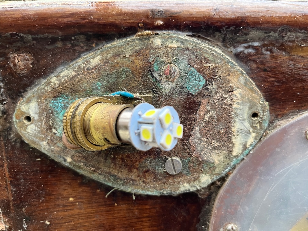
One of the things I’ve done as part of the refurbishment is to buy LED replacement bulbs for the lights to cut down on battery drain.
This is the original bulb, fairly standard.
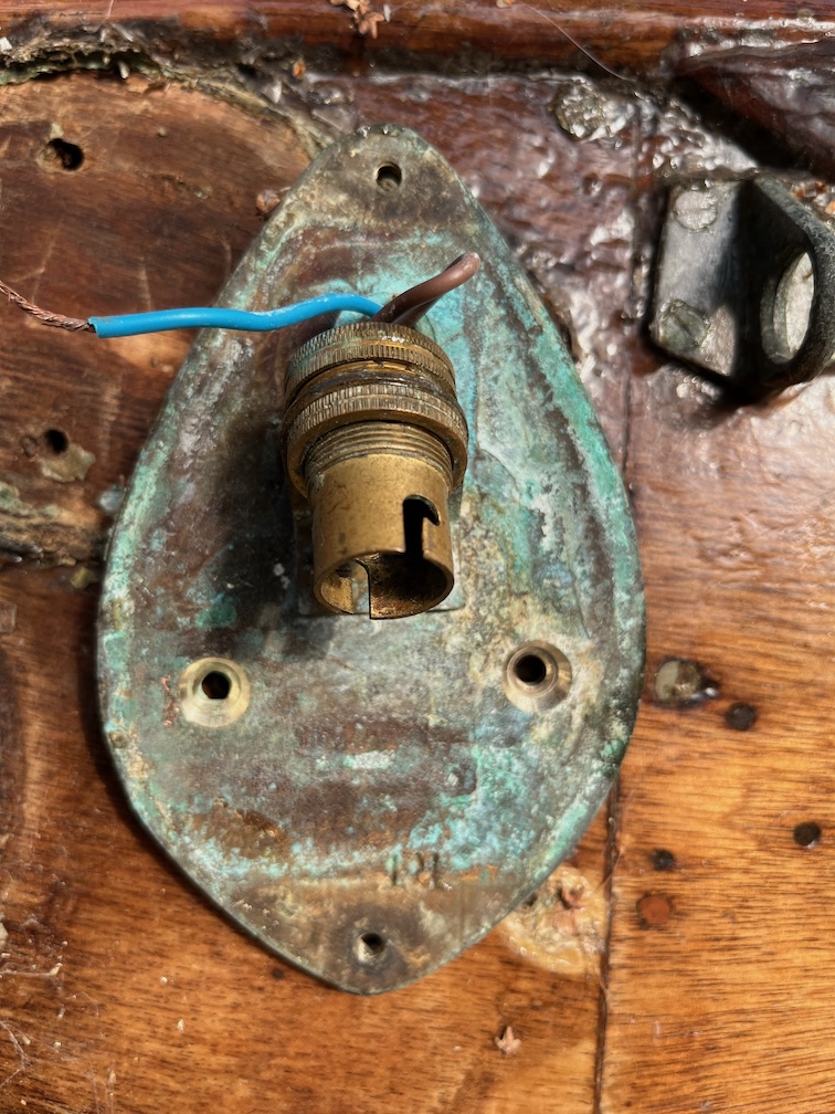
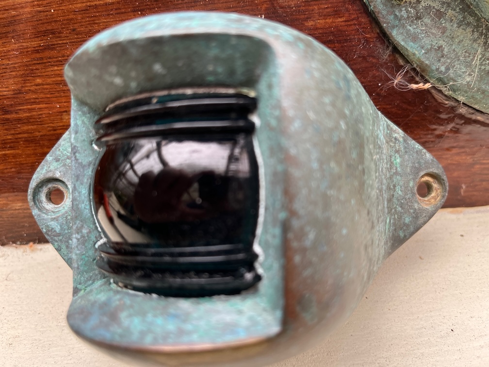
And this is the new LED bulb. It occured to me that the back of the light, as you can clearly see from the photo, is not at all reflective and thus the nav lights will be dimmer than they could be. I asked on the Dinghy Cruising Club Forum, of which I am a member, for suggestions and these boiled down to two main options. Crumpled aluminium foil and a plastic mirror cut to shape, both of which are possibilities for the tools I have.
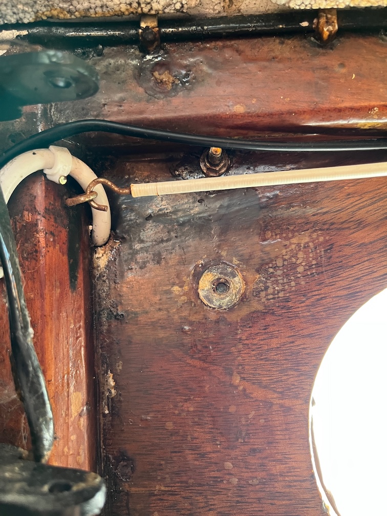
However, before I test out these options, I really need to do something about the fixings. The two bolts holding the base plate to the cabin side need to be removed. One is brass, well it was and is now copper, and the other is stainless. This is the same on both sides. Not sure why but they need to be taken out. The ex-brass one to be replaced and the stainless one removed to allow the base plate to be countersunk such that the head of the machine screw does not protrude.
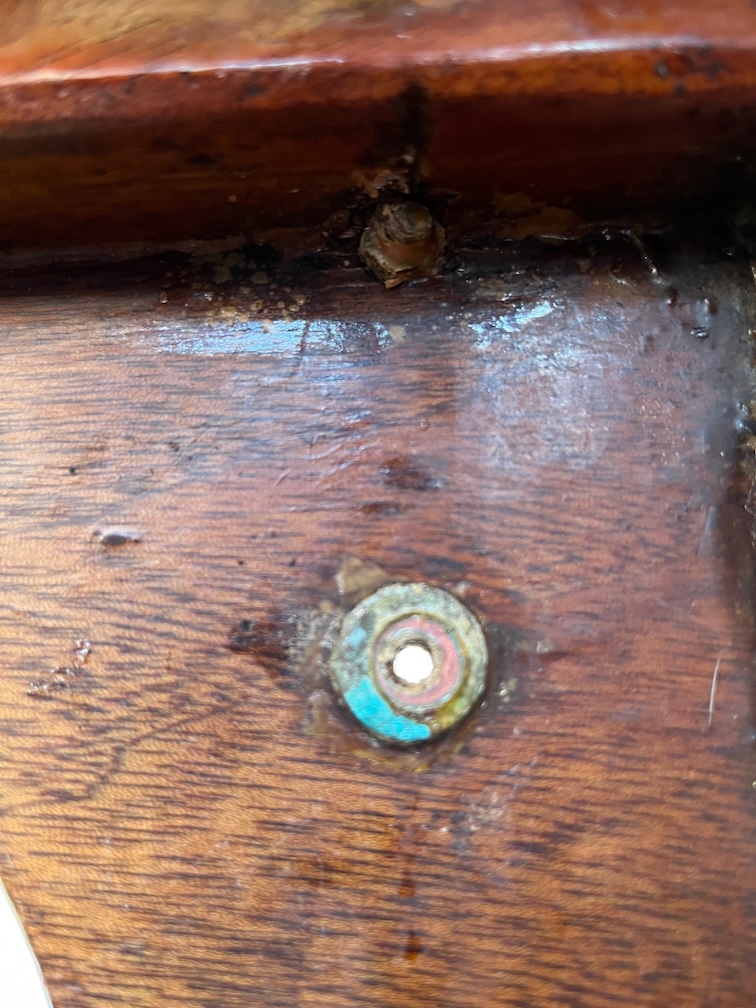
The head of the brass bolt was drilled with a shallow hole and then countersunk as can be seen here. A small diameter drill bit was used to drill a hole right along the length of the bolt and then opened up using successively larger diameter bits until the entire bolt was removed.
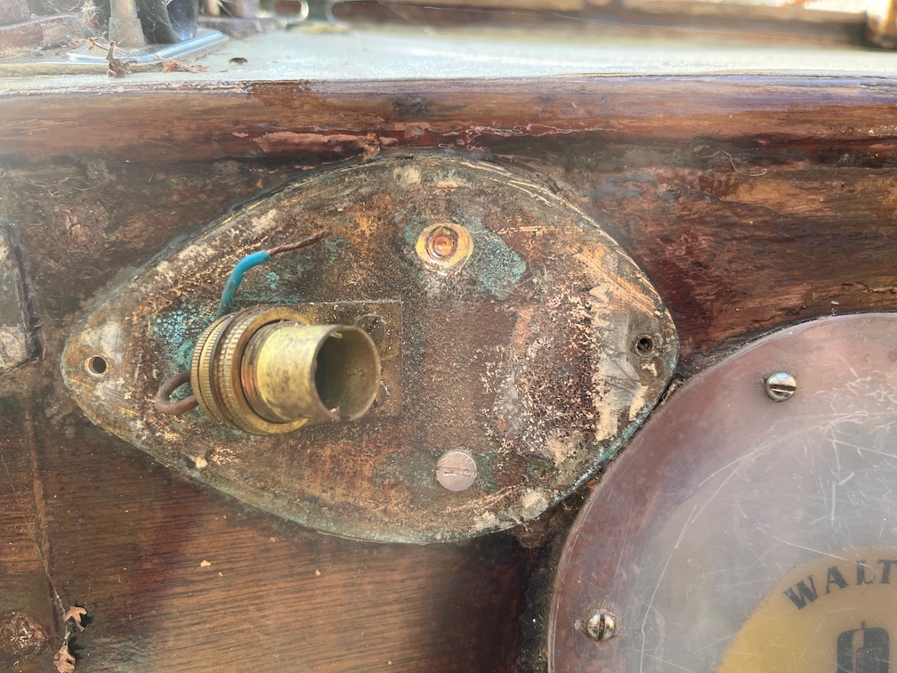
In this photo you can see that the lower, stainless steel bolt has been removed and the upper brass bolt remains.
It didn’t take long to remove the upper bolt, just a steady hand to prevent the drill bits from breaking.
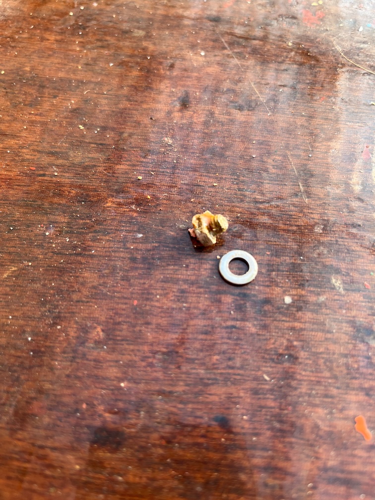
Here is the remains of the bolt, the nut and washer.
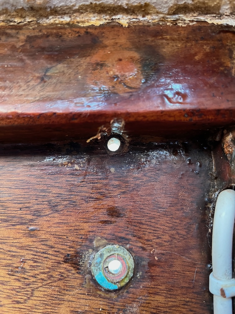
The nav light on the opposite side was done in the same fashion except on this side, the lower bolt was the brass one and the upper one stainless steel.
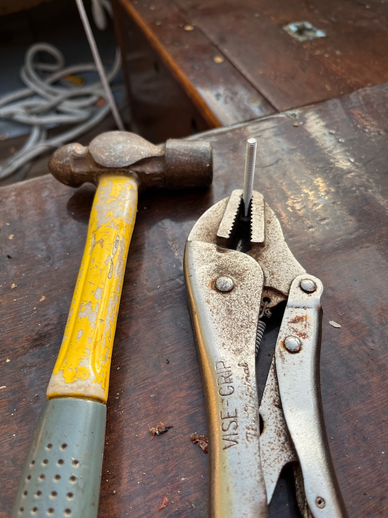
I used vice-grips on the inside to hold the nut whilst I unscrewed the bolt from outside for the stainless bolt, but the other one had to be knocked out. I did this on the first side as well but forgot to take photos.
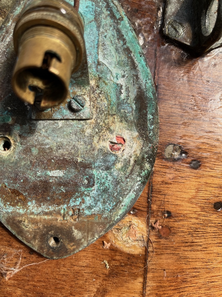
The brass bolt and nut had degraded into copper and at some time in the past it has been knocked off, as can be seen in the photo, just leaving a short length of the bolt in the wood of the cabin side.
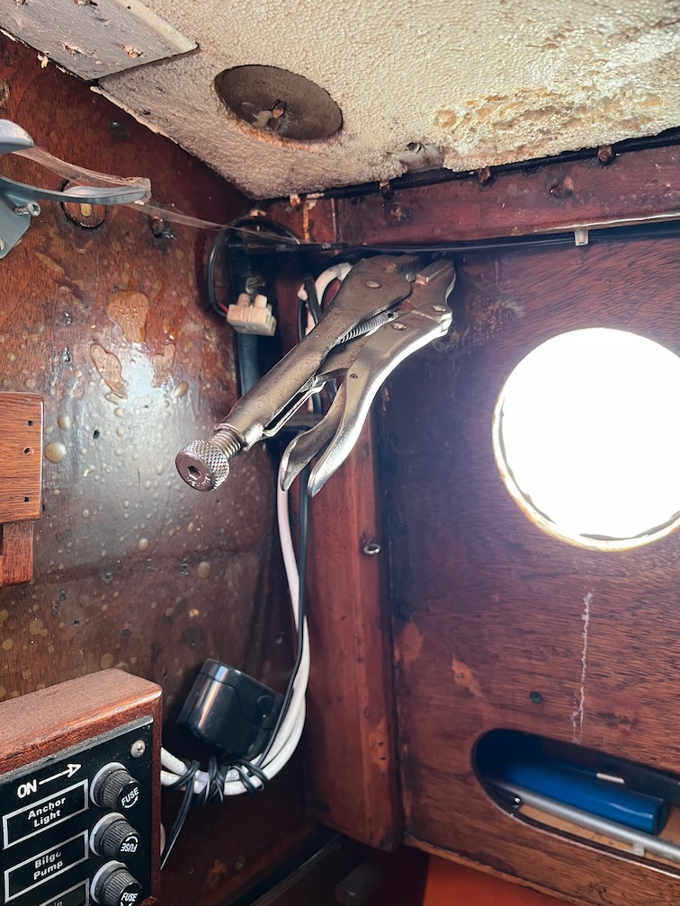
I used a bolt as a drift and gently hammered out the remaining bolt from the inside. The vice-grips are to stop me from hitting my hand which probably would have happened if I had held the bolt and tried to hit it.
In the end, the bolt stayed in the base plate which itself came loose from the cabin side. Still, the copper bolt was easily remove with a gentle tap on the reverse with the hammer.
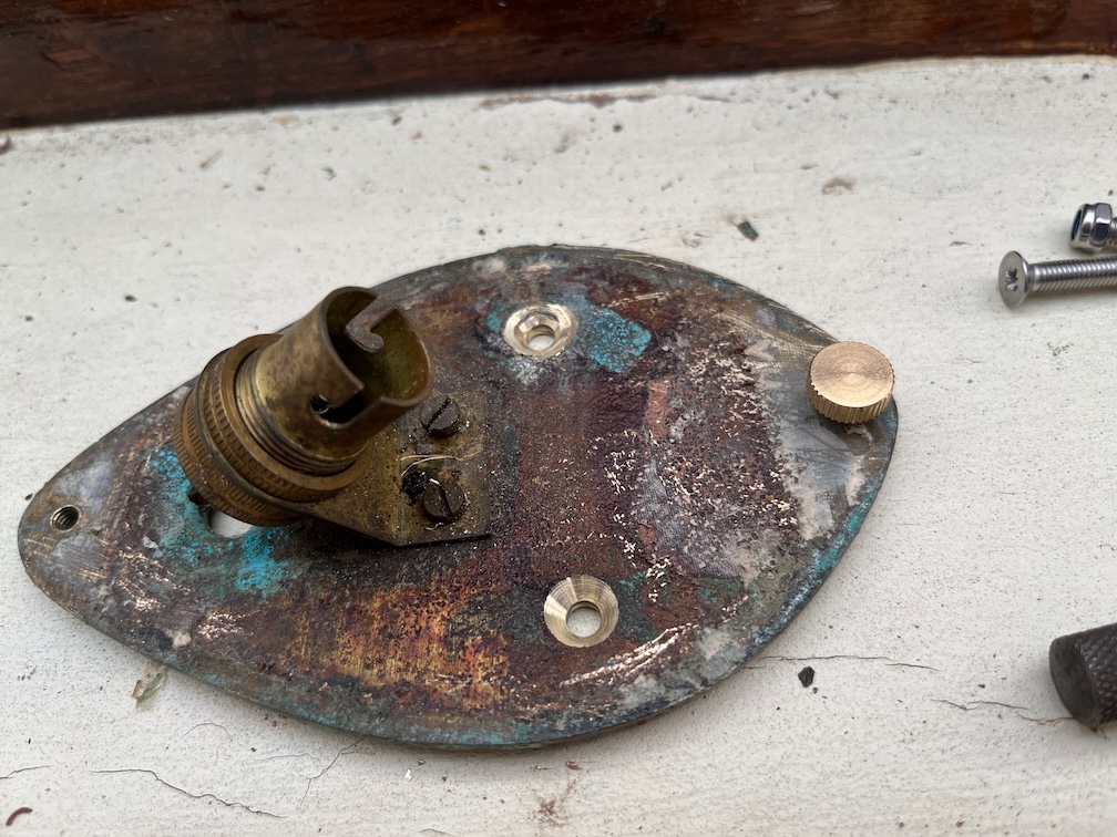
The two holes were then countersunk as you can see. I gently drilled the countersink, taking off a little at a time and offering up a machine screw of the correct size each time to check that I didn’t remove too much of the base plate. The other side was similarly countersunk, but you don’t need to see a photo of that as it’s more or less the same as this one.
So far, so good. I only had one machine screw of the correct size so the next thing to do was to order more. With that done I turned my attention to the outer casing fixings.
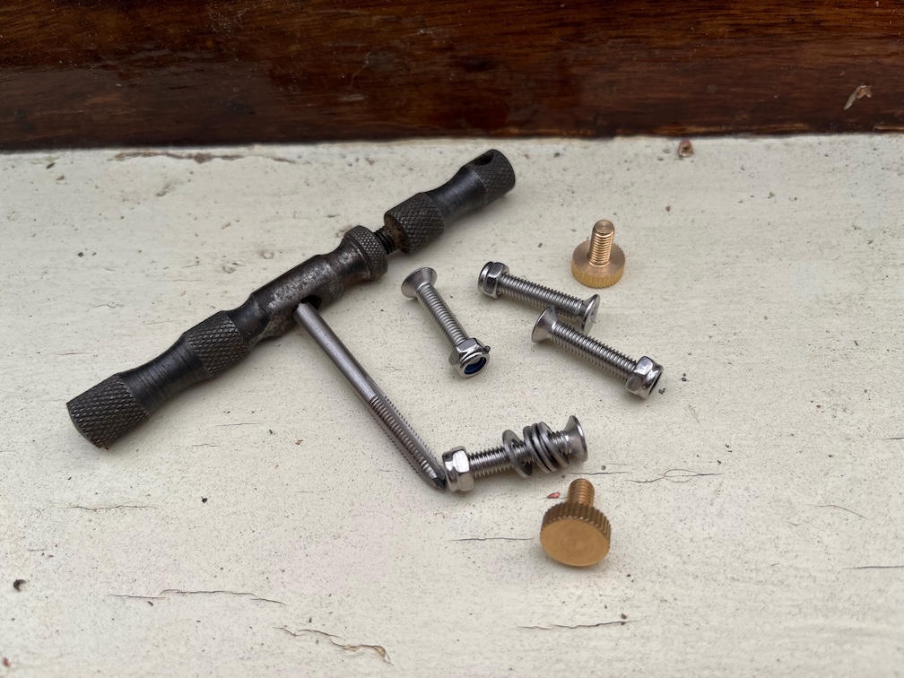
From the photo above you can see that one of the fixings is a knurled bolt, presumably original, whilst the other is a stainless steel wood screw that goes through both holes in the light and into the side of the cabin and this is the case for both nav lights. I presume that the lights had two of the knurled bolts each and that over time two had been lost and were replaced with the screws.
Time to fix that.
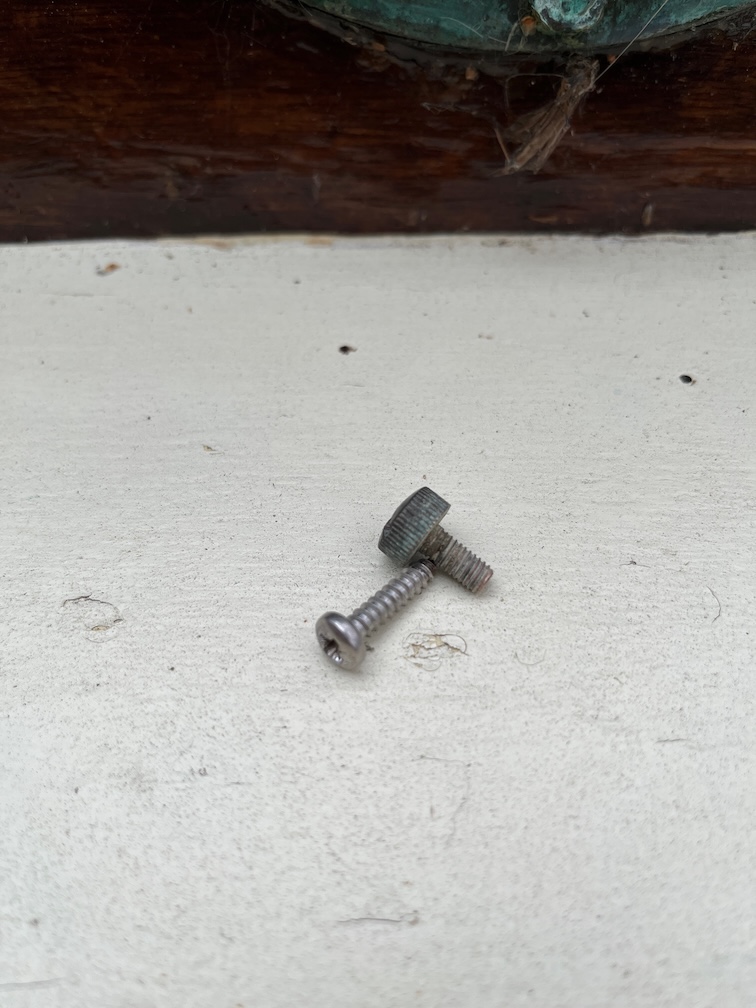
These are the fixings. The screw will be replaced but I could only find brass knurled bolts that will fit.
The problem is the recesses in the casing. The heads of the knurled bolts measures 11.2mm in diameter and although I can find stainless steel knurled bolts, only the brass ones have a head that will fit into the recess. Even then it might be tight as those have a head diameter of 12mm, so it’s going to be close. Also, I think that the nav lights are bronze, not brass and I’d really like to have bronze replacements. However, those would have to be custom made and that would be exceedingly expensive. This is also why I was looking at stainless ones.
Never mind, brass ones are on order and I’ll liberally coat them with some thing when I reassemble the lights to slow down the leaching of the zinc from the brass over time. The pack also contains 5 bolts so I’ll have replacements until I can find bronze or stainless replacements.
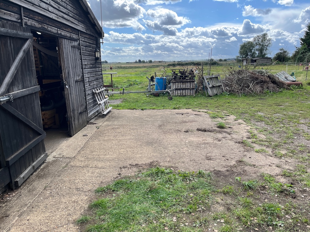
The time has come to move Shoal Waters from off the hardstanding in front of the workshop and into the Hay Barn.
Here’s the reason why. It’s not easy trying to work on the boat when she’s open to the elements. This was taken a few days ago and, to be honest, it doesn’t rain this hard very often, but I think you get the point.
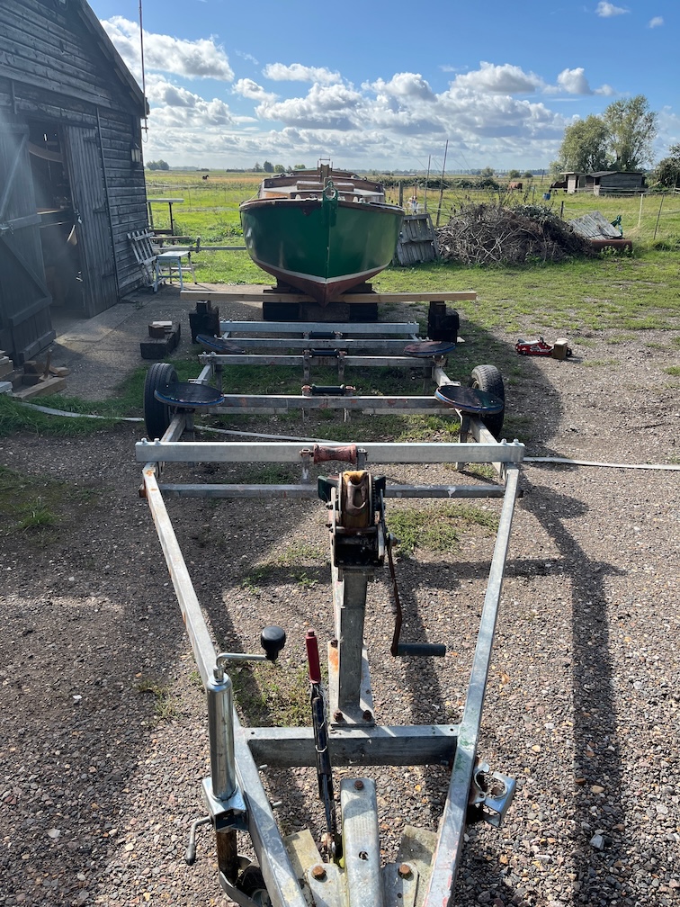
So, today’s boat task is to put Shoal Waters onto the working trailer and move her into the Hay Barn.
First things first, move the trailer close to the boat.
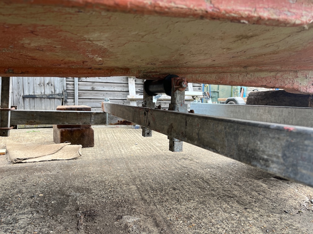
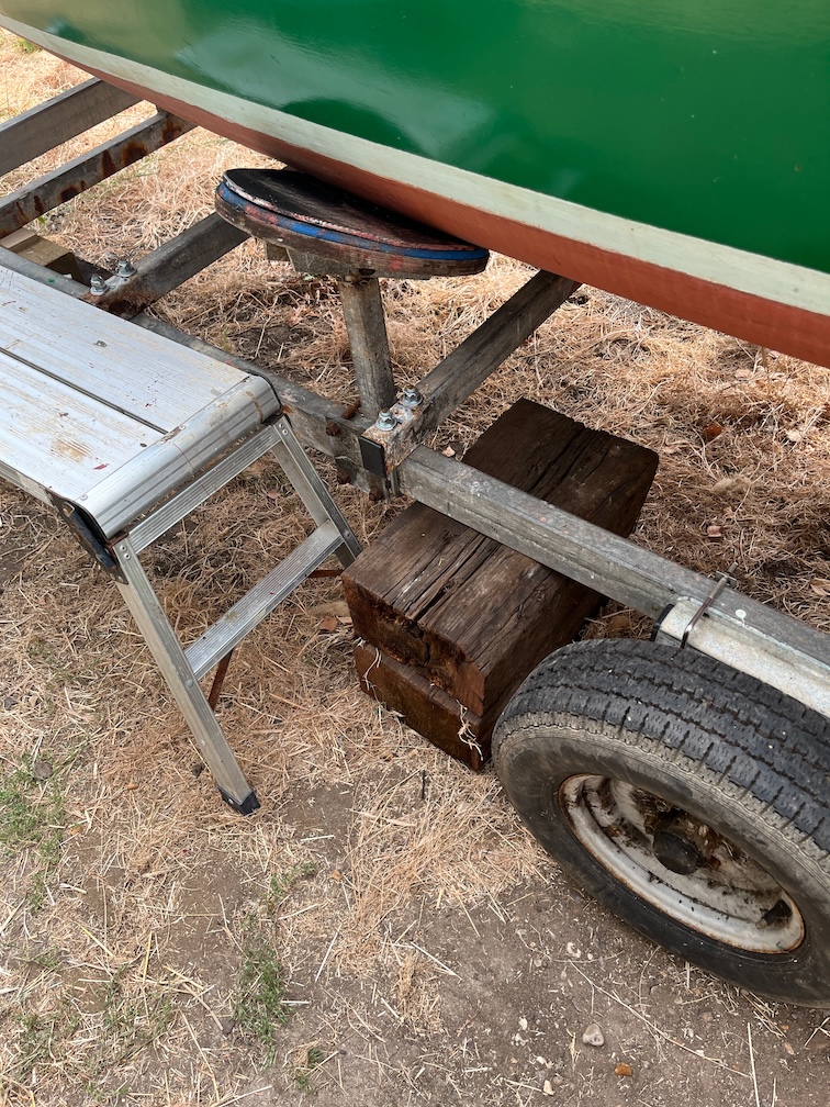
Then jack the boat up using a specially made beam to form the bridge at the front.
The beam bent a bit as you can see here, but not enough to worry about just yet. However, before the next lift I’ll reinforce the beam, probably with a length of 6mm steel bolted to one or both sides. For now it’s good enough as the wood is not old and therefore still quite strong.
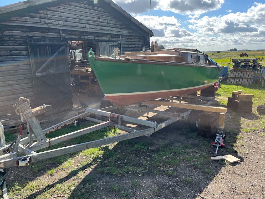
With the hull lifted up sufficiently, the trailer could be rolled underneath the boat. This wasn’t as tedious as getting her off the trailer a few weeks ago, but still tedious enough to make me want to find a better way to do this before the next lift is required.
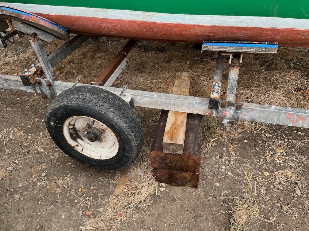
Finally the boat is on the trailer, the side supports are bolted in place, the centreline rollers adjusted and the beam removed.
Once one of the rollers touched the keel, the others were lifted to also touch and then bolted in position.
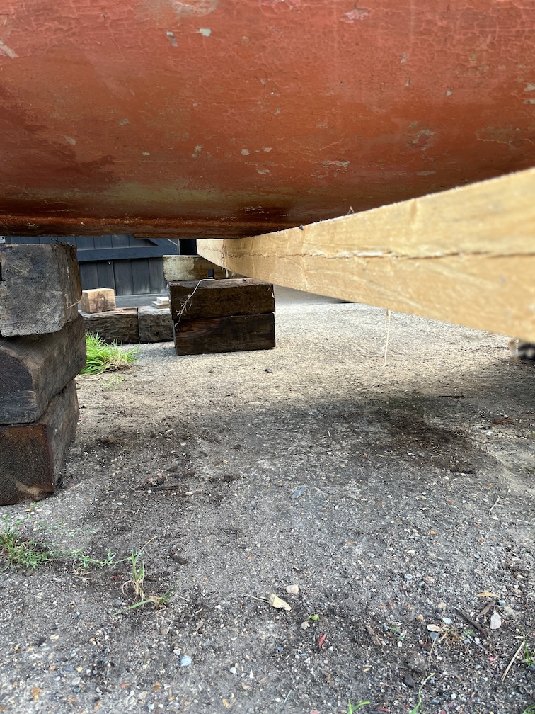
a thin piece of wood was put onto the front new cross beam but it wasn’t quite thick enough as you can see. Once Shoal Waters is in the barn I’ll fashion a better filler for both the new cross beams as these do not have rollers.
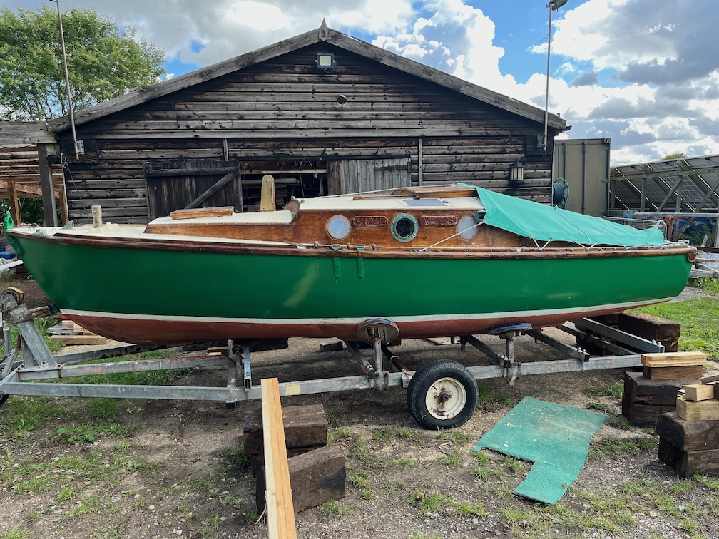
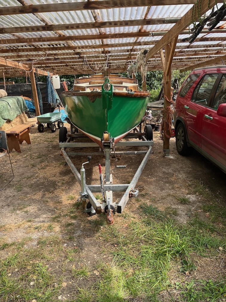
And finally into the barn. Here she is protected from the elements and the only thing that needs to be watched is your head when climbing in and out of the boat.
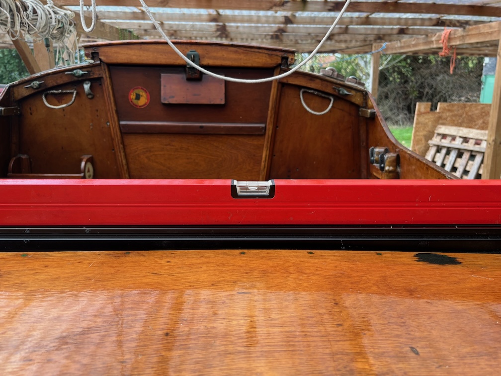
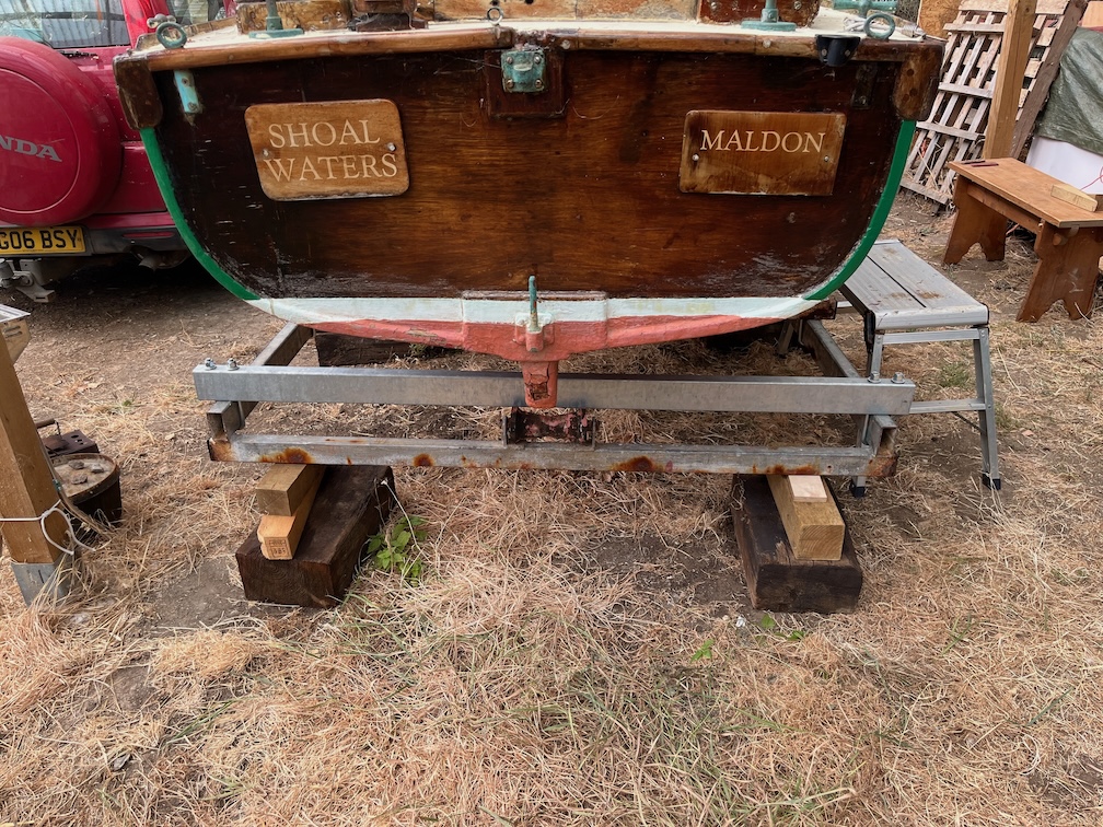
As usual I used a spirit level across the aft end of the cockpit to level the boat.
The trailer being blocked up just behind the wheels on both sides.
The port side blocking is about 75mm or 3″ taller than the other side due to the slope of the ground underneath.
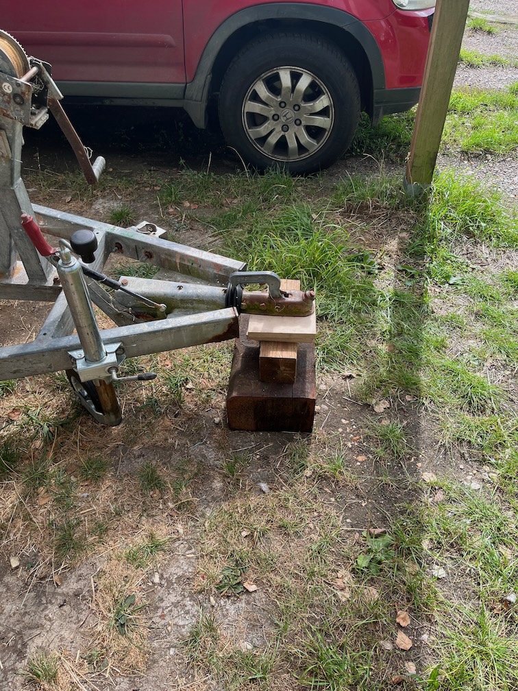
Blocks were also added under the towing hitch…
…and under the back end of the trailer. This makes the whole thing very stable and the boat does not rock or threaten to tip over when you climb in and out.
The hardstanding is now clear of the boat…
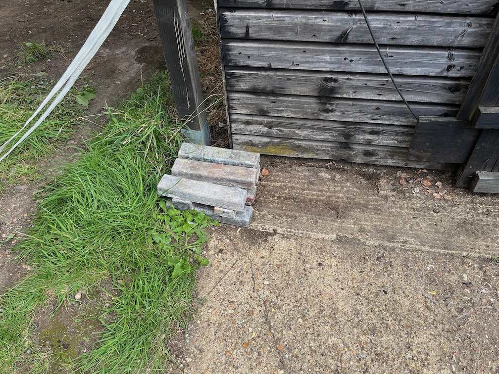
I even put away all the wooden pieces that were used to block up the boat and trailer at various times. What is left is the lead ballast. I need to decide what to do with this. When it was originally cast by Charles Stock he had to melt the lead is stages, pouring each pot into the mould before melting the next.
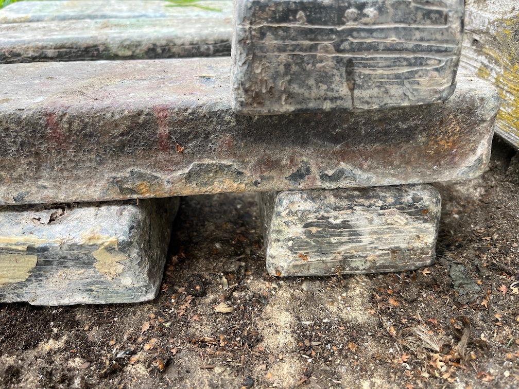
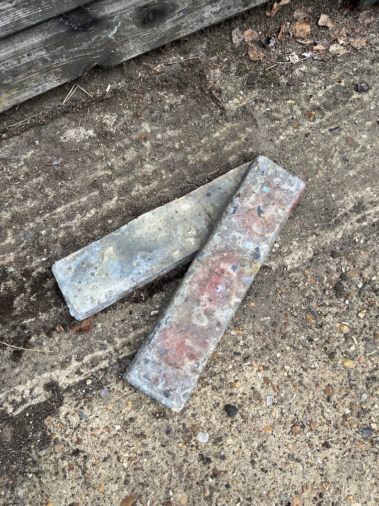
This, unfortunately, meant that the layers only partially bonded together, you can see the layers in the ends of the pieces…
…and one has come apart. I should probably melt these down one at a time and recast them to the same size but in one go to get rid of the delaminating problem.
Still, that’s for another day. for now, Shoal Waters is under the barn roof and I can continue working on her without having to worry about the weather.
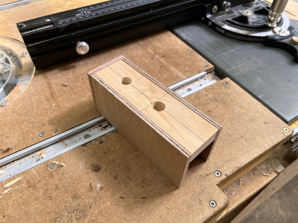
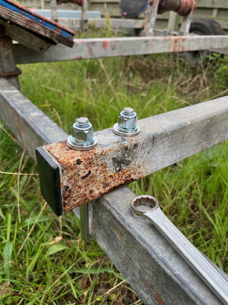
Today’s task, or at least the Shoal Waters related task since I have other tasks that I wish to carry out today as well, such as building a rope maker, is to drill the holes into the ends of the two new cross beams and then cut down and fit the u-bolts.
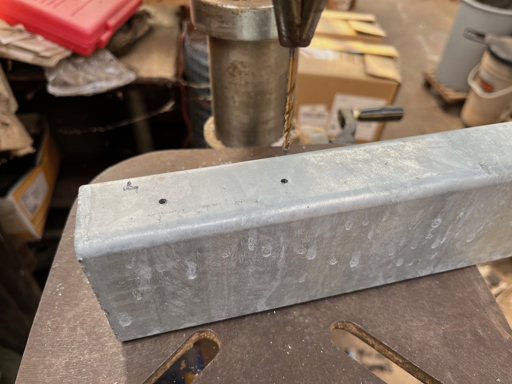
This is the jig I used to locate the holes in the correct position. It fits over the end of the beam and guided the drill bit until a small indentation has been cut into the metal. The jig is removed and a small diameter bit is used to drill right through the top wall of the beam. This was repeated for all four beam ends. After that the correct sized hole was drilled using the indentation to center the bit.
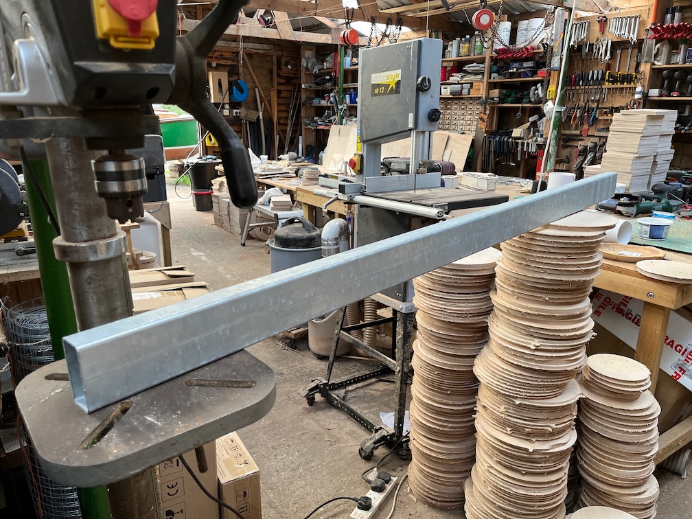
The next part of the process is to take a cross beam into the workshop and put it onto the drill press, supporting the other end to keep the beam perpendicular to the drill bit.
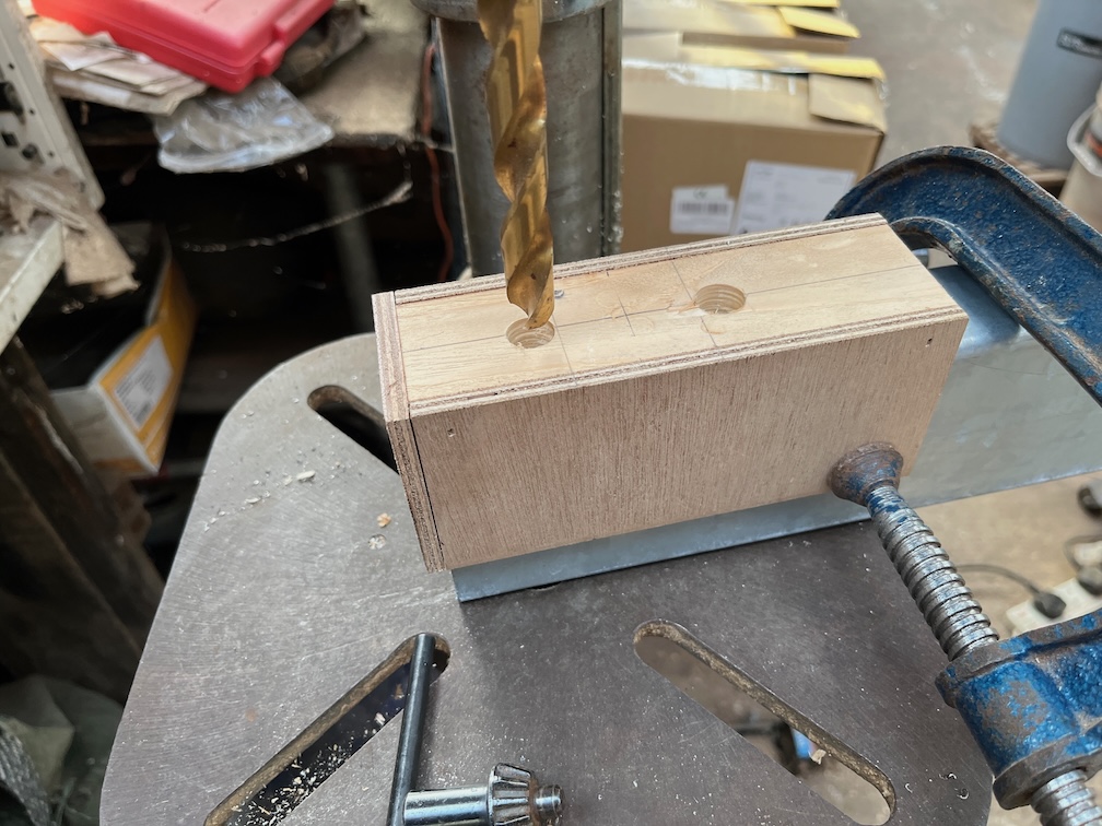
The jig is clamped to the end of the beam and the correct sized drill bit used to make an indentation in the beam. This is done on both ends and on both sides of the beam.
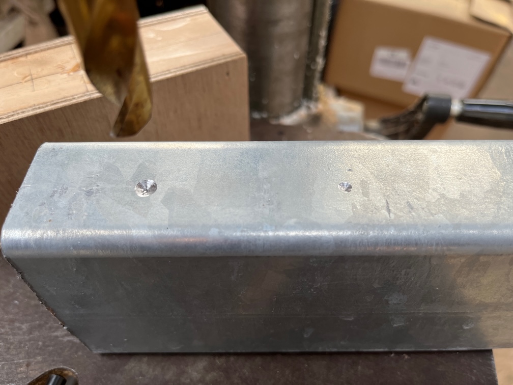
Here is the result of one end. The size of the indentation isn’t critical, it’s just there for the next stage.
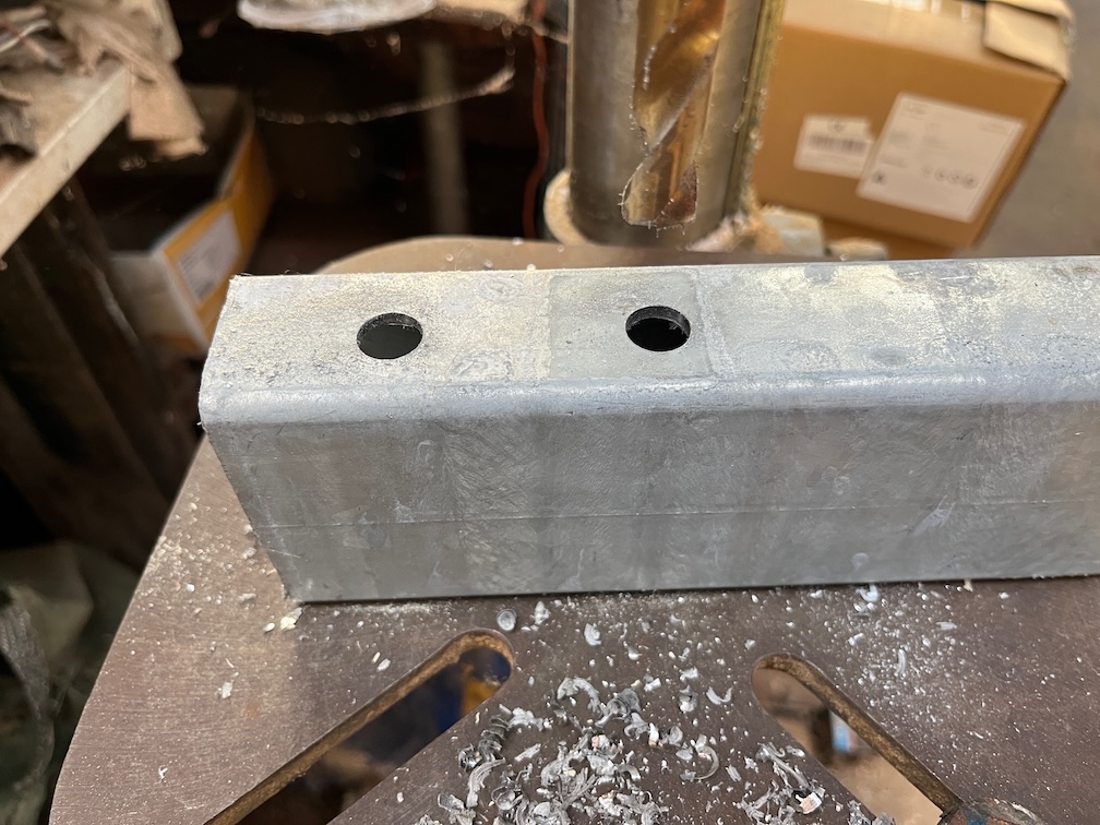
A small hole is drilled through the wall of the beam, in this case a 3mm hole as this is the smallest bit the drill press will hold. Again this is done on both ends and both sides.
The large drill bit is then used to open up the hole to the correct size.
This results in a perfect fit for the u-bolt, which was the intention. This shows how a simple jig turns a complicated job into something a lot easier to achieve.
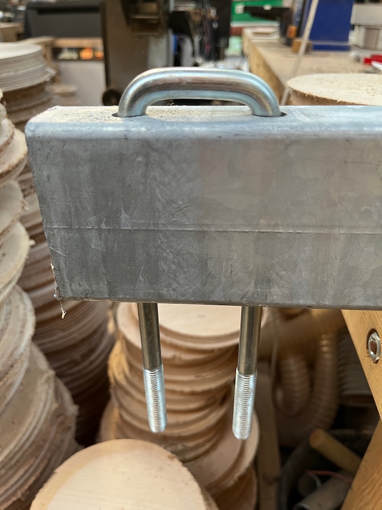
Finally, the u-bolt legs are cut to size and the beam is bolted securely onto to the trailer.
I only had time to do one of the beams this evening, I also spent some time using the CNC Route on another task which I also didn’t finish. Both of these tasks will be completed tomorrow.
Just a quick update to the work on the working trailer. The M12 penny washers arrived late on Monday afternoon so I wasn’t able to get the work done then but had to wait until this afternoon instead.
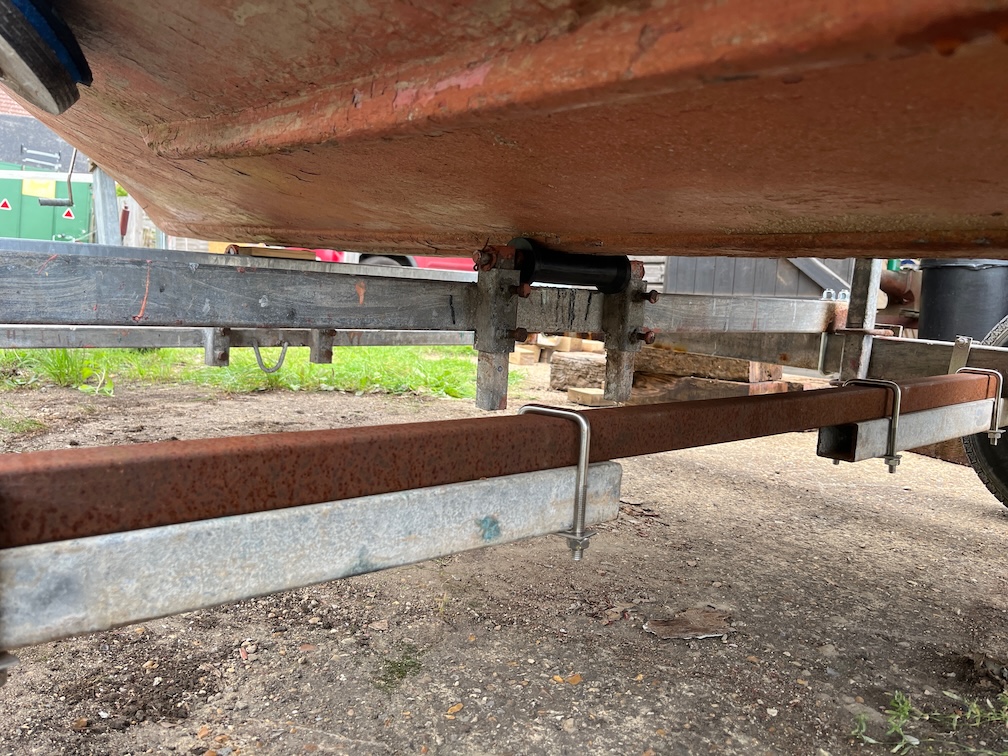
The task for today was quite simple. Cut 35mm off each of the legs of the six u-bolts and use the shortened bolts to fix the cross-beams to the trailer in the place that I need them to be, which is on top of the side-beams.
This is the first of the six done and you can see the two M12 penny washers underneath the standard M12 washer upon which the bolts sits, ensuring that there is enough thread to give a strong joint.
It didn’t take long to do all six u-bolts, about an hour all told and here are the cross beams now done. I will paint the cut ends of the bolts with something to prevent them from rusting, but that will have to wait for a dry day.
The taxt task on the trailer is to fit the two new cross-beams and for this I need to drill two 13mm holes in each end of the beams and these need to be perpendicular to the beam and as a result parallel to each other. Not only that but they must straddle the side-beams exactly both ends otherwise the u-bolts will not fit.
This will be a case of measure about a dozen time to absolutely ensure that the holes will be drilled in the correct place before actually drilling the holes. This suggests a jig that slides over the end of the beam so that the holes, drilled through the holes in the jig, are in the same place from the ends of the beams which are almost exactly the same length. By almost exactly I mean less than 1mm difference, which is close enough.
There’s not been much work done on Shoal Waters for the last seven weeks, I had minor surgery on both feet which has meant I’ve been unable to walk properly due to the dressings and the discomfort, if not outright pain.
Now that my dressings have changed to less obtrusive ones and I can walk, sort of, I can get on with things that do not require me to wear shoes, that’s agony, nor kneeling down as putting my feet in that position is also just a tad painful.
However, the work needs to get started as the evenings are getting darker and I still have a great deal of work to do.
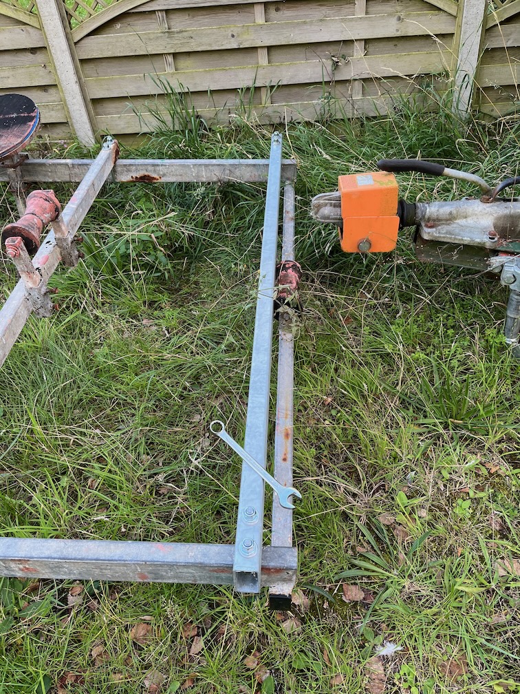
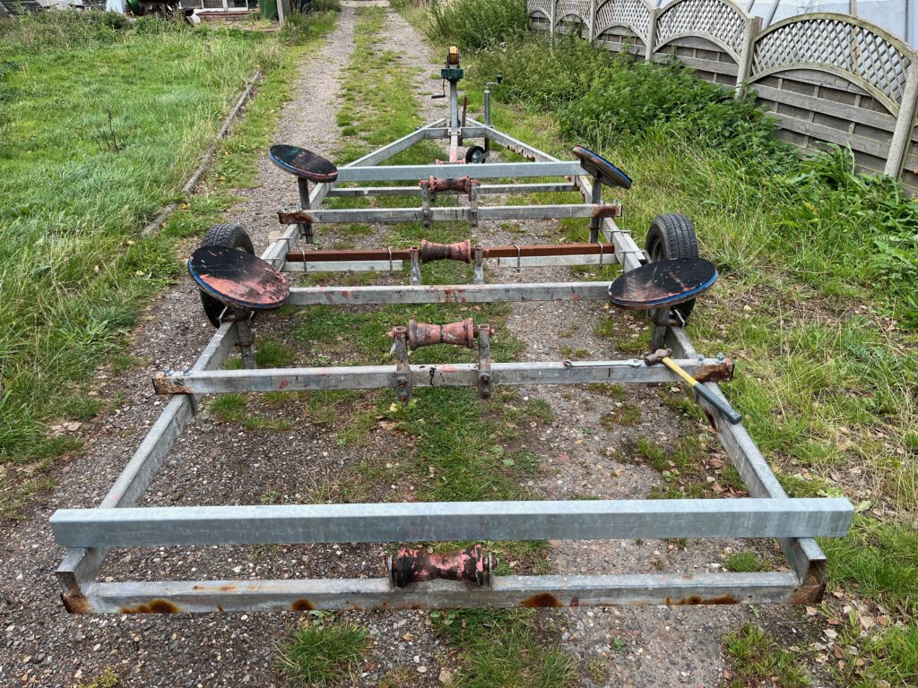
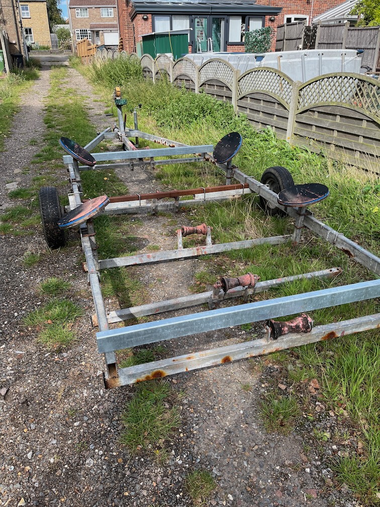
Today’s task is to start work on the trailer.
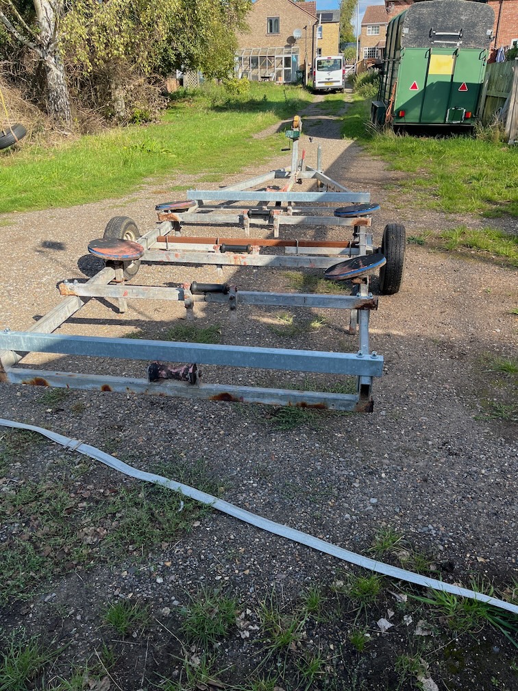
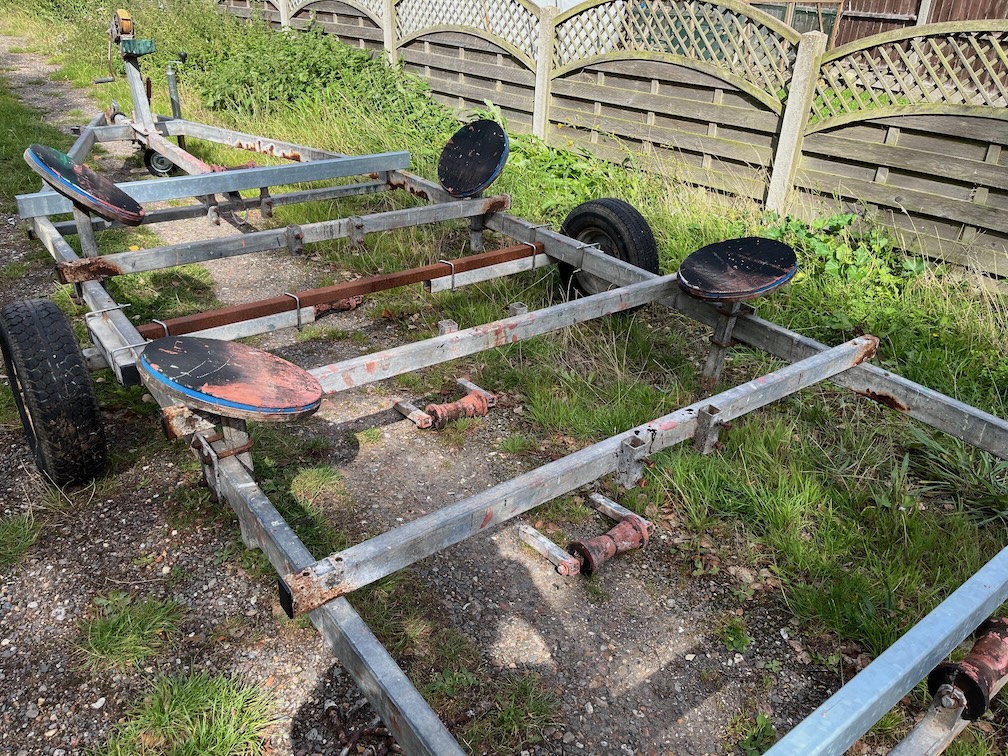
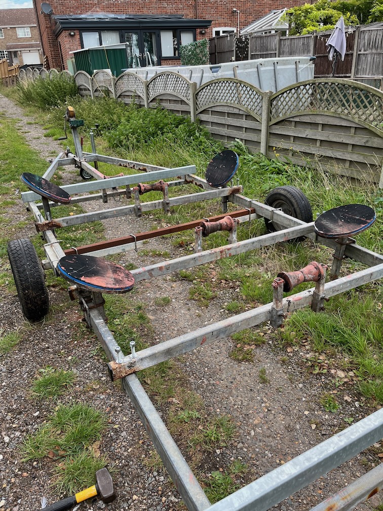
In order to work on the railer I needed to move it out of the weeds that have grown around it and onto the drive so that both sides are accessible.
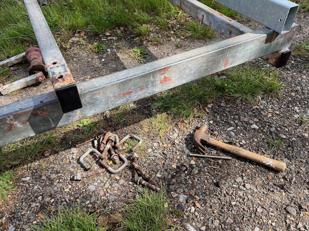
Each of the u-bolts holding the three under-slung cross-beams were cut using an angle grinder. I could possibly have removed a few of the nuts but to be honest, that would have been a lot of work for a only a little gain, so I bought a pack of 20 metal cutting disks for the angle grinder from Amazon yesterday and once they had arrived today I was able to get going.
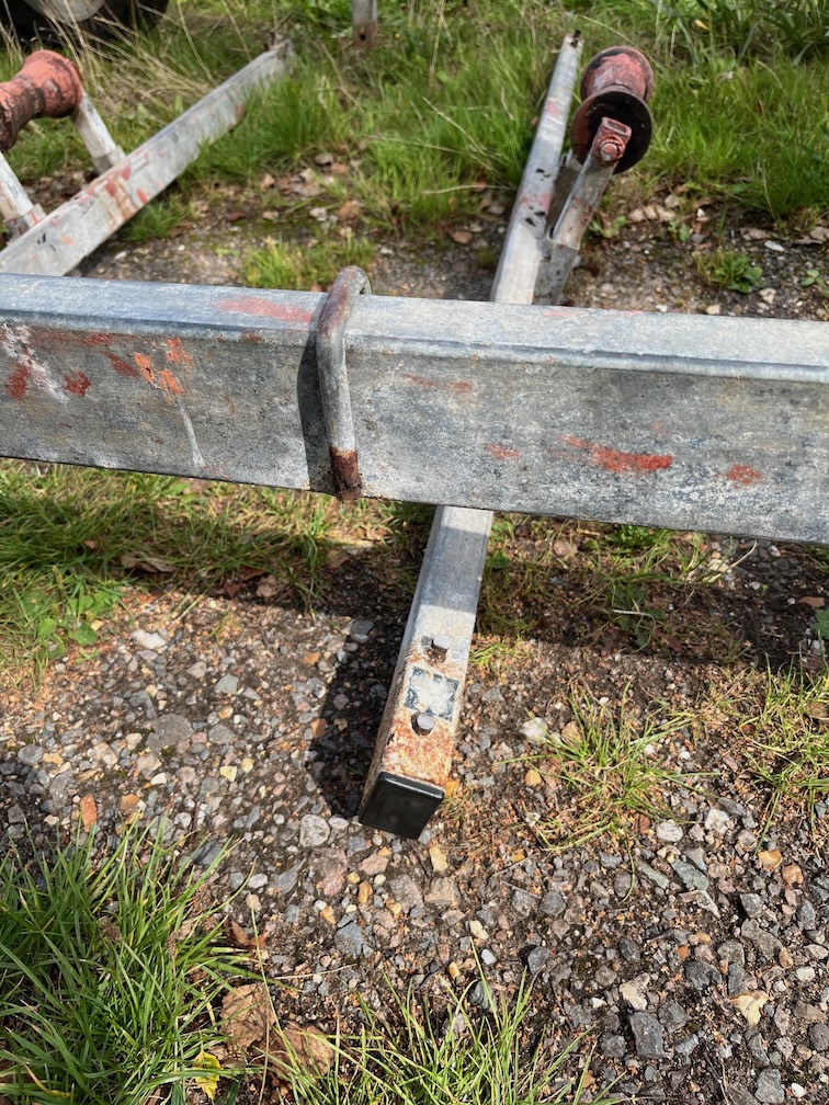
Then each of the legs of the bolts were drifted out with a hammer and drift. One or two of the legs had to be hammered really hard to get the to move due to the rust, but they all came out eventually.
With all the rusted u-bolts removed, the cross-beams were put on top of the side beams. The rollers were taken out at this point as they tipped the beam over if left in place.
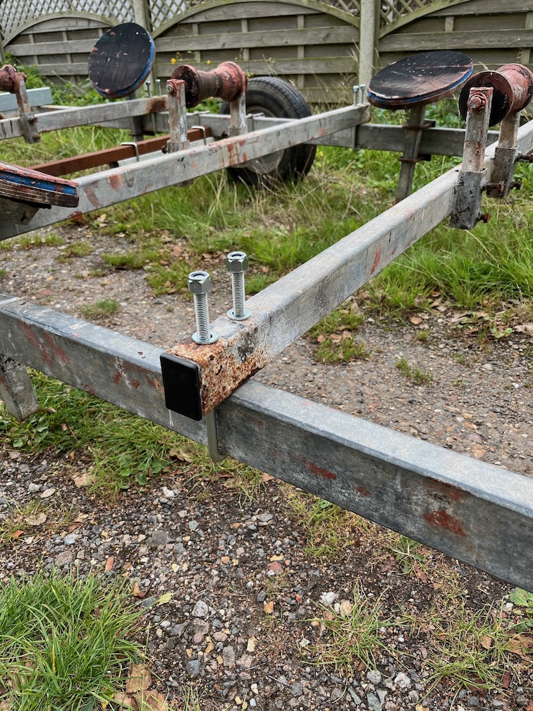
New u-bolts were then put into place as shown here. I was unable to get shorter ones that still fitted so these longer ones will be cut down once all is ready to be reassembled.
I didn’t tighten up the nus, they were just put on to stop the u-bolts from falling out.
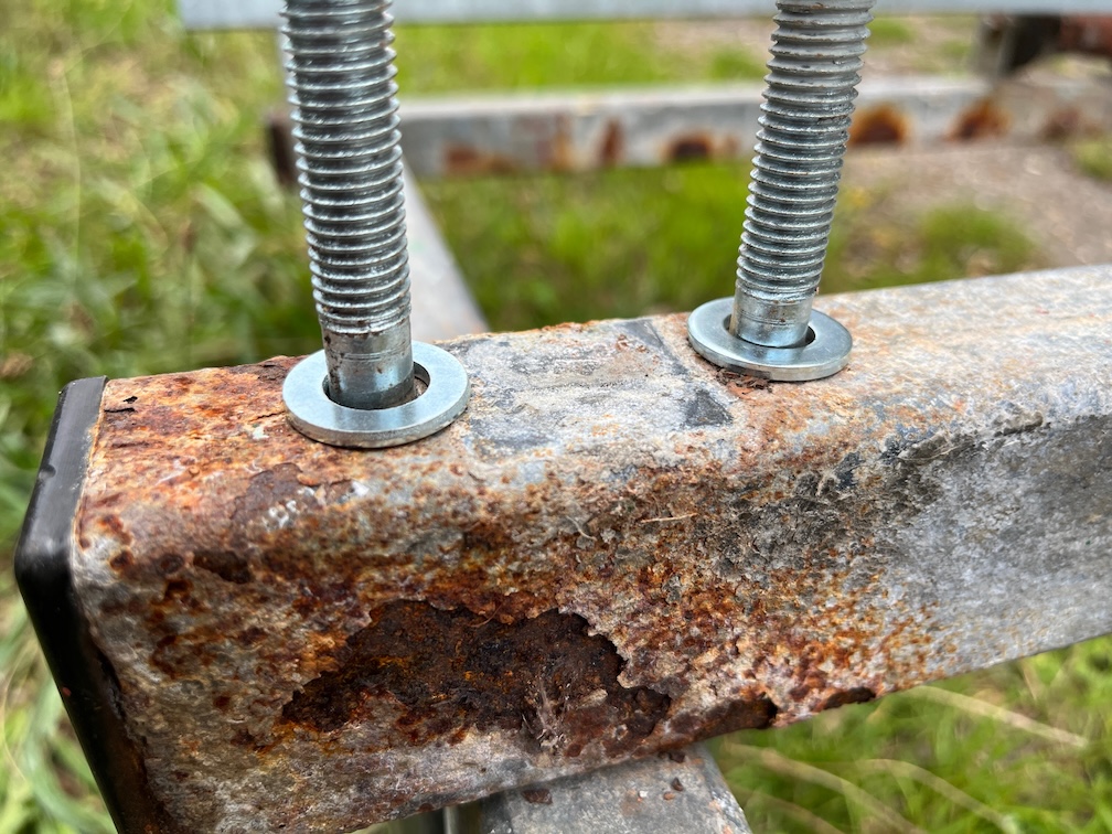
The threading on the legs of the u-bolts is onlu just enough to allow the nuts to be tightened up, but I noticed that on one u-bolt the thread seemed to be short as you can see here.
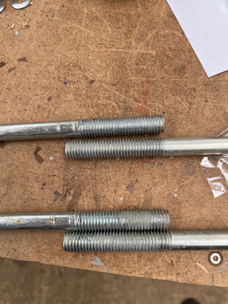
Comparing it to one of the other u-bolts I have in the workshop, the thread on this u-bolt is certainly too short for these cross-beams. I’ll use that on one of the two new cross-beams which are taller than the three old ones, and use one of the other u-bolts with a longer thread.
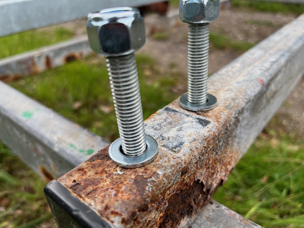
As you can see, the thread now extends to below the washer.
However, the thread still isn’t really long enough and will stop the nuts from being tightened down completely, so I have ordered some M12 penny washers, which are 2mm thick and 30mm in diameter, to put under the smaller washer seen here. Two per leg will easily allow the nuts to be fully tightened down.
That’s all I’m going to do today as even walking around causes my feet to hurt and I’ve had enough. The next task will be to cut the legs down to the correct size once the washers arrive, drill two holes in each end of the new cross-beams and fit those in place. At that point it will be possible to but Shoal Waters back on the trailer and wheel her into the Hay Barn.
Mind you, I’ll have to clear out a space for her first as Naiad’s trailer is in there covered in various bits and bobs.
Having two trailers is a little bit of a problem in two ways. Firstly there is the nomenclature. Since both will be used for both boats at different times, calling them Naiad’s Trailer and Shoal Waters’ Trailer is technically not correct, so I’ve decided to call this one the working trailer and the other the travelling trailer. This one will only be used for working on the boats and the other will now only be used to transport the boats. Seems like a good idea.
Secondly, what to do with the trailer that isn’t in the Hay Barn? We don’t have any other space for it under cover and leaving it out all year. in all weathers round will cause it to rot away. So, I’ll also have to build a small shelter of some description for the trailer that isn’t in the hay barn. Two steps forward, one step back.