I gave myself an easy day yesterday as I find that working over the weekend without a break seems to make me more tired during the week. That isn’t to say that I did nothing on the Shoal Waters project, just no physical work.
But, I resolved to get the part of the template task that is bugging me fixed.
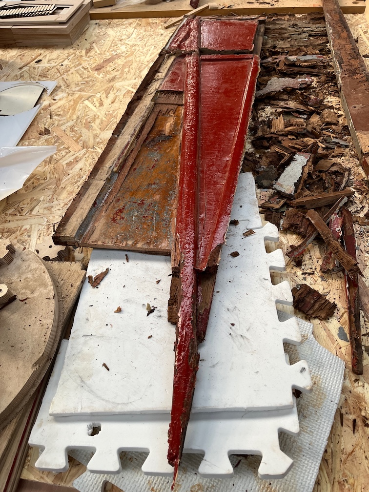
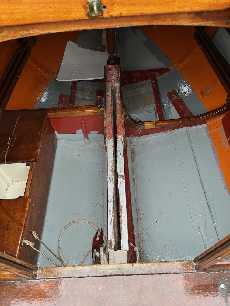
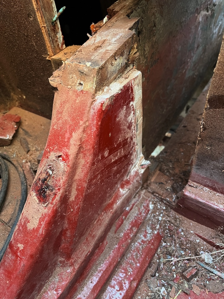
It’s this part. The bit at the bottom corner of the template really should be pointed, but it’s that shape now as I’ve not been able to get the last pieces of the original plywood out. It’s in an awkward position and one in which the rest of the boat restricts how far I can use a chisel. The only direction that I can get a blade in further than I have now is from the front of the pointed end but kneeling on the cockpit trying to work under the bridge deck.
In the end I just gritted my teeth and just scraped away at the last bit of glue and plywood until I got it all out. Took about an hour and frankly, this was the hardest part of the work I’ve done so far. Of course, keeping my right leg far enough away from the business end of the sharp chisel doesn’t make it any easier, but I have no wish to stab myself in the thigh with a sharp pointy thing.
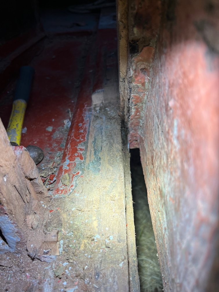
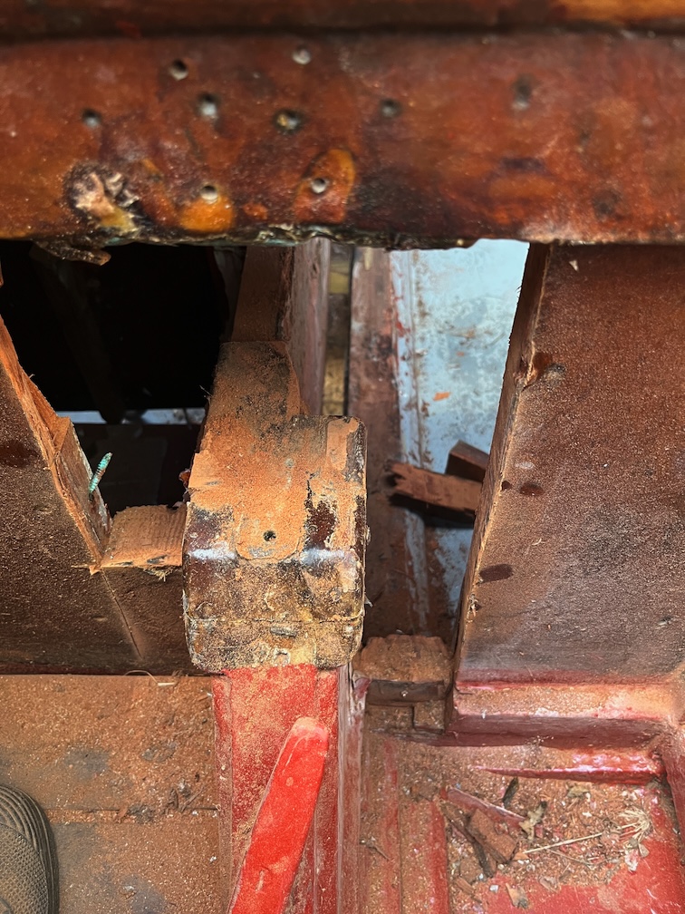
And here’s the result. You can see the lip at the bottom of the slot and the aft block and the 1/4″ groove in the keel and the block.
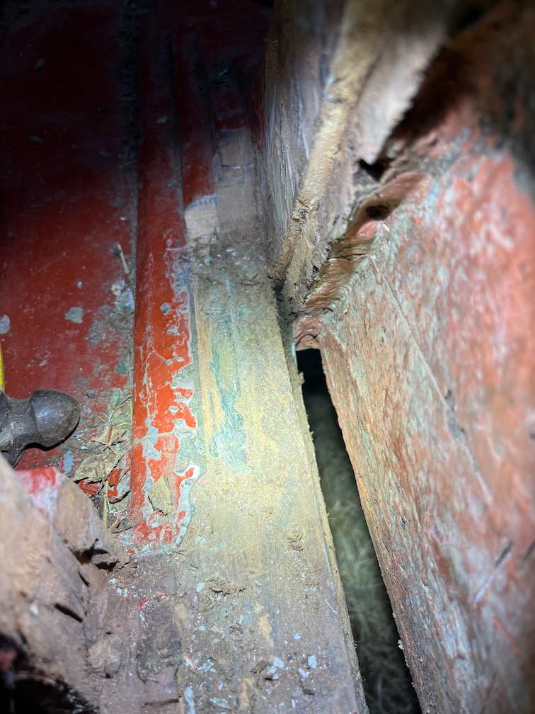
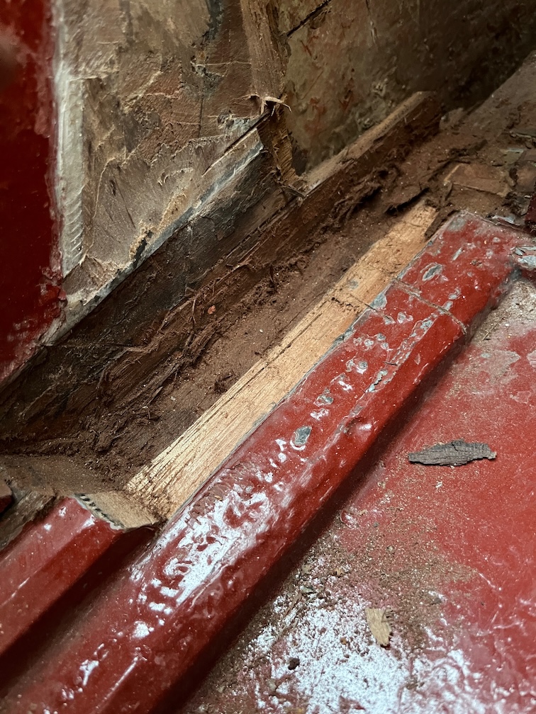
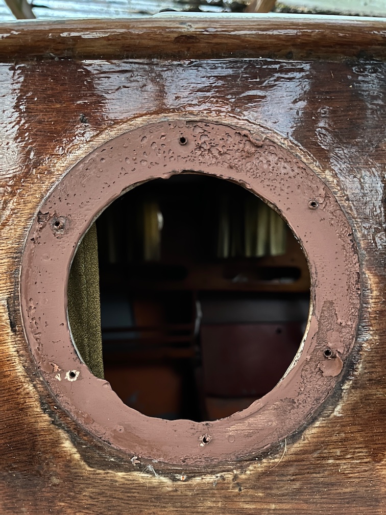
Here is is from a slightly different angle.
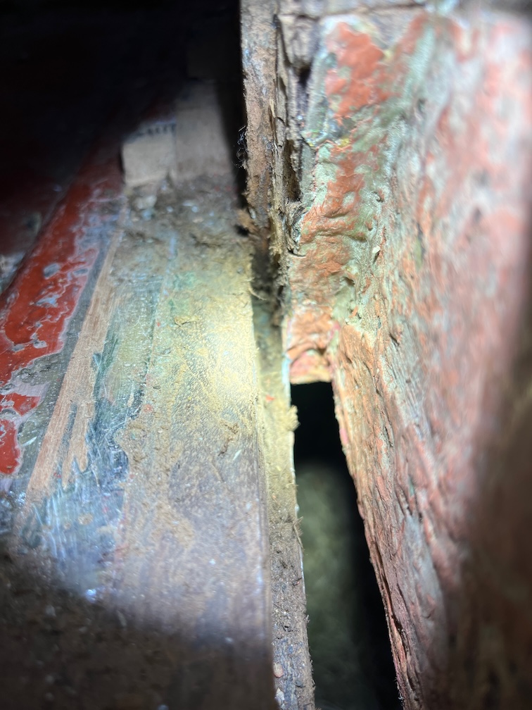
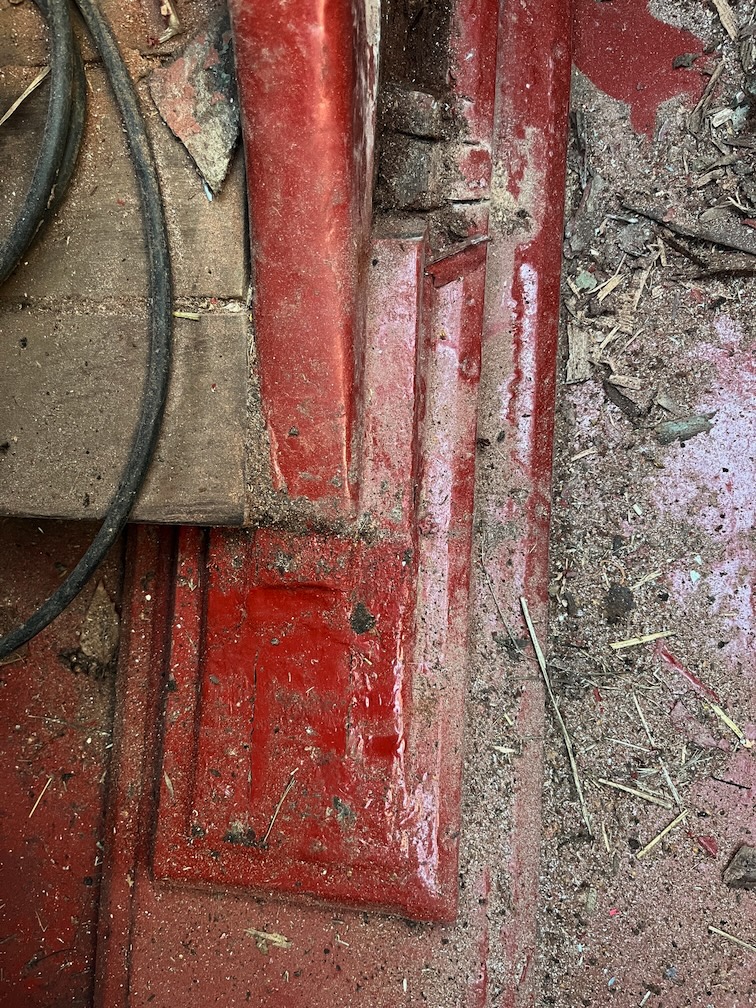
And finally a close up of the pointed bit, albeit a little out of focus.
I’ll still need to tidy that up a bit with sandpaper but now that the old plywood has been removed that will not be quite so difficult. I’ll wrap a strip of sandpaper around a 6mm piece of plywood and run it into the slot a few times. It doesn’t have to be perfect as it’s going to be slathered in a marine adhesive, but it needs to be better than it is now.
Oddly, the other side should be a little easier since the other side of the case will have been removed by then, so the access will be a little easier. that and the fact that I know where the end of the pointy bit is, so I won’t be guessing how far in the slot reaches.
The last last if the tea break was to measure the pivot bolt as that needs to be replaced. This measured at 3/8″ in diameter and 4″ in length.
The next part of the repairs requires me to construct a template for the sides of the centreplate case case, which sounds easy enough but is a little more complex that you would think.
There are two templates to be made, one for the inner layer and another for the outer. Because the keel timber is curved, the templates must first be made from cardboard and checked before being used to create plywood templates from cheap 6mm plywood. These are then used to check the fit and to make any adjustment required. Once those are correct they may be used to cut out the marine plywood sides.
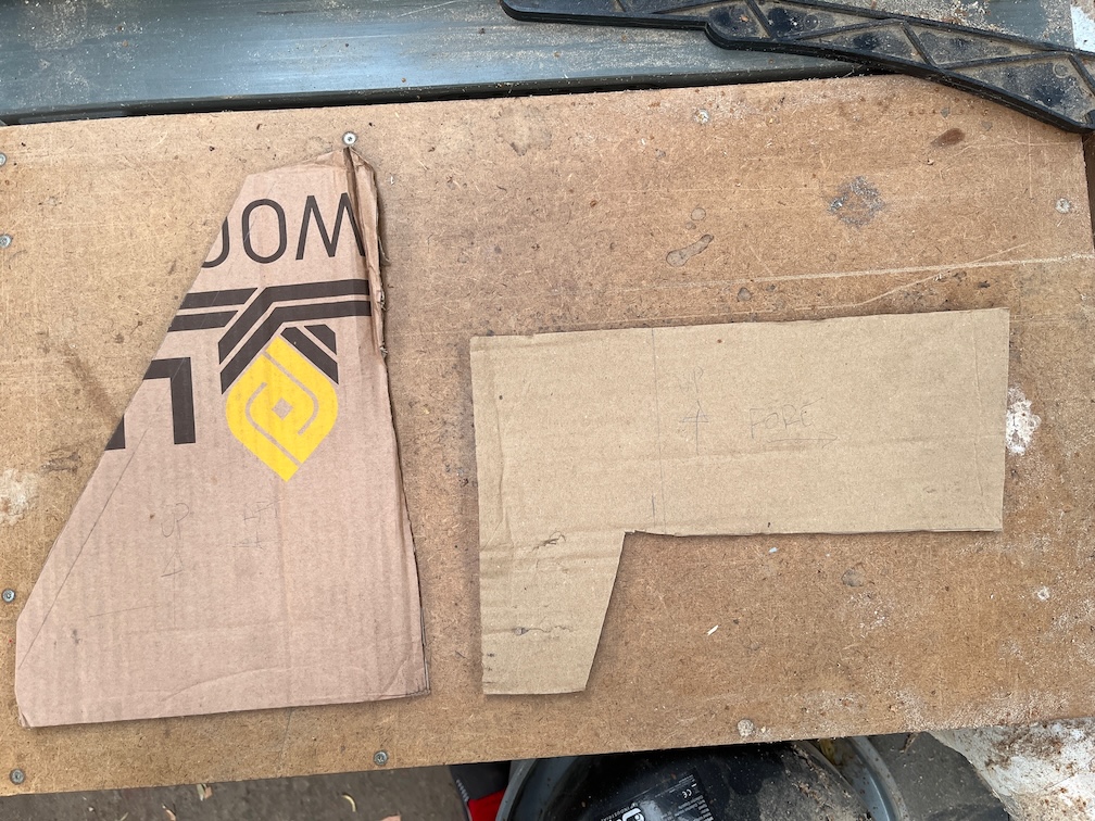
So, to start with, the template for the inner layer as the one for the outer layer cannot be done until the cheap plywood template is completed for the inner. Now, there are two tricky bits for the inner template, the ends since they recess into the fore and aft blocks.
I won’t bore you with the details for making these, suffice it to say that since it was nearly impossible to measure the required shape, I have to use trial and error until I had two pieces that gave me the correct shape for the ends. Lots of trial and error, I suppose it took around eight attempts to get a good fit.
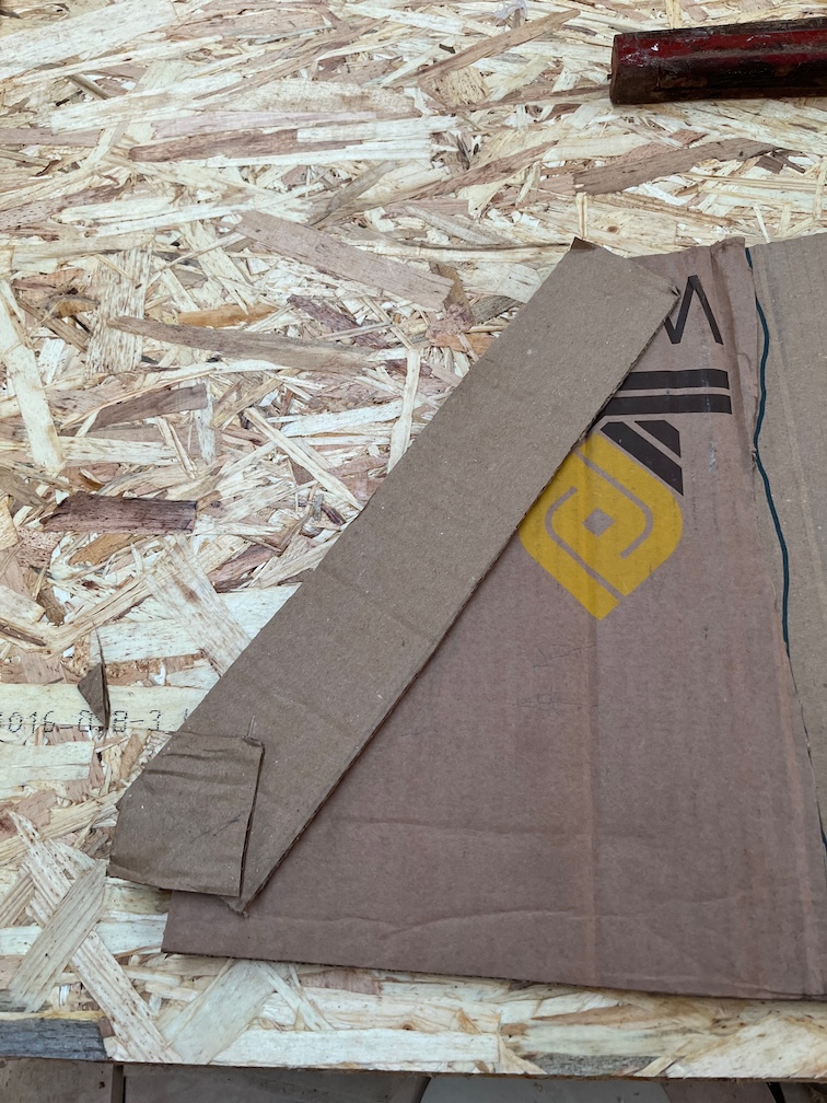
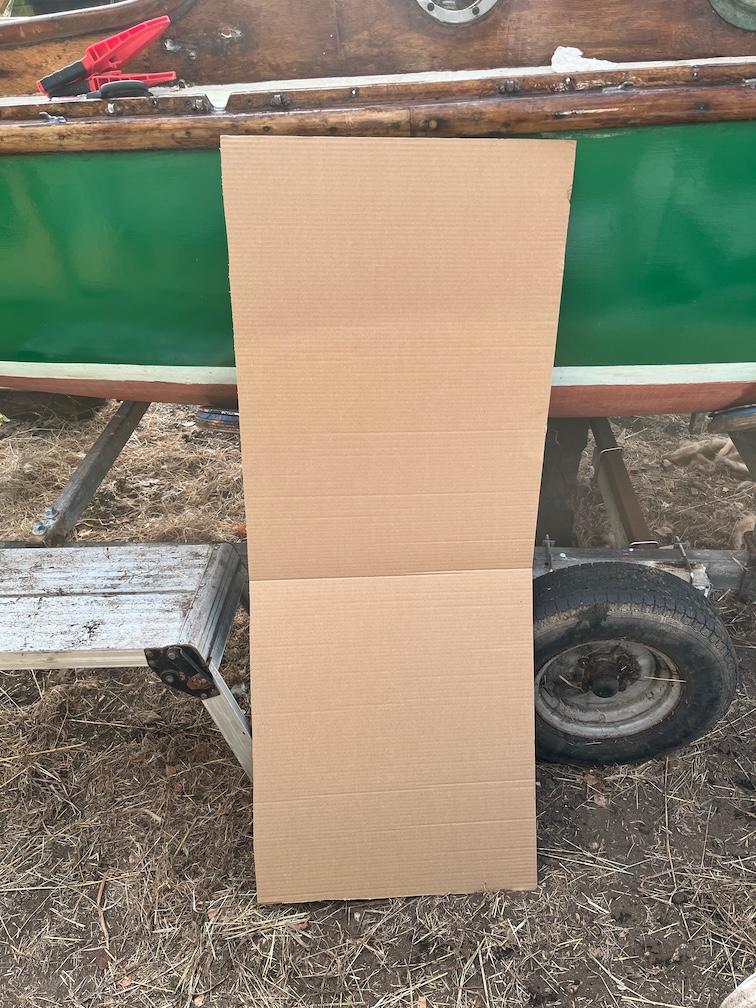
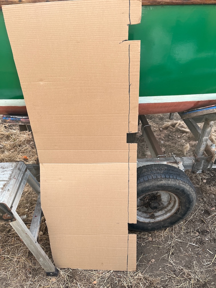
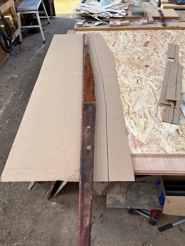
When the marine plywood arrived from Robbins Timber, it was covered with two pieces of cardboard, each the size of a full sheet of ply. I kept these for making templates. A piece that was too large was cut out, seen above.
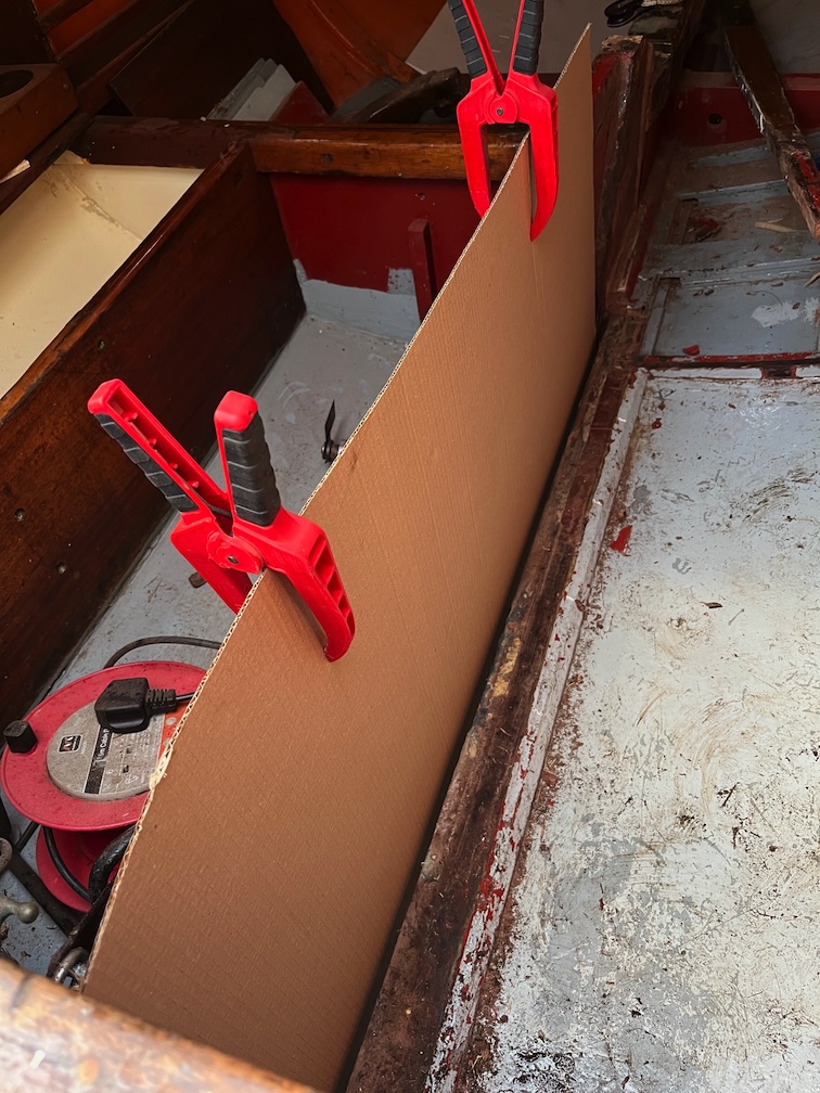
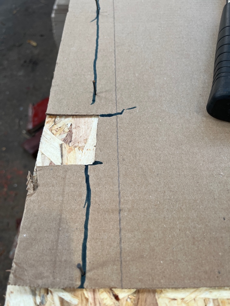
This had recesses cut out to fit over the supports on the outside of the keel and then clamped into place.
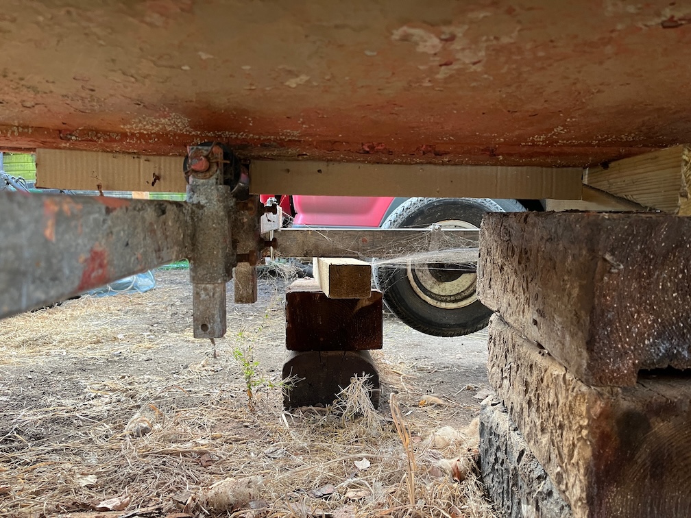
The recesses were cut so that a significant portion of the cardboard protruded through the hull as you can see above. I drew a line with a black marker pen against the bottom of the keel.
And removed the cardboard from the boat. Not very elegant but good enough.
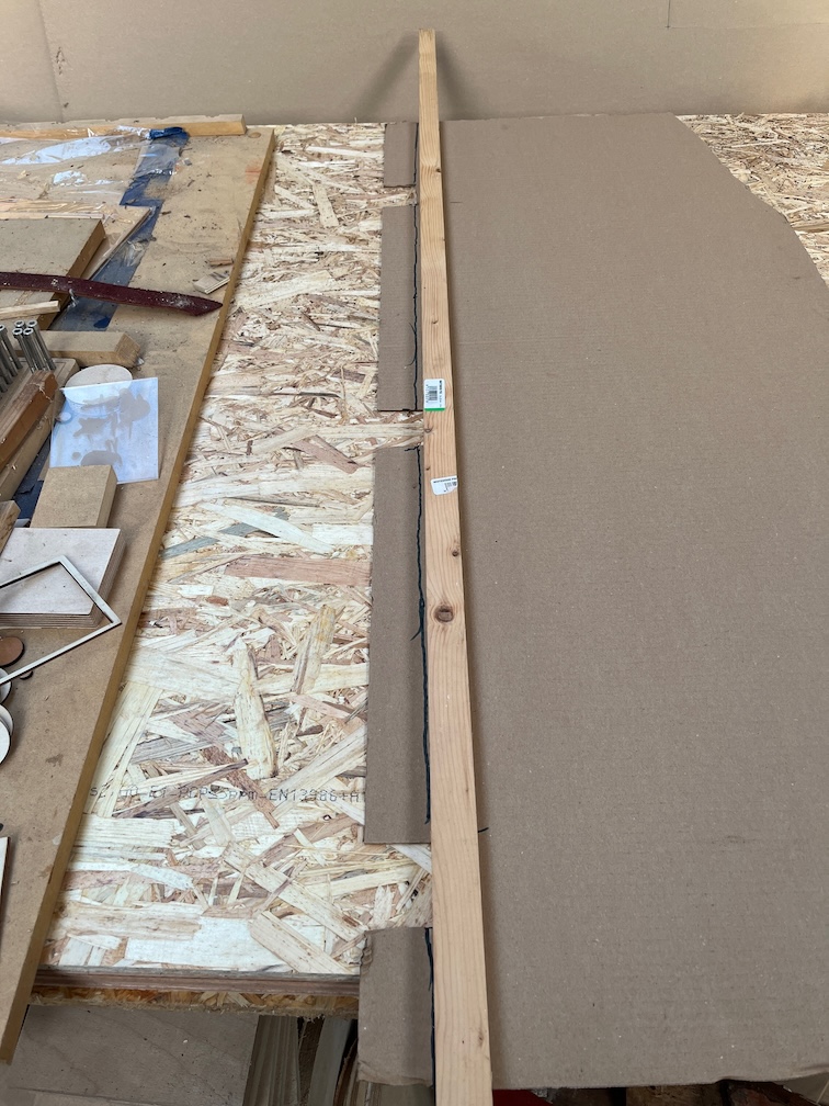
I used some panel pins and a batten to give me a fair curve and drew that.
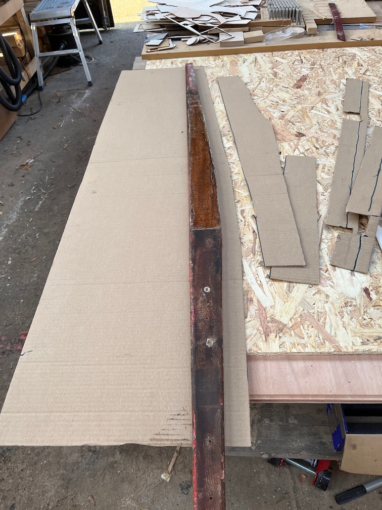
Like this. All I had to do now was to cut along this line which I did using a good pair of scissors.
That’s the bottom of the template done. Now for the top. The cardboard was clamped back in the slot but with the bottom curve resting on the lip of the keel slot. The top edge was then drawn with the marker and the whole thing returned to the workshop for cutting out.
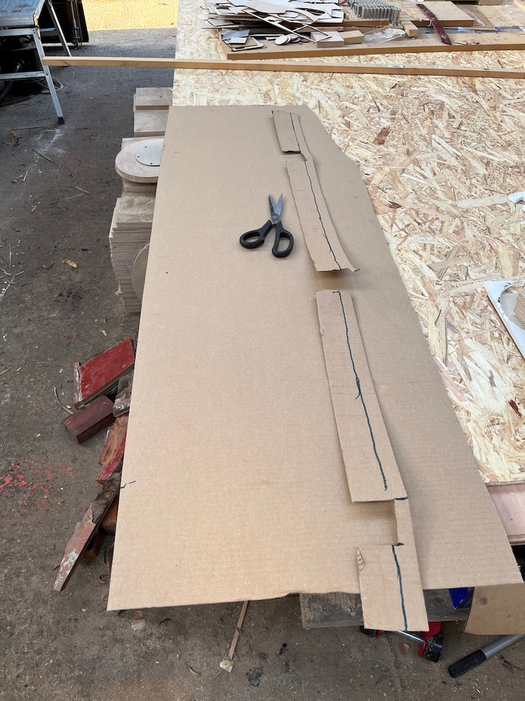
The top batten is quite beaten up in places, so the line is a bit wonky, but it is supposed to be three straight lines and that was easy to cut, this time using a suitable straight edge and a utility knife.
Looks good. So far nothing has gone wrong, so I decided it was time to take a break before getting the ends fixed to the centre part.
All this climbing in and out of the boat gets tiring.
Time for a cup of tea.
Some time later…
Having had a break, I found that I was beginning to lose the light, so I decided that once I had the ends fitted to the template, I’d call it a day for this part of the template task.
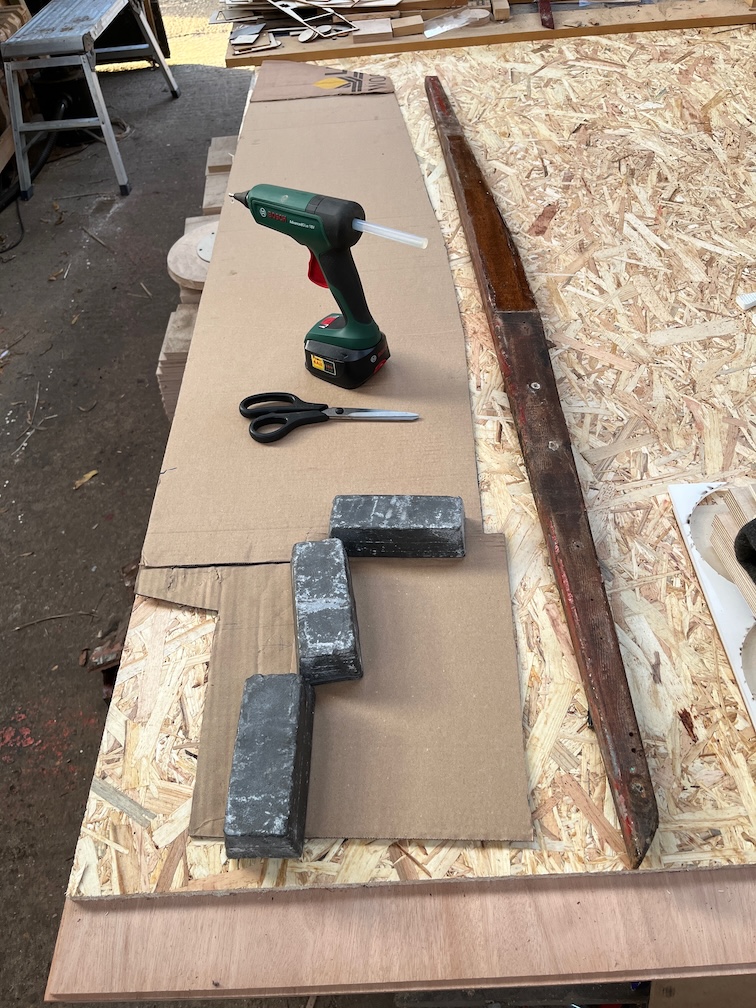
This is the first attempt. I’d put all three parts into position and c;amped them where I could, then marked where each one fitted. Then it was out with the hot glue gun and fix them all together.
What would be do without Hot Glue?
Once the glue had set I took the template back into the boat and dry fitted it.
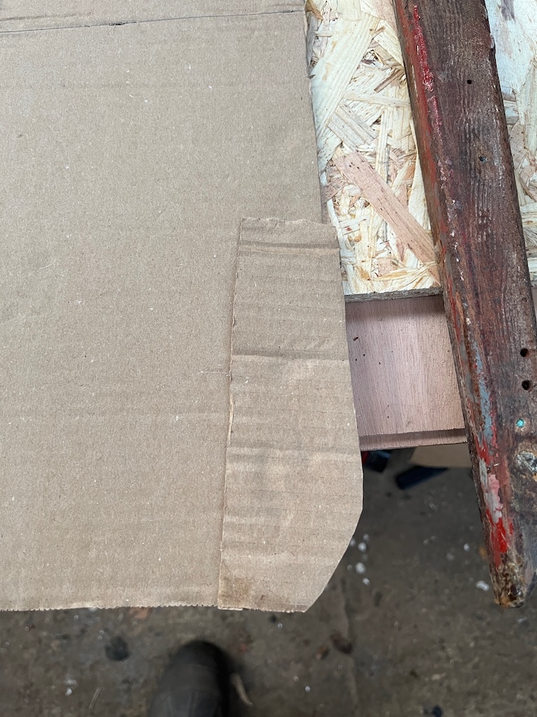
It didn’t quite fit, but here I had the first mistake of the day and cut the wrong bits off!
The fix for the front end.
And the fix for the aft end.
At this point the template fitted, or as well as a floppy piece of cardboard can but I was starting to make mistakes. So, despite being still light enough to do more, I called it a day.
The cutting and fitting of the plywood template can wait.
I will soon be reaching the stage of the centreplate case replacement where I need to make a cardboard template for the sides. However, before that can happen I need to chisel away some of the old case side that is between the fore and aft blocks and the keel.This is tedious as it requires me to kneel or squat in an awkward and cramped position working with a sharp 6mm chisel being careful not to go too far and cut away too much.
Not something I enjoy much so I decided to do something else first.
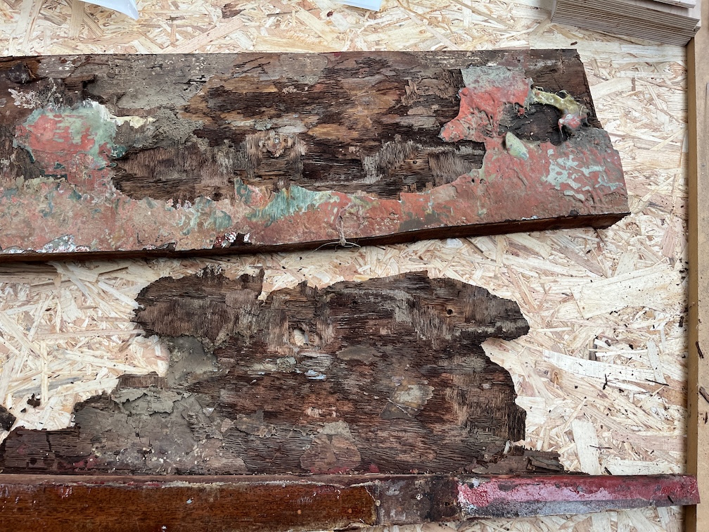
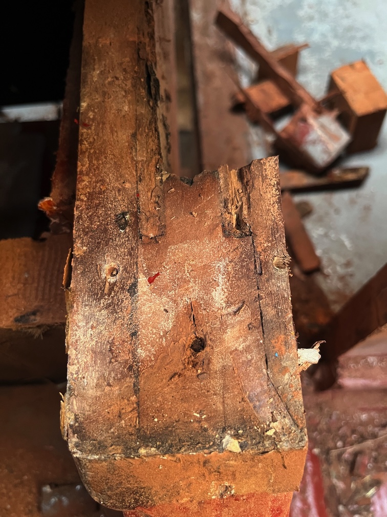
First task is to remove the top strengthening piece from the removed case side. I wedged the old and slightly less old pieces of plywood apart with a screwdriver and was able to pull the two pieces apart by hand. This is the result. The lower piece has the batten I want to retain with some of the original plywood attached and you can clearly see just how badly deteriorated it is. This did make it quite tiring to remove the plywood since it had no mechanical strength and only came away in small pieces. Still, after some time I had most of it removed.
This is the batten showing the outer face and the removed plywood flakes.
And this is the other side with some of the damaged plywood still attached. I decided that trying to get this off with a chisel was far to difficult and thus I was doing it the wrong way.
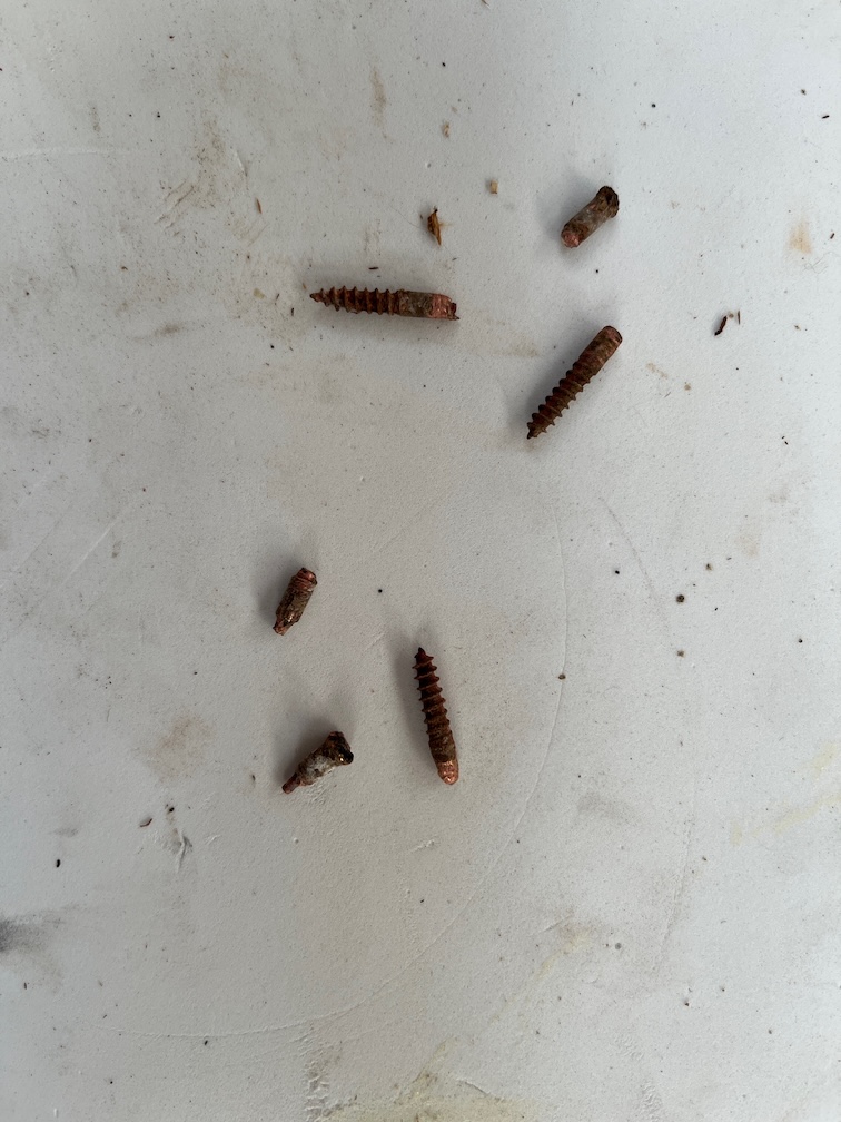
So, I removed the remains of the brass screws…
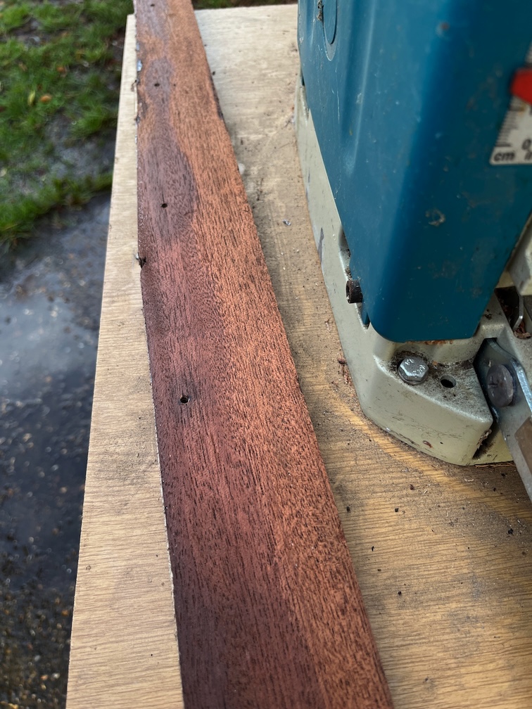
…and planed the rest off, the work of just a few minutes. I really should have just removed the screws and then used the planer instead of messing around with a chisel.
The result is very good.
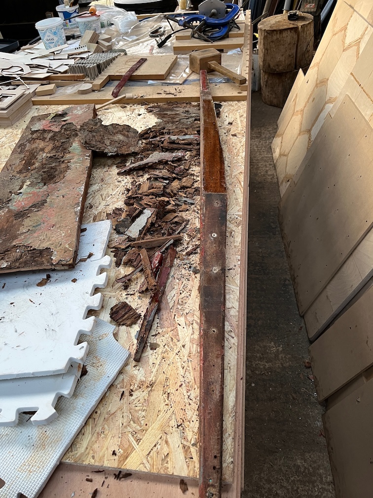
I still need to remove the diagonal brace, seen here, it’s the longer piece in the middle and this might be a little more difficult than the first piece as it has a rounded edge making the planing of the side opposite to the rounded side a little more problematic. Still, it will be easier than trying to get the plywood off by hand.
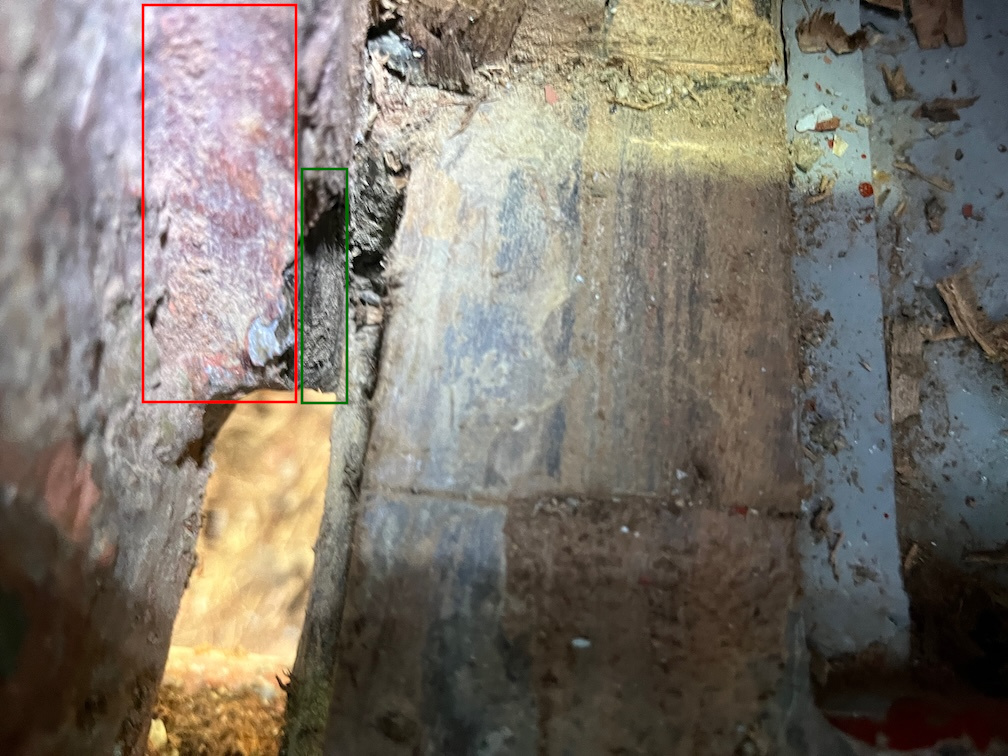
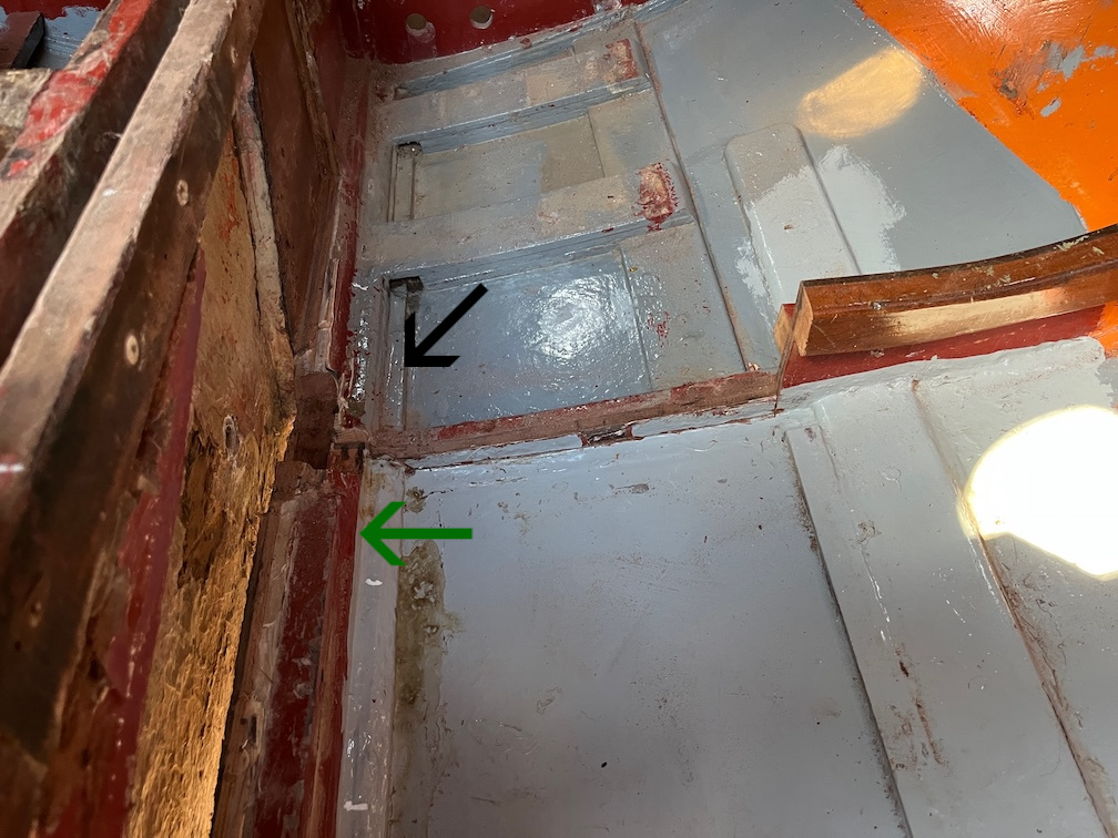
Following this successful task I turned my attention to the centreplate case. The bit highlighted in red is the forward block and the bit highlighted in green is the bit I have chiseled out! There’s not a lot of room in there.
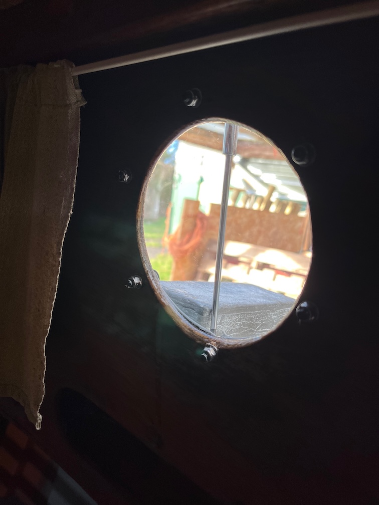
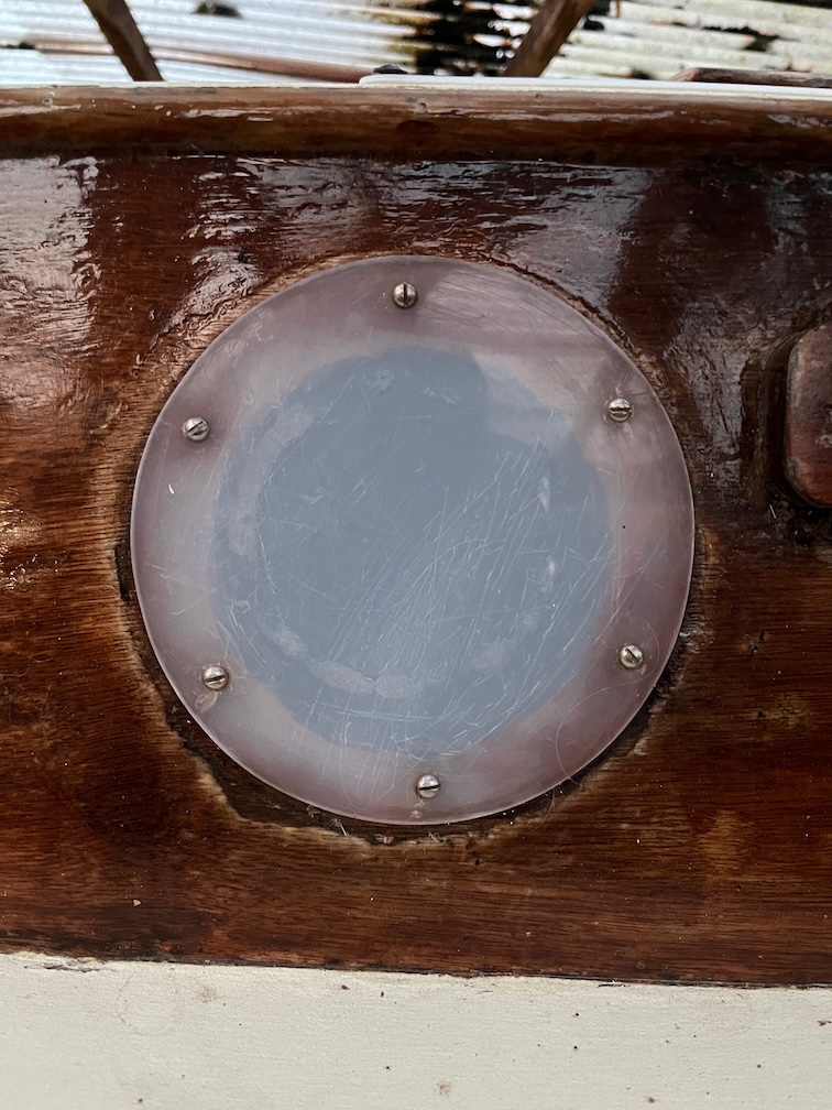
I turned my attention to the portlights after that. One side of each light was cleaned with Isopropyl Alcohol and a strip of Butyl tape applied making sure to cover the holes.
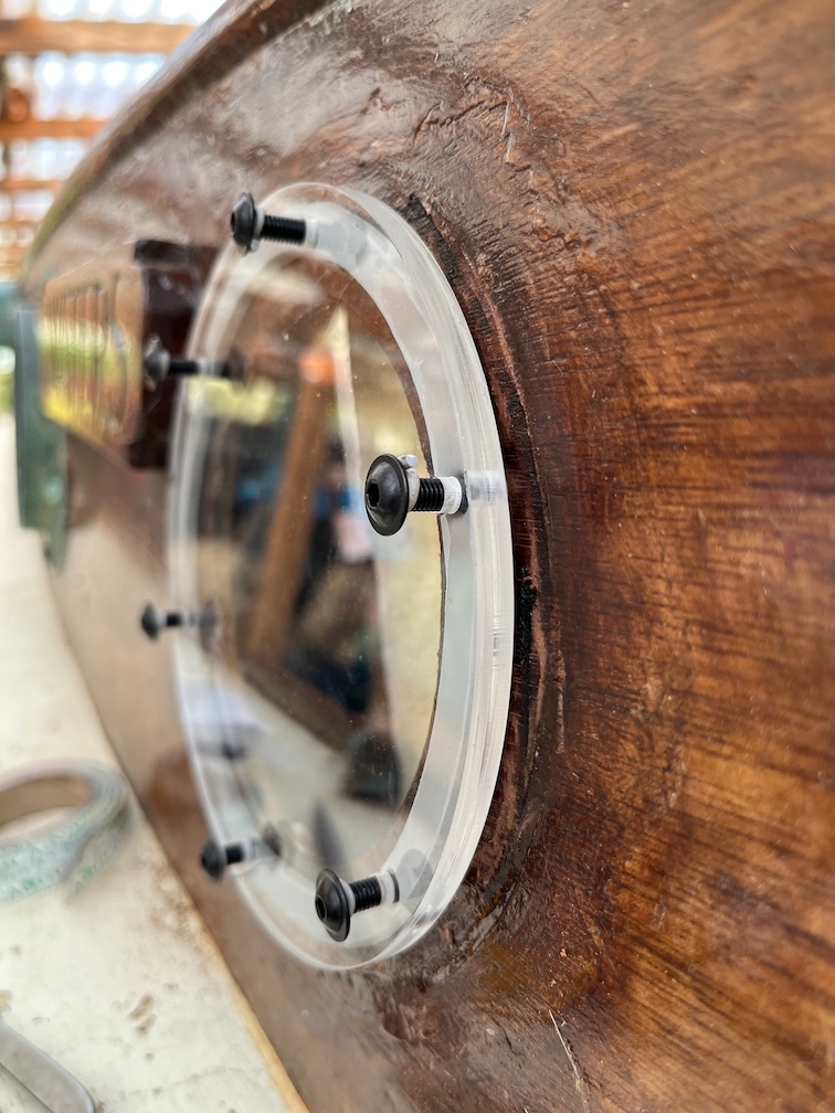
The light was then placed on the cabin side and six 5mm flanged bolts pushed through the holes in the perspex, the tape and the holes in the cabin side, but left protruding.
Some more Butyl tape was wound around each bolt just below the flange and the bolt then pushed in as far as I could by hand..
On the inside a washer and a self-locking nut were put onto the bolt and tightened up by holding a hex key on the outside and using a nut driver on the inside. That metal bar you can see outside is a hex key in the bolt on the outside being stopped from moving by a lead block so that I could tighten the nut up in the inside. Both forward lights were done with this lead block method but the two aft ones were close enough to the hatch for me to reach inside and outside at the same time, making the job a lot easier.
The tightening is done in stages so as not to crack the perspex. The bolts were tightened in opposite pairs so as to prevent bending to much. The nuts were not tightened up as far as possible as it is cold outside at the moment and the Butyl tape is not very flexible as a result. The nuts were done up about 60% of the way and then left. This will allow the tape to be compressed slowly an in a couple of days I’ll tighten then up to about 75% and then to 90% a couple of days after that. That will be tight enough to make a very good seal but to tight enough to squeeze all the tape out of the seal. This tape never goes hard, so leaving a bit unsquashed means that if there is ever a leak then I can tighten up the nuts a little to make a better seal. Any tape the squeezes out of the joint will be removed by scoring it around with a sharp knife and pulling the excess away
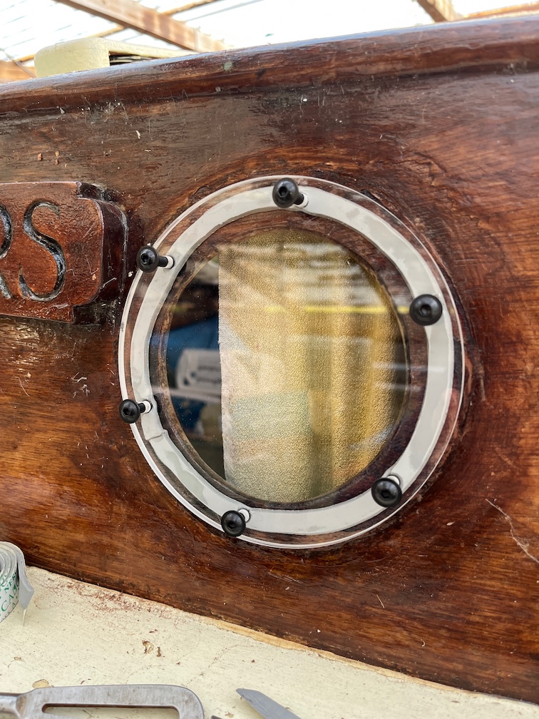
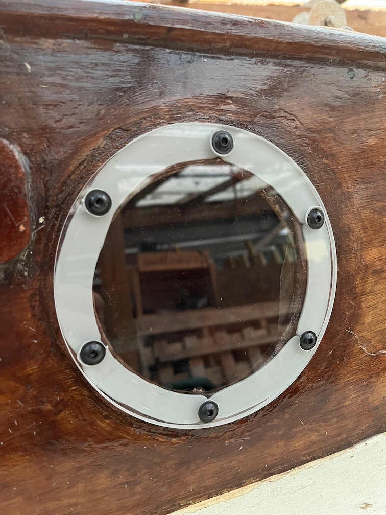
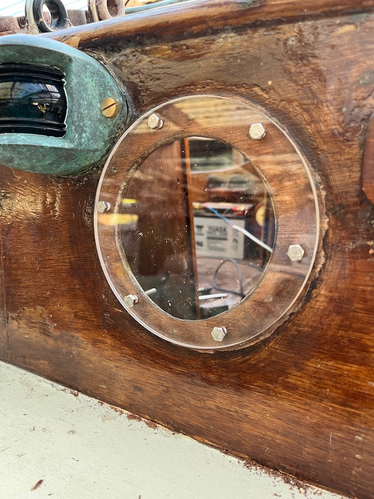
Here are the two starboard port lights. It would have been better if the Butyl tape were brown, but it isn’t so the portlights will stand out a lot more than they did before. It won’t affect the sailing performance, just the aesthetics and, being male, that doesn’t bother me much.
One of the good points about the way in which Charles Stock build the interior of Shoal Waters is that he slapped Mendix (or Mendex) over just about everything. That would be the equivalent of using thickened epoxy today with the exception that the stuff he used doesn’t appear to be susceptible to heat, unlike epoxy. So, unlike epoxy, you can’t make this stuff soft with a heat gun and scrape it off.
One of the bad things about the way in which Charles Stock build the interior of Shoal Waters is that he slapped Mendix (or Mendex) over just about everything. The only way to dismantle things done this way is to cut them out.
So far, the removal of starboard side of the centreplate case has removed parts that needed to be removed anyway, but has meant cutting through something that I would have preferred to not cut.
That’s the bulkhead that is shown here in the righthand side of the case.
This is what it looks like now. I’ve kept the piece that has been removed and I’ll epoxy it back in place when the new case has been installed. Although I may put in a new one that is the same as the height of the one on the port side. This bulkhead it supposed to stop the case from moving under the stress of the plate when sailing. The plate is 1.2m long outside the hull when lowered and that produces a lot of sideways force on the case due to leverage and I’m not sure that the small bulkhead Charles used is really enough.
The fairly careful removal is about to end. The aft end of the centreplate case protrudes into the cockpit and the woodwork around the case has to be cut out and removed. I have already made a start with a single “incision” to show the limit of the cut but now it is time to finish the job.
No finesse in this part of the removal, there are too many hidden screws to make this an easy job, so I just went at it regardless. Mind you, I didn’t cut of huge pieces at once, preferring to cut things away small chunks at a time.
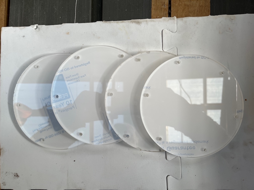
First break, make the replacement portlights.
I remove one of the old lights, scraped away the old sealant, drilled bolts holes through the old screw holes and put one of the replacement lights in place. I don’t have the correct bolts for this job, they are on order, so I just used some bolts that are too long to check how it looks.
The USB charging ports of the charge controller only supply 500mA total and if you try to take more than that, it takes away power from the controller itself and that stops working. So I bought some blanking plugs.
I’ll probably fix these in using some hot glue the they don’t fall out. There’s no reason to use these sockets as I’ve wired in eight others that will supply s good amount of power.
Back to the cantreplate case. I cut away the top cover to reveal the top of the aft end of the case. It came away quite cleanly and you can see the soft plywood of the case where it is inset into the aft block.
Then it was more work on the sides. This lump is the plywood added by Charles and has to come off.
A while later and that was removed and I could see the glue line where the plywood of the side is glued to the aft block. I’ll need to tidy this up and there’s still a lot of the plywood left and my chisel work is not that good, so I’ll resort to using a sander for that bit. But this does show clearly where the plywood ends.
Finally, for today, I remove the supporting battens back to the keel. Well, almost. The one added by Charles is okay, but the original one is very wet. Not rotten, just soaked up a lot of water. I’ll let that dry for a bit and then sand the rest of this and the paint back to the top of the keel. I’ll probably need to take this away completely as I don’t know how far the wet wood goes.
This is the other end of the battens, so not a lot to remove and since the wood is very wet, it is probably a good idea to remove it and replace it with new wood. It will be interesting to see how the keel is under the batten. It has been glued in place so the water that was soaked up by the batten probably hasn’t affected the keel…I hope!
That’s the end of the centreplate case work for today, although not the end of the tasks for the day. There’s not going to be enough light to continue the case removal after I finish work but enough to do a few more port lights.
So, here’s the process. Select the light to be replaced.
Remove the screws. Notice that the old light doesn’t fall down as there is some sealant between the perspex and the cabin side.
Pretty good stuff, but it has to be scraped off.
Interestingly, once the sealant has been removed you can see that this light has already been replaced three times before. There are the screw holes for the light just removed, two sets of screw holes that have been filled in and the remains of some screws that have been sanded down flush with the wood. So that means that this new light is the fifth one !
Then it’s drill the holes and put the light in with temporary bolts.
I managed to get two more done but the light was fading fast and so was the temperature. Clear sky, Winter and once the sun sets the temperature plummets.
Still, a fair bit done during coffee and lunch breaks.