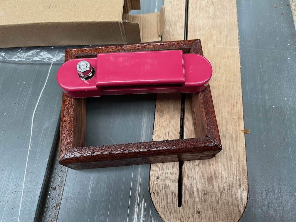
The bus bars arrived late afternoon yesterday and to my dismay, they are not the correct size. I bought this pair of bars to fit inside the in the switch box.

These are the dimensions and you can clearly see that the overall width of the bars is 105mm.
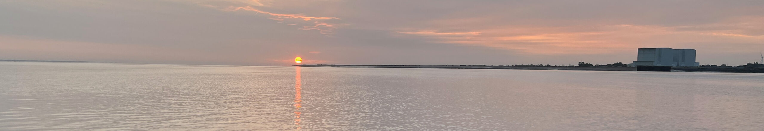
Now the width of the space in the box is 110mm so the bar should fit, but as you can see, it does not. Each bus bar is, in fact, over 140mm long. Looking at the catalogue again I found that the 105mm is the length of one of the smaller bus bars and the given drawing is incorrect.
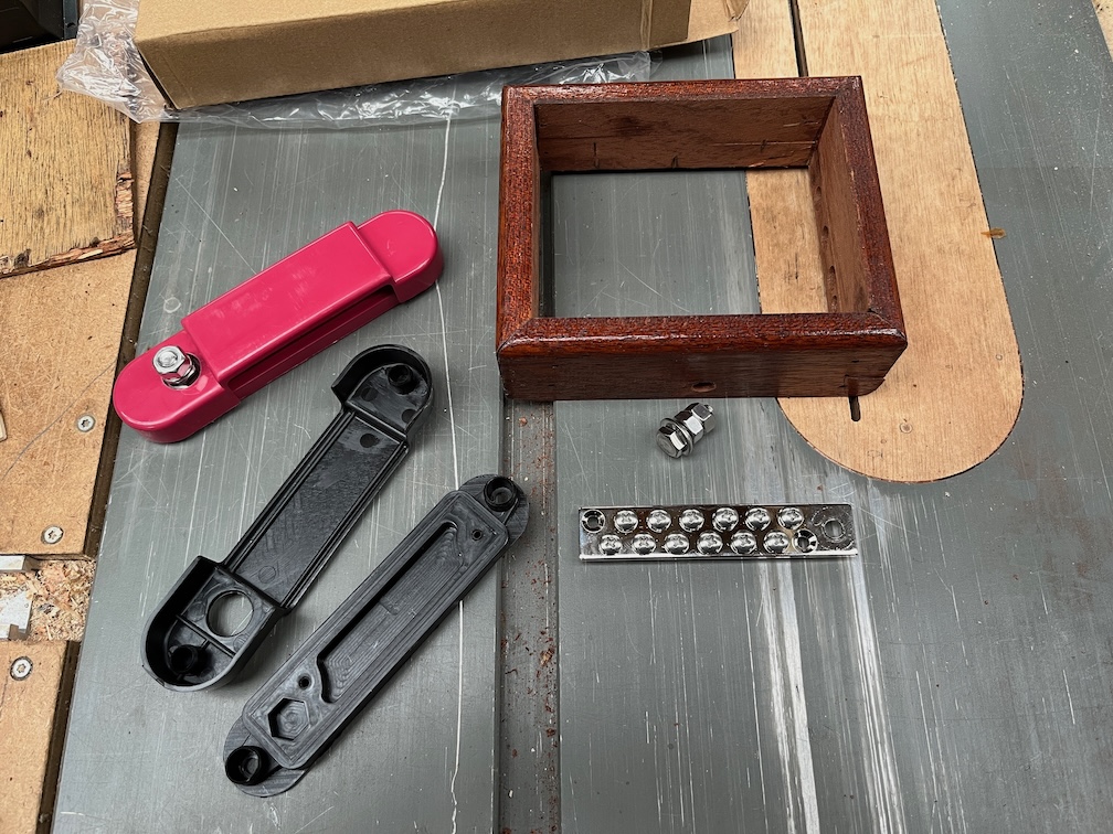
However, if I remove the metal bus bar from the plastic housing, it is now small enough to fit.
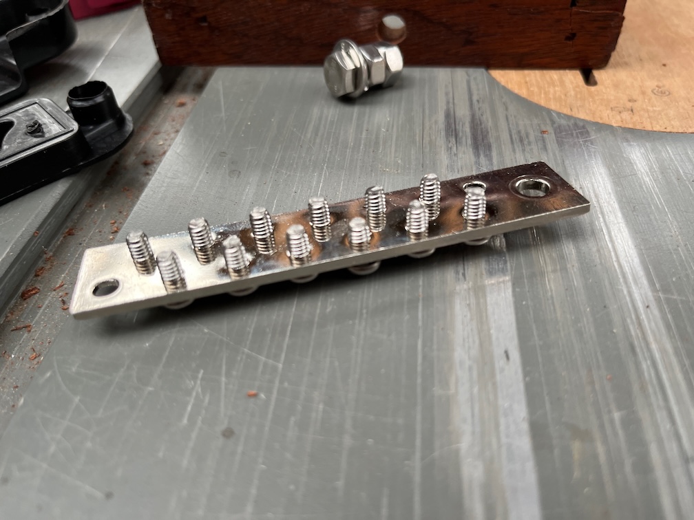
The bolts on the bars extend about 5mm below the bar itself and if I were to mount this inside the box as it is, then there would be a significant problem.
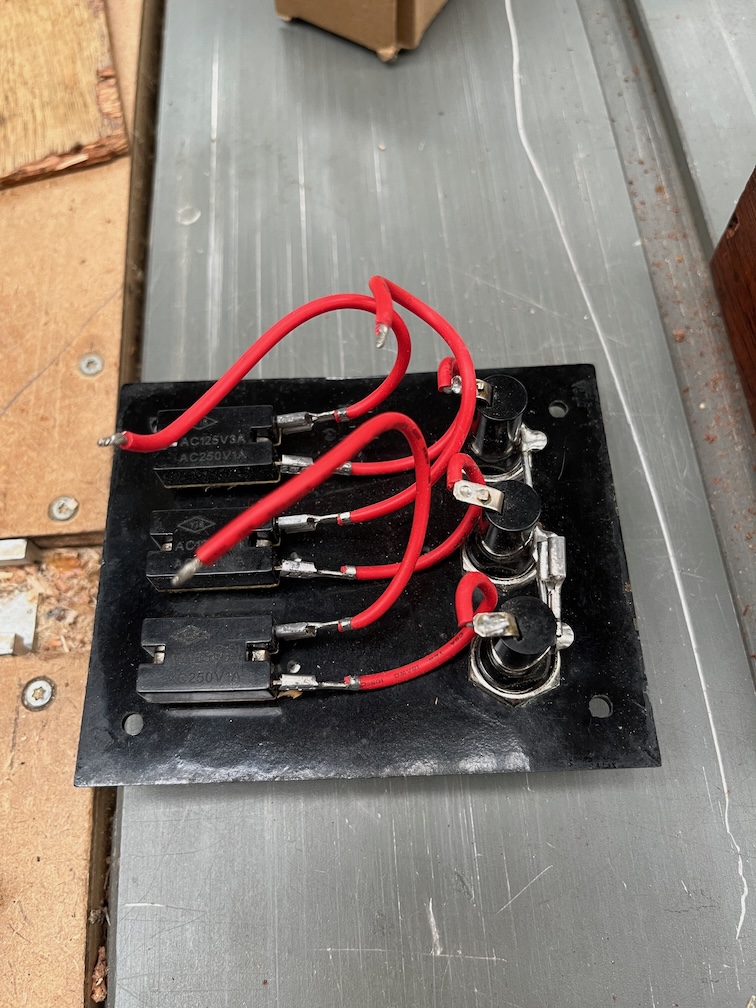
Some of the wiring on the front panel extends into the box quite a distance and even with the connections bend over as much as I can make them without breaking them, they would touch the bus bar and that would cause a short. Not a good idea.
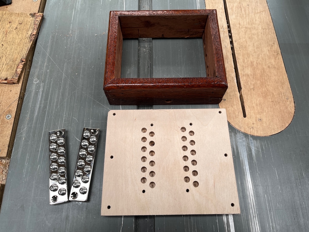
So I spend last night designing and part of this morning making a back plate for the box. It is 15mm thick and has recessed holes for the bolt protrusions. This will mean that the bus bars will be unable to touch any of the current wiring. I may even have space to put in a cover for each bar to prevent anything untoward happening.
The drawback is that the switch box is now 15mm taller than it was before and will be another 3mm taller still once the front plate is made. More on that later. Still, I feel that this is a small price to pay for having proper, protected electrical connections.
Each bus bar can hold 12 connections and so far I have the following for the negative lead:
- Port nav light
- Starboard nav light
- Stern light
- Compass light
- Cabin lights
- USB charging hubs
And these for the positive lead:
- Compass light
- Fuse bank
- Cabin lights
- USB charging hubs
I don’t plan to have any other connections, but having a few spare is always a good idea. I may want to run a power lead for a radio, for example. Not a marine radio, a domestic one for listening to things like the Met Office Forecast.
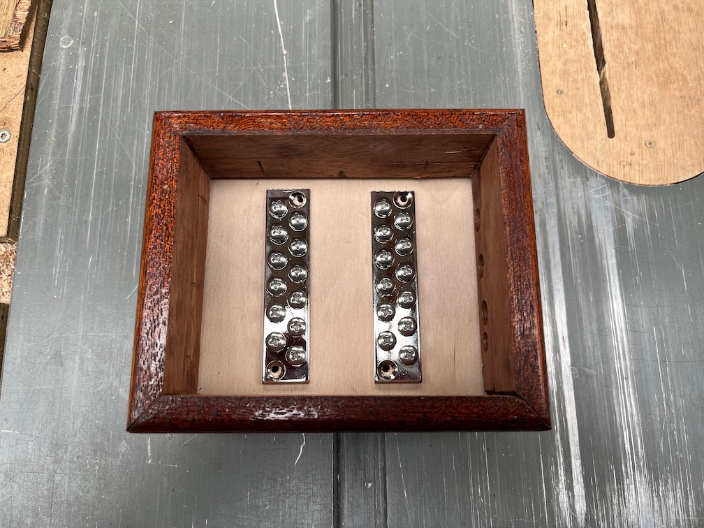
The back plate has been stained with two coats of a dark stain, like the charge connector back plate, and one coat of varnish has been applied. Both the back plates are made from Baltic Birch plywood which is a high quality plywood, but not intended for exterior use without treatment as the glue holding the veneers together is not waterproof.
The stain is to darken the very light colour of the wood and the varnish is to protect the wood from any damp. I expect to apply around four coats to all the surfaces, then lightly sand the visible edges and give them another two coats. After that, they may be fitted into the cabin, although not the final fitting, and the wiring adjusted to fit the new arrangement.
It is, however, November (already) and staining and varnishing in the workshop is a long process due to the extended drying time. So, I’ve been staining in the workshop and bringing the pieces into the kitchen where they are placed on the Rayburn to dry. Once the staining was completed, both pieces were taken into the workroom where the varnishing is done. Here the procedure is to apply a coat of varnish all round, using screws as standoffs and once the varnish has cured a little, the work pieces are returned to the Rayburn to complete the curing. Even so, it is a laborious process especially since the next part, adjusting the wiring, cannot be carried out without the controller and switch box mounted.
Oh well. That’s boat building for you.
Once the wiring from the controller to the switch box, the other wiring and the battery cable to the controller are done, I’ll mount the new solar panel and route the wiring to the controller. Again, this will not be the final fitting as there is still a bit of work to be done filling holes and repainting to done to the cabin top, but that will be enough to verify that the new wiring layout works.
Time for a cup of tea.