Unfortunately, the parts I need to finish the installation of the cabin light didn’t arrive until after dark, so that is put off for a day. I did manage to get some work done, just not everything I wanted.
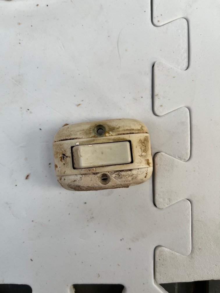
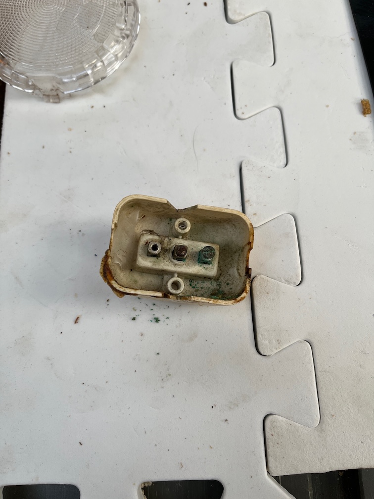
This is the original cabin light switch. It is very mucky as you can see.
And the terminals on the inside are a bit corroded, but it still works. I don’t know whether to be surprised at that or not. Still, it works, so it will be reused although not without a fuse in the circuit, just in case.
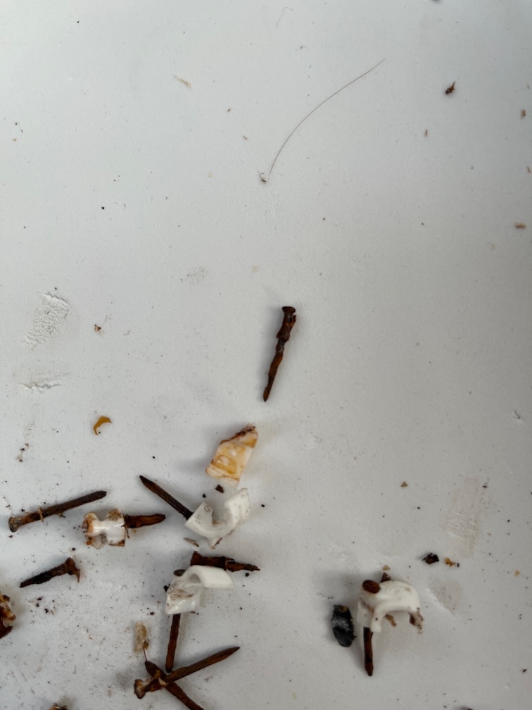
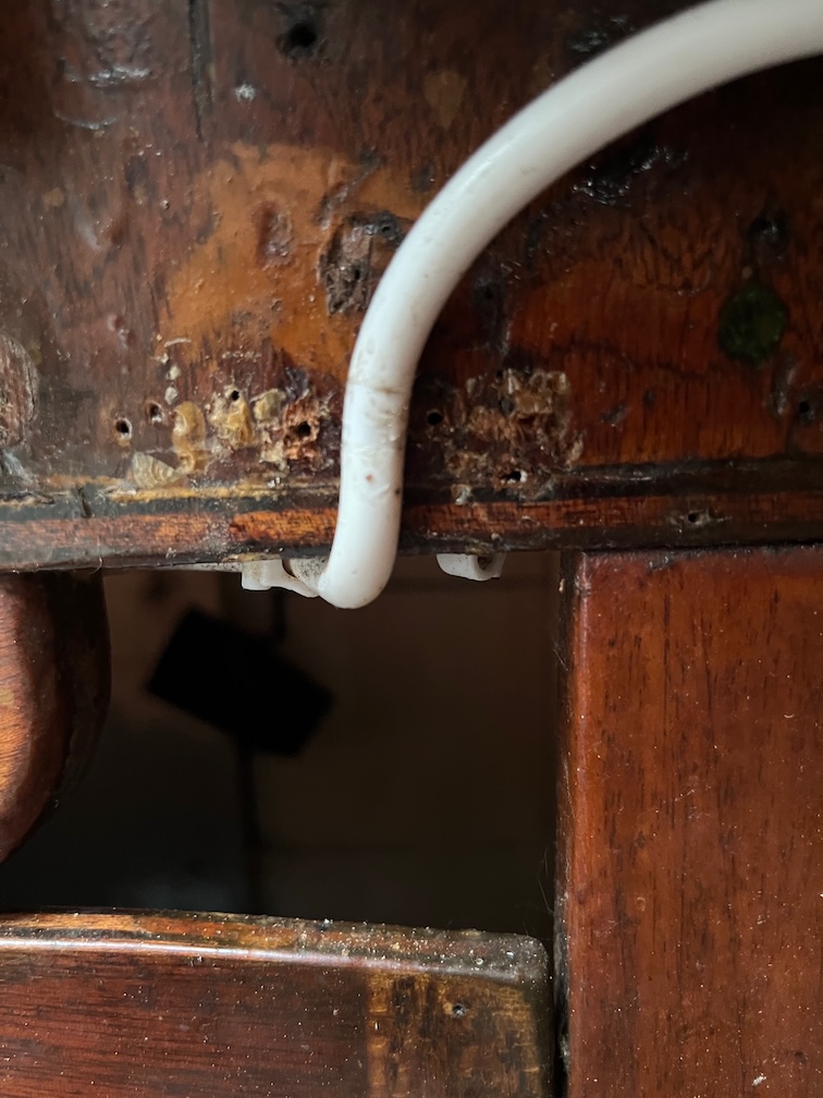
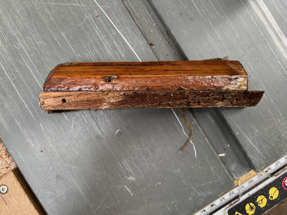
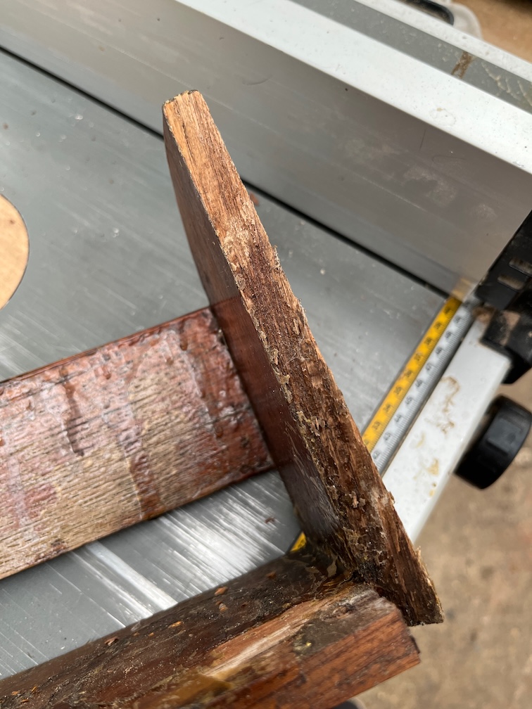
This is the reason why you don’t put cable clips into wood with steel pins in a marine environment. Some of the pins have completely wasted away in the wood and others have split the clips.
This one is partially wasted and it split the clip.
The cable was also disintegrating, as I pulled it out of the clips my hands became sticky with decomposed plastic and the cable broke open in places exposing the copper wire inside. I suspect that the cable was pre-1977 since it had red and black interior cables. Still, it will be replaced with newer cable.
I also drilled the holes in the cabin top for the light base screws.
These bronze screws are screwed in from the outside…
… and into the light base on the inside, suitably cut down such that they do not protrude through the base.
I had to remove the polystyrene tiles in that section before doing this. I don’t know what Charles used to glue the tiles to the boat but it is really tough. So far the wood under the tiles ss still good although the paint is coming off in a few places. Eventually the underside of the cabin top will need to be repainted, but that might not happen in this cycle. The aim is to get Shoal Waters back in the water for next season and that will mean not doing some of the tasks that are not necessary.
Still, things are progressing. The marine plywood from Robins Timber was delivered yesterday afternoon, four sheets of 6mm and two sheets of 4mm all full sheets of 2500mm x 1220mm. Most of that is for the new, lightweight dinghy that also needs to be built before Shoal Waters is put back in the water unless her mooring is one close enough to the shore to be able to walk through the mud to board. Hopefully this will be the case. The dinghy will then be used for getting to the boat when she is afloat and also using it as a sled when transferring heavy items to the boat. Simply put them in the dinghy and push it across the mud.
Having found yesterday afternoon that the light faded too fast after work to get anything significant done inside the cabin without interior lights, which I haven’t installed yet, I did some work during my lunch break.
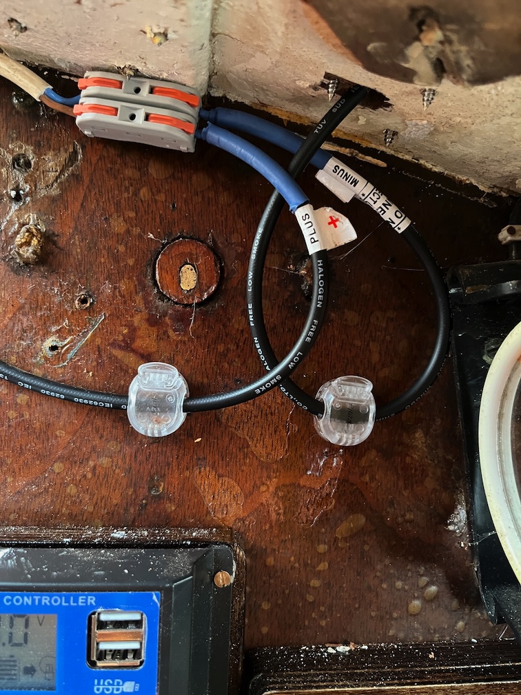
I ran the white cable for the solar panel and clipped it into place. Since the black cables are very stiff I think I’ll not bother to cut them any shorter than they are now, they will not go round a much tighter bend than you see in the photo, and use the cable clips to hold them against the upstand pretty much where they are now. I have some clips that open and close and I may try to use these for the black cables since I’ll need to take the solar panel off periodically and using the nail-on style of clip is not suited to that type of use. The disadvantage of the reusable clips is that the stick on rather than screw on and that might not be a good solution here. I’ll have to see if I can screw them in place anyway.
Some time later…
Well, the answer to that question is yes, I can. The double-sided tape on the clips held them in place and then I could screw them to the upstand without having to try and hold them in the correct position at the same time as trying to screw them in.
Mind you, I did have to drill a suitable hole in the bottom of the groove in which the cable runs, but that was not difficult using new, sharp bits and a drill running at a slow speed.
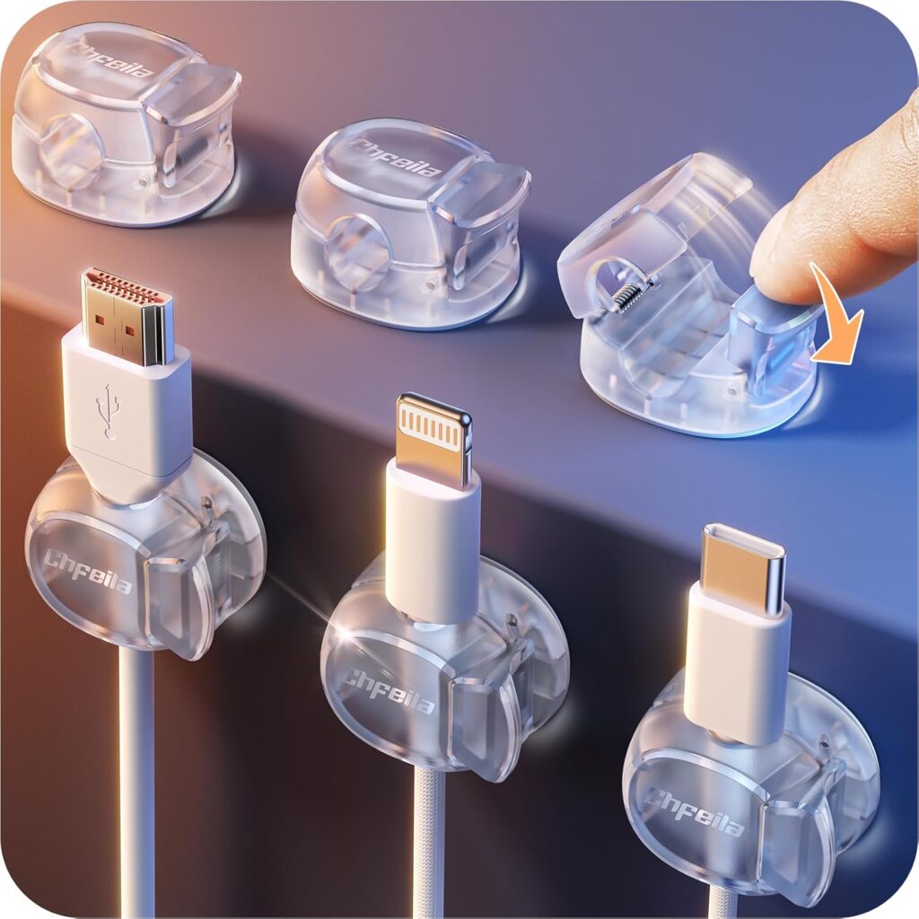
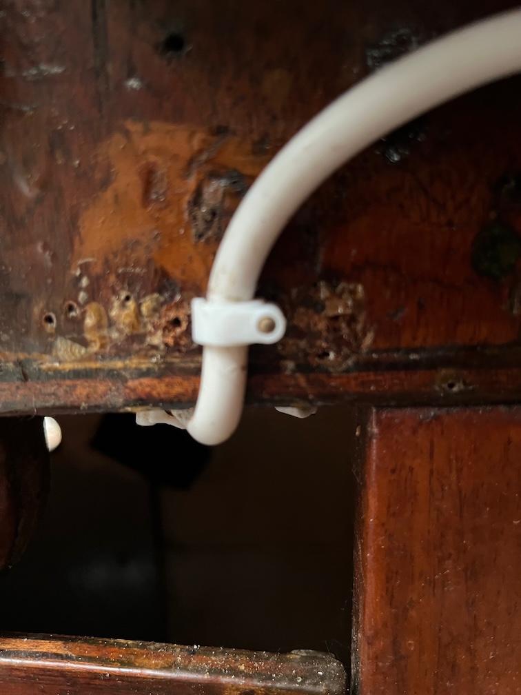
These are the clips I used. they are called Chfeila clips and I bought them from Amazon I have used them in a couple of places in the workshop now and find them very good. They seem to stick quite well in the dry workshop, but I wasn’t sure that they would in a marine environment, hence the screws. I used bronze screws for the job and that seems to have worked well. I’ll be using these again. One place where it is exceedingly hard to hammer in the normal cable clips is under the bridge deck and I’ll be able to use these for the compass light cable which I have removed.
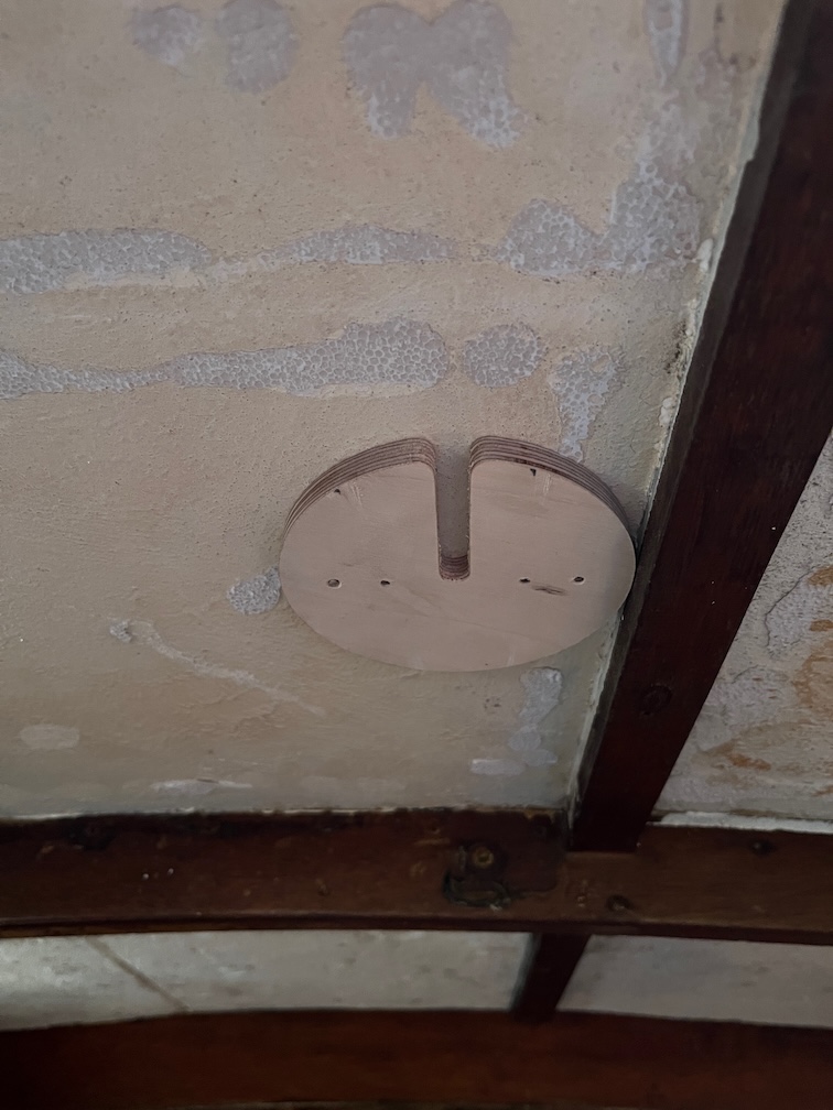
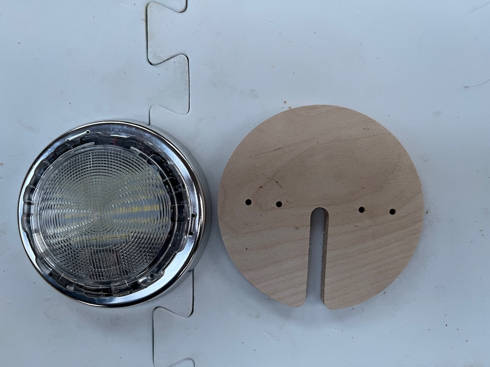
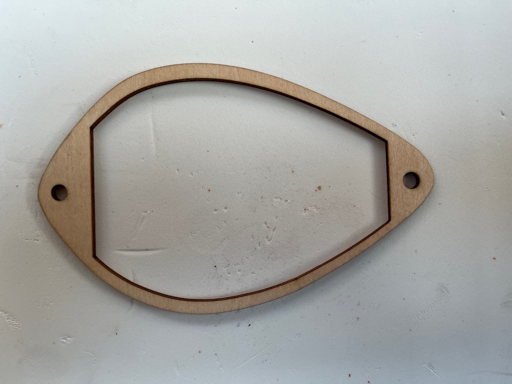
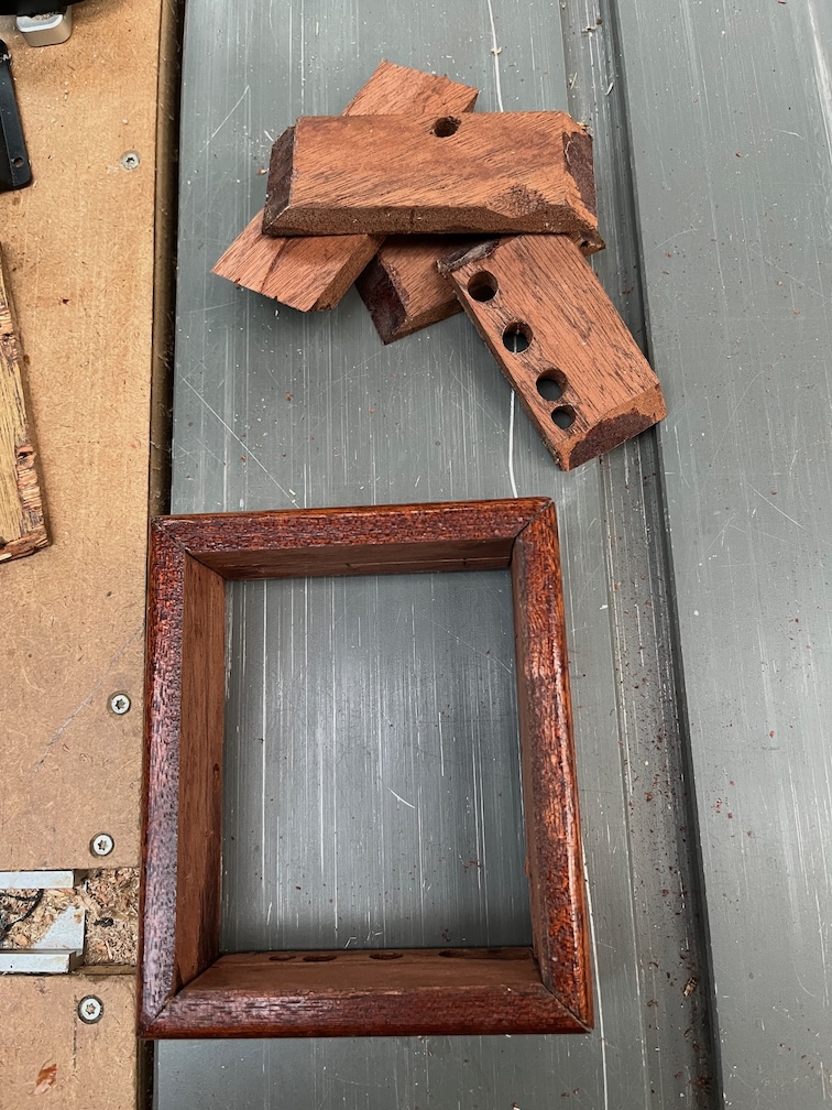
The next task is to mount the first main cabin light. This will be sited in the centre of the cabin top width-wise and just forward of the companionway. The issue here is that there is a narrow beam running fore and aft, so the light will have to be offset slightly otherise the light and heads will meet in the middle !!!
I’ll need to make a base that will allow the light to be screwed to the underside of the coachroof..
So, armed with light and calipers, I made various measurement and then drew out the required parts on the CAD program.
The drawing for this simple shape takes less than ten minutes to create and once that has been imported into the CAM software and the code for the CNC Router done, another ten minutes, I’m ready to cut.
I’ve cut this out from 9.5mm thick Baltic Birch plywood on the CNC Router, around fifteen minutes to set up and cut out. I do like these CNC tools, they save so much time. Now I’ll be able to install the first light in the cabin, probably tomorrow. The two outer holes are for the screws holding the base to the cabin top which will be screwed in from outside, and the inner two are for the screws holding the light to the base.
If all goes well I should have light in the cabin sometime tomorrow.
One of the things I say frequently enough to make my wife roll her eyes is that it’s good to have the right tools for a job. Yes, I can do things without the correct tools, well, some of the time, but other times I can not.
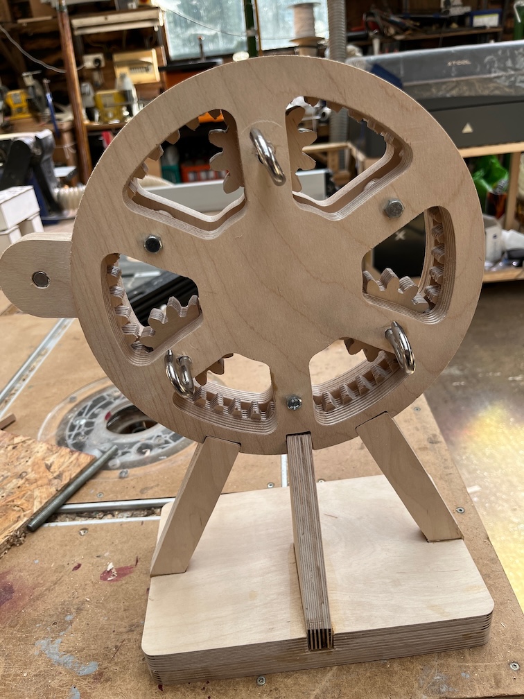
Take this beastie, for example. It’s the winding head of a rope maker Under normal circumstances not only would I have not made this, but I would not even thought about making one. My carpentry skills are just not good enough to make the gears.
However, I have a CNC Router and I started doing mechanical drawings back in Grammar School, although back then it was called Technical Drawing or TD for short. I’ve been using CAD drawing packages pretty much since they first came out for personal computers. So it was an easy job to draw up the plans for one, use a CAM package to create the g-code for the CNC Router and away I went.
Well, the same thing happened to me again whilst I was trying to replace the bulb in the port side nav light.
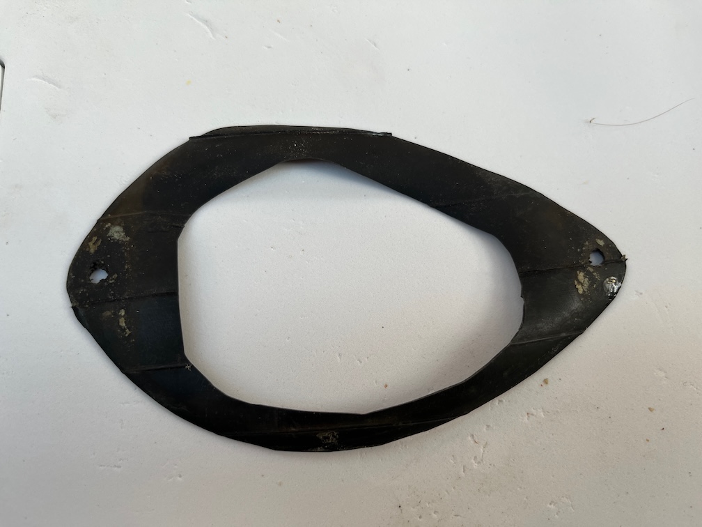
This light had a gasket, unlike the starboard one which had sealant, and the observant among you may have noticed that this has been cut out of a bicycle inner tube. A pretty good idea, but rough. Not that I could do any better with a sharp knife and a pair of scissors, I hasten to add, but I also have a Laser Engraver/Cutter and figured that using this I could do much better.
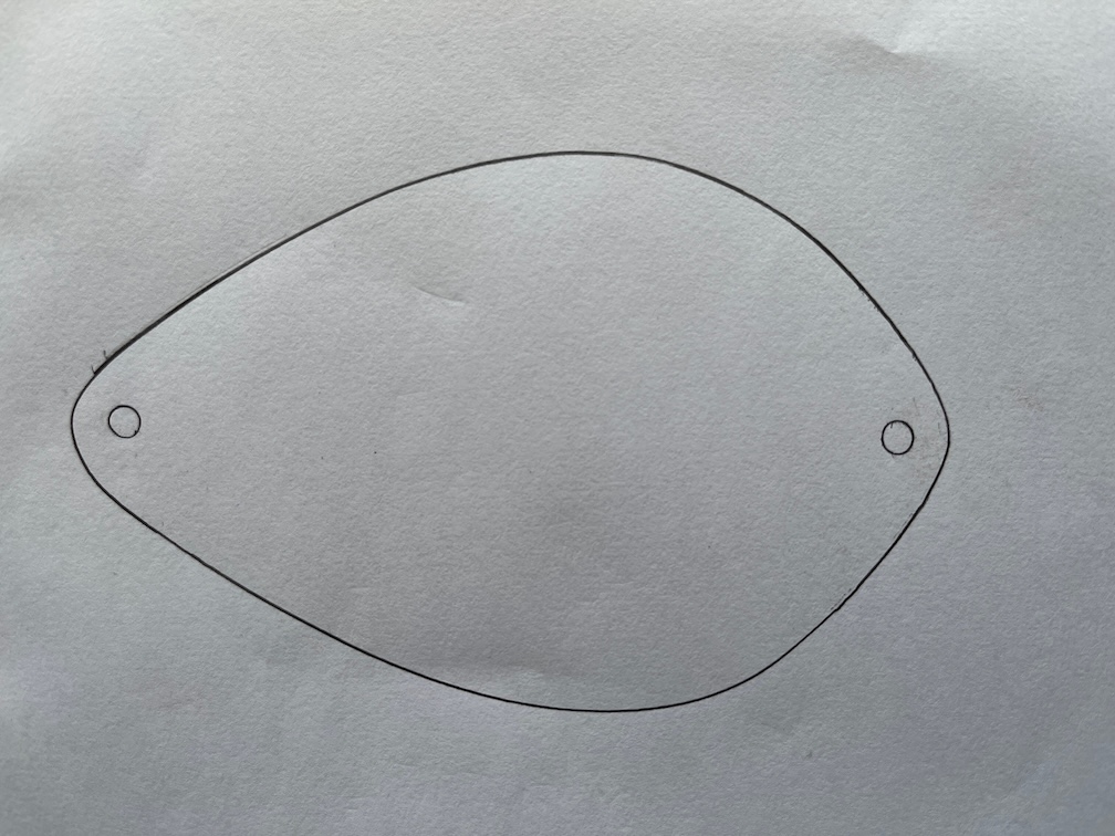
I took off the light housing, drew around it on a sheet of paper, photographed it and loaded the image into my CAD program. Using the various drawing tools I created the drawing.
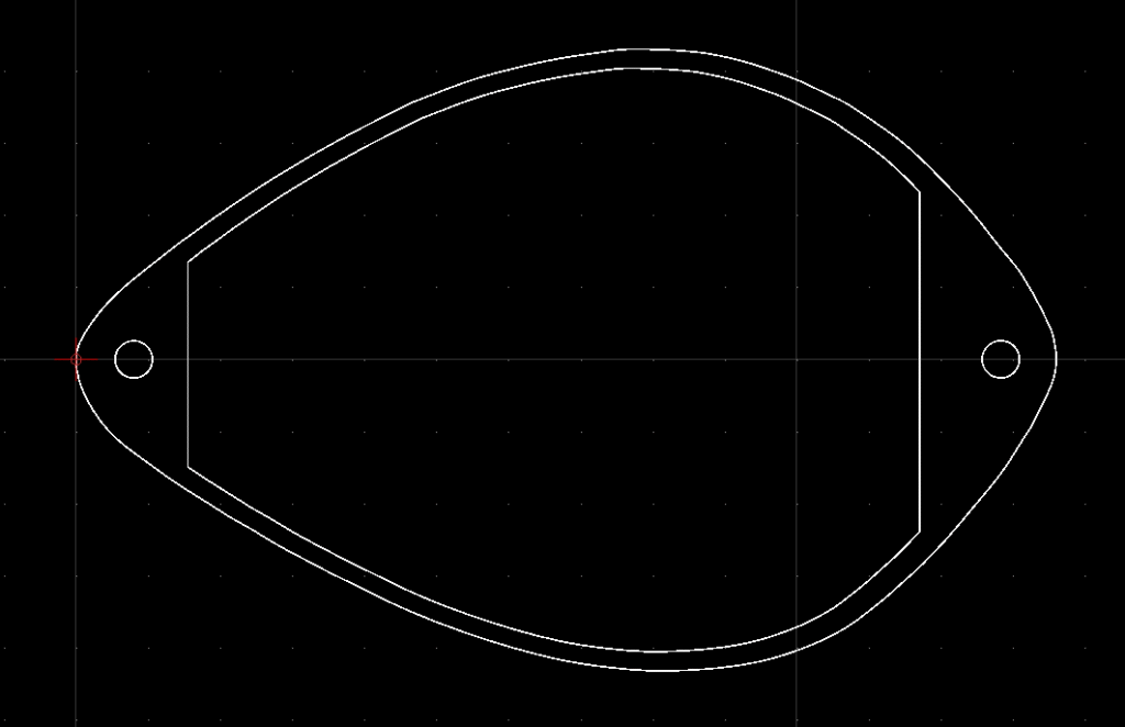
This was exported to the CAM software and thence to the laser cutter. I used a piece of thin plywood to cut out a test piece as the gasket material I ordered will not arrive until tomorrow.
This is the first attempt which is pretty close. The outer edge, the holes and the two vertical straight line are spot on, but the thickness of the upper and lower parts are too thin. Looking back at my measurement I noticed that I’d messed them up.
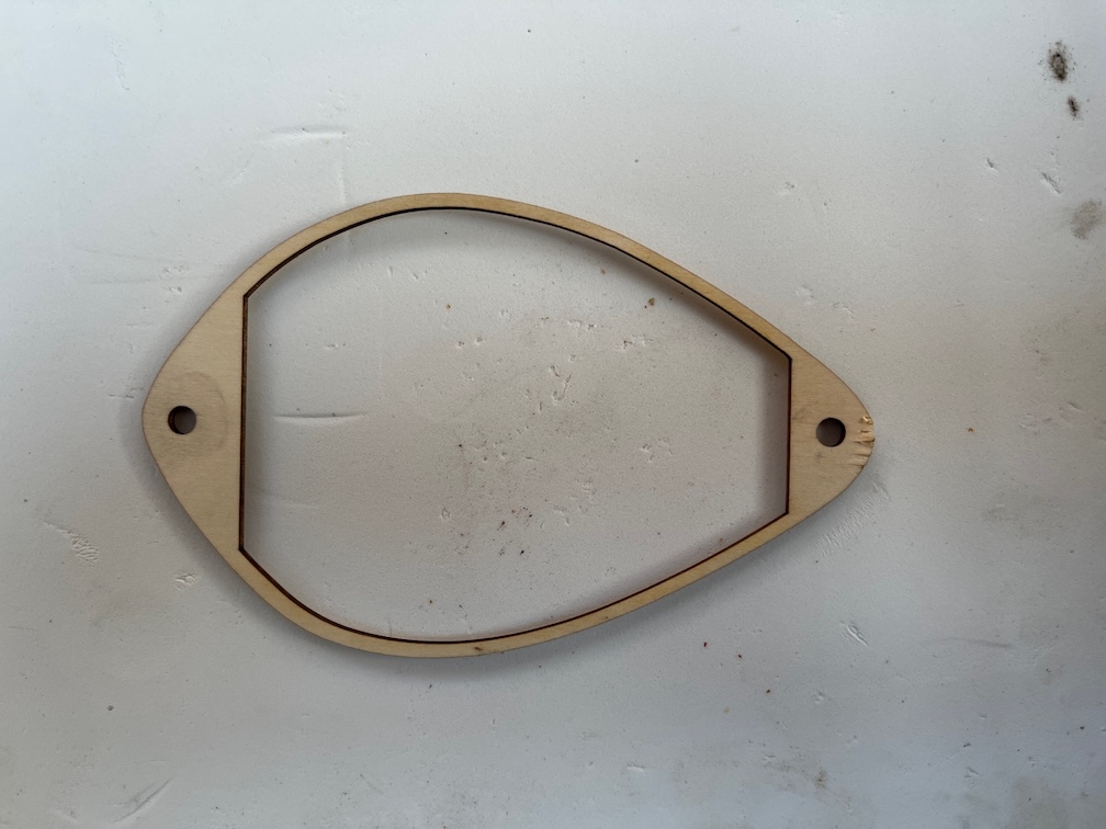
After revising the drawing this was the second test piece.
This one fits perfectly. When the neoprene arrives I’ll be able to cut out two gaskets for the nav lights that I know will fit and the really good thing is that if I ever need to replace them, I already have the drawing, ready to go and tested.
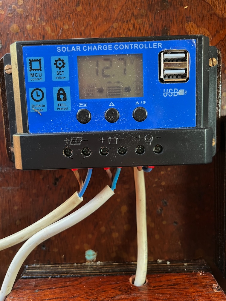
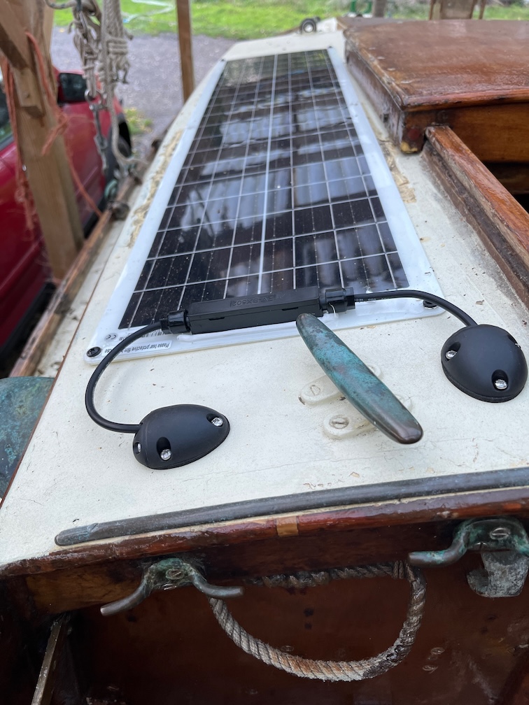
The task for today was to connect the solar panel to the controller and check that it works as expected.
It didn’t take long do and it looks very rough, but it’s very temporary, so how it looks right now isn’t that important.
On the inside the controller is indicating that the solar panel is connected and is providing power to charge the battery, even in the Hay Barn. This has a clear perspex roof so light can get in but it is not in the direct sunlight so the fact that it is still charging the battery is very good news.
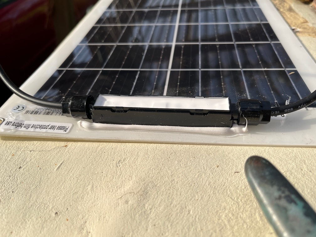
The problem with the solar panel is that the cables are very stiff. I took the top off the connected housing to see if the cables could be replaced but the housing was filled with a potting compound so that is out.
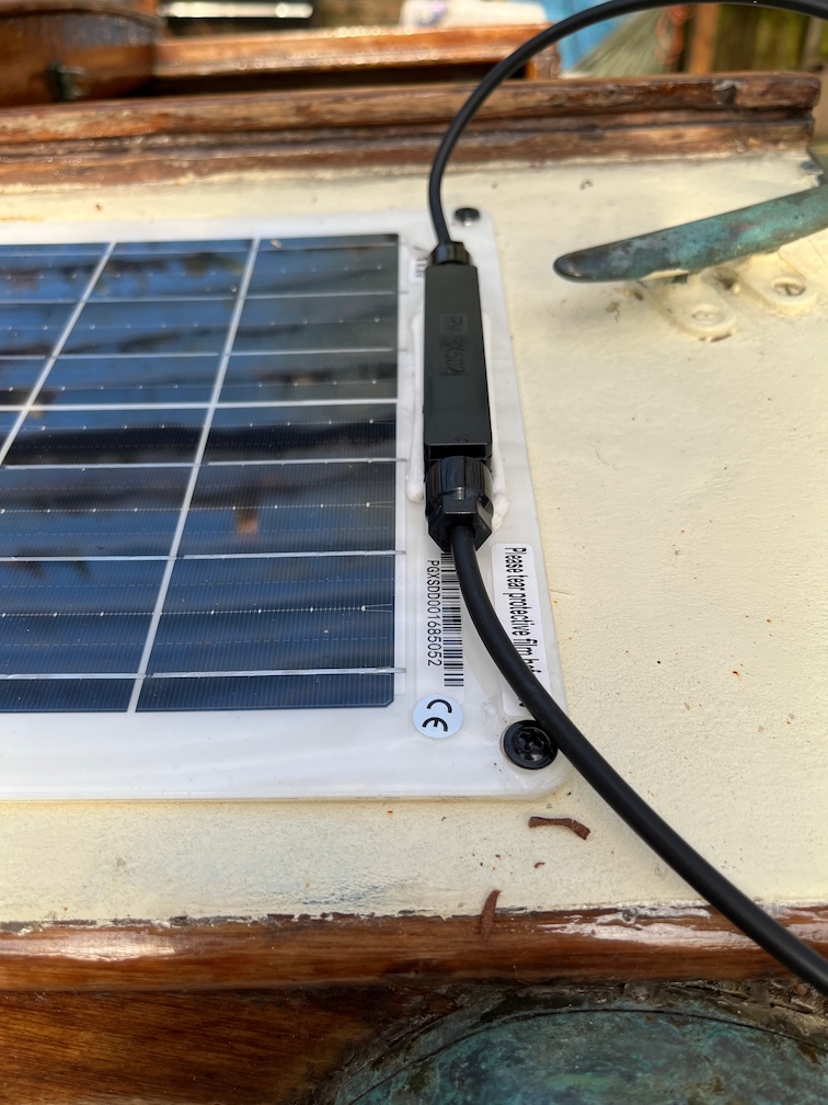
I did have to screw the panel down as without some sort of fixing, the panel would easily blow around in the wind. These screws are in the right place for the final fixing, but not the proper screws just yet.
The panel takes up all the port side of the cabin top but that’s not a problem, it doesn’t get in the way of anything important.
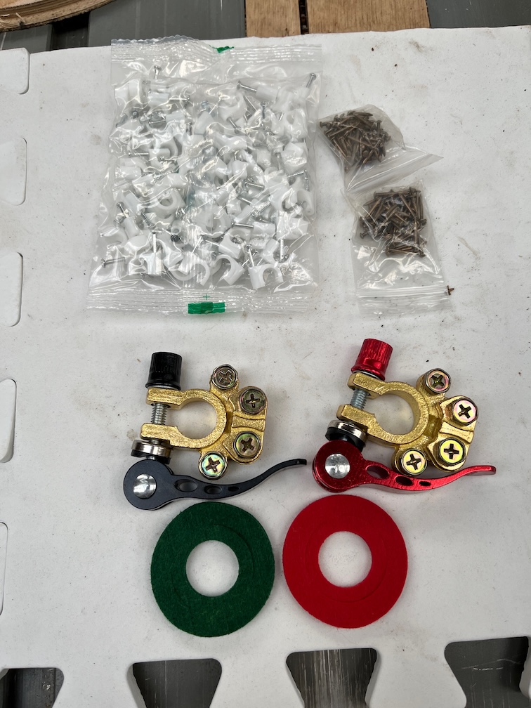
After lunch the next lot of parts arrived and I was able to continue the work.
Two clamps for the battery, some 7mm cable clips and some brass 15mm pins.
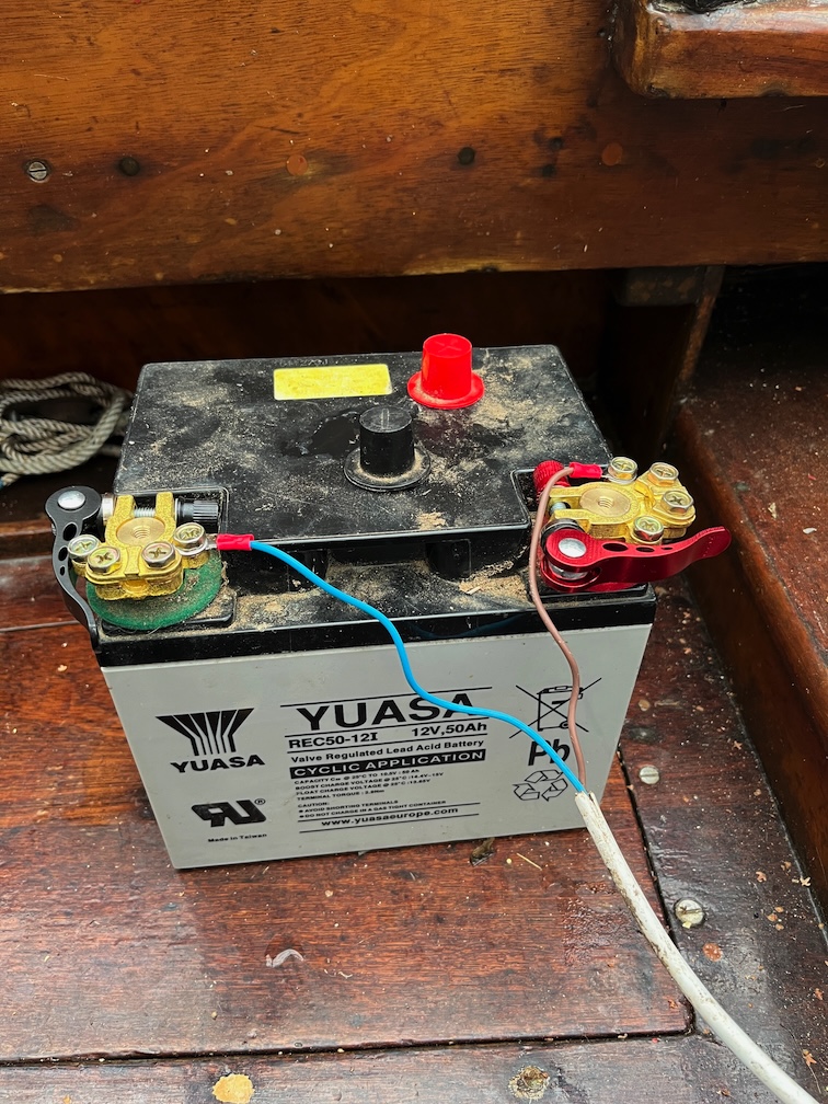
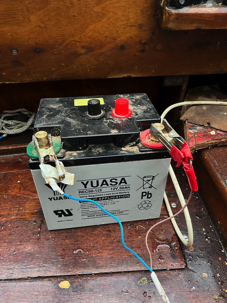
Firstly the battery. Looks much better now even if it is a bit over the top. These things are able to take hundreds of Amps for very brief periods of time and are rated at 100A continuous. I doubt that Shoal Waters will draw more than 10A maximum.
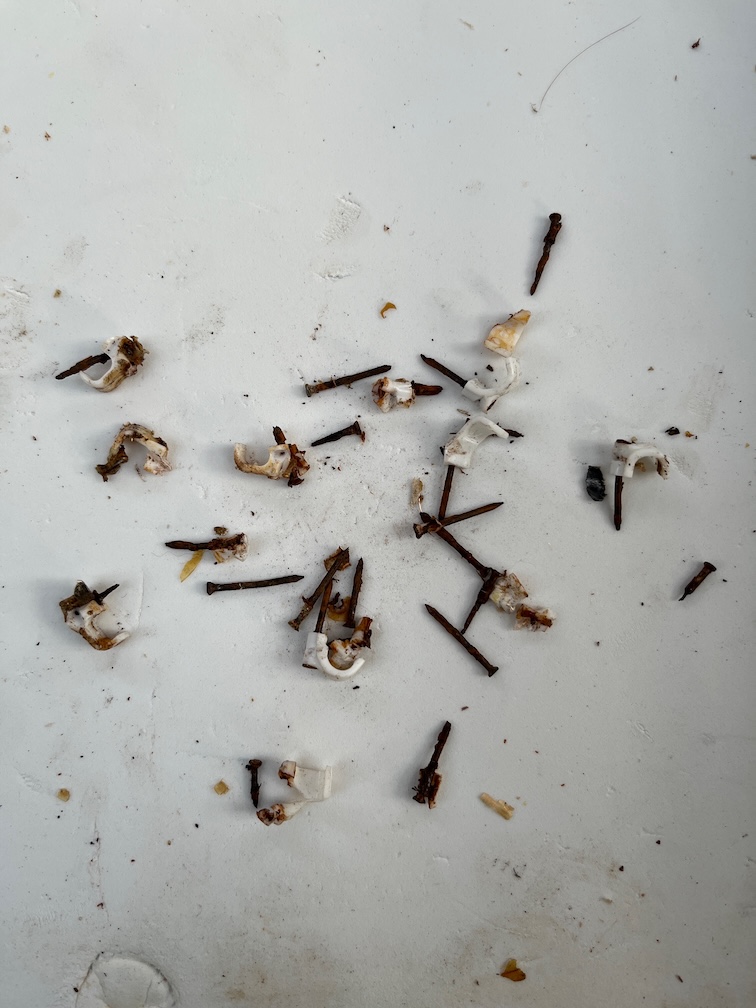
Next up is to secure the cables. Not many clips are required here but they will stop the cables from moving around. I remove the steel pins from the clips and substitute the brass ones instead.
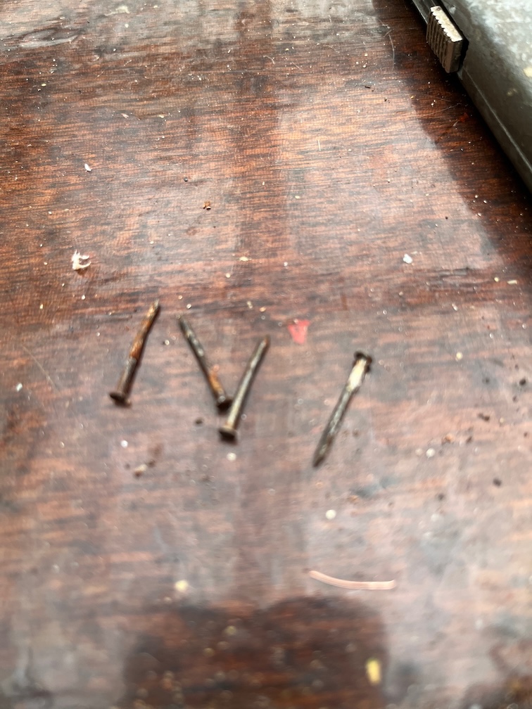
The steel rusts easily, stains the wood and tends to split the clips. Here several clips were removed, damaging the wood a little in the process.
These are some of the steel pins that were taken out. Two are rusted enough to have split the cable clip and the over two just suffered a little surface rust.
Here’s a closer look at the new clip with the brass pin. All of the replacement and new clips will be done this way.
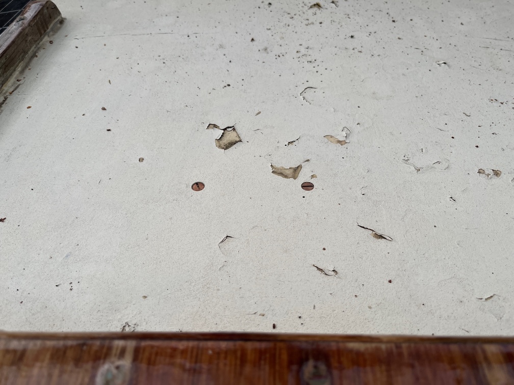
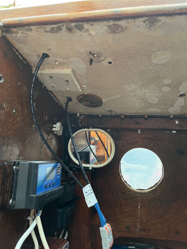
I still had enough light to continue working inside the cabin so I pressed on. The side entry, low-profile deck glands were next. That’s a real mouthful, but accurately describes the items. These are only put in place lightly as paint and epoxy will need to be done before these are screwed down properly, but it keeps the cables neat on the outside and also will allow me to make a couple of bearing blocks that will stop the headsail furling lines from rubbing on the deck glands and the solar panel.
Mind you, this cause a heck of a mess inside. The underside of the cabin top has been lined with polystyrene tiles and then a layer of insulating tiles on top of that. Unfortunately, this all has to come down so that I can inspect the surface of the wood and also to put in the backing blocks for the various screws that will protrude through into the cabin otherwise.
Some of the screws may be seen in the above photo, the black one is temporary but the one that will replace it needs a backing block, even so.
I took the time to sweep up the mess as I’m finished for the day. You can’t really tell from the photo but in the cabin the light is getting a little too dim to allow me to continue working. If the lights were working then it would be a different proposition, but those are next to be installed. Having said that, it’s less than a month to go before the Winter Solstice is upon us and the daylight ours will begin to increase again.
The cabling on the inside has become messy again due to the cables for the solar panel now being on the inside, but with that done and the battery cable sorted out, I can run the battery cable and clip it into place followed by the solar panel cables. Although the panel will be removed and replaced at least once during the refurbishment, the cables will be clipped into place in such a way that they may be removed if required. But that’s a job for another day, possibly tomorrow if it’s light enough in the cabin after I knock off for the day.
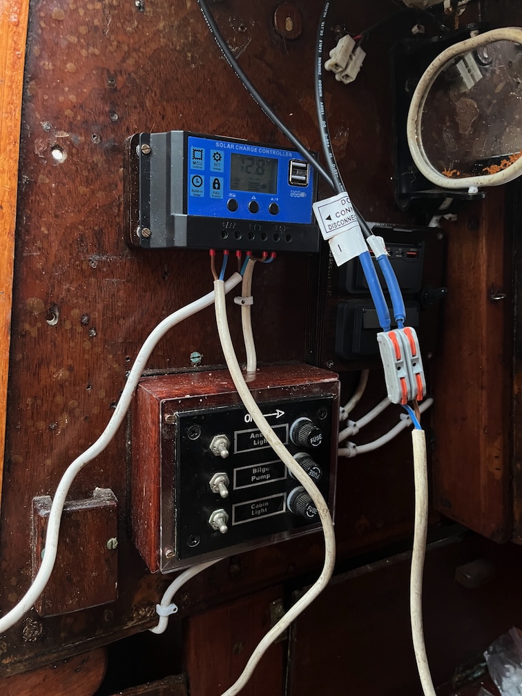
The minimum task I set myself on this cold and wet Saturday was to get the battery hooked up to the controller and the controller wired up to the bus bars in the switch box. Anything after that would be a bonus.
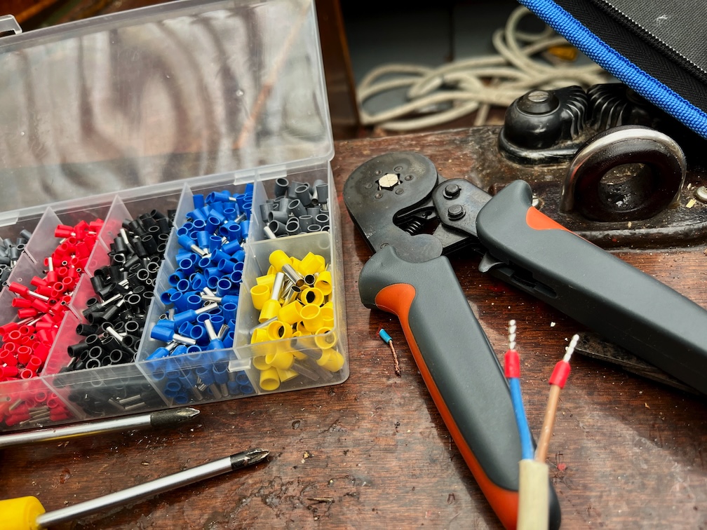
So, starting with the battery cable. I cut off the old ends of the cable, then stripped the individual cores and put on these ferrules using the kit that I bought when constructing my CNC Router.
These fit nicely into the controller connector and I repeated the process with a short length of cable with ferrules on one end and eyes on the other to connect the controller to the bus bars and a similar cable from the bus bars to the USB charging hubs, although this had eyes on the bus bar end and bare, tinned wire at the other to fit into the lever connectors.
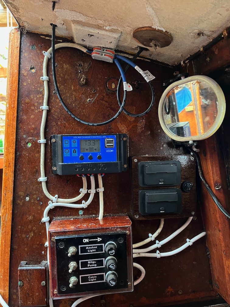
Here is the result with the battery connected. Already past the minimum task and time to break for lunch. As the USB charging hub has a switch built in, the cable from there ran directly to the bus bars as you can see from the photo.
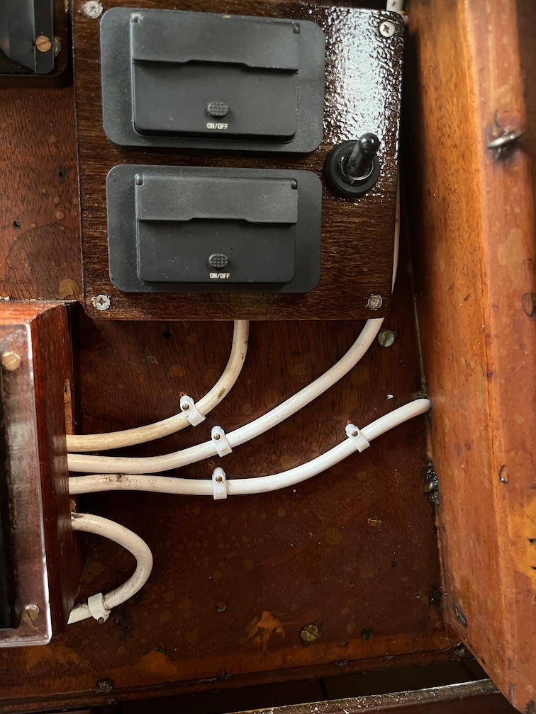
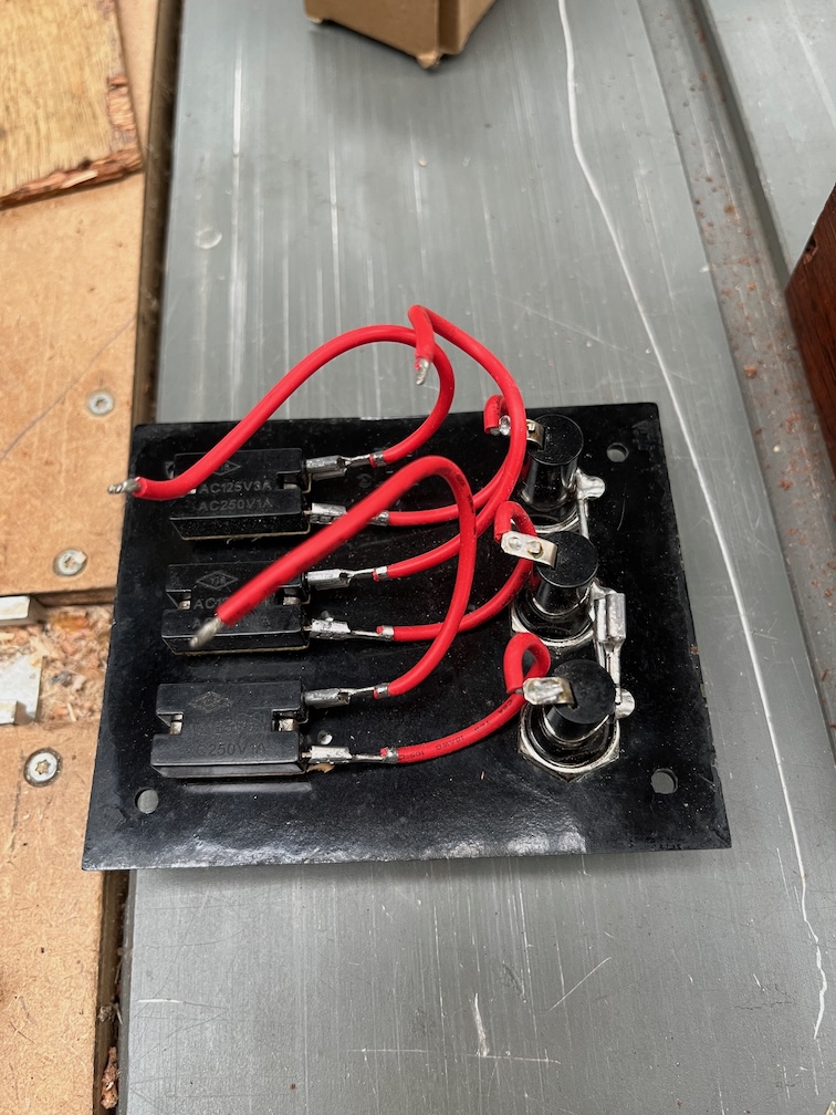
After lunch I turned my attention to the switch box, starting by covering as much of the bare wires on the back of the switch panel with heat-shrink sleeving. Being careful not to get the hot air gun too close to the acrylic panel, of course. For the moment I’ll only be using one of the switches, the one for the navigation lights.
Using a combination of lever connectors, eyes and a spade connector, the cables to the navigation lights were connected to the bus bars and the switch.
This is the result with the switch panel screwed back to the box. Fairly neat and tidy, but I’ll be securing the cables a little better once the cable clips and brass nails arrive, hopefully tomorrow.
So, did it work? Well, two of the three navigation lights turned on when the switch was thrown, the other didn’t have a bulb installed. That was an easy job to fix but even with the bulb in place, the nav light didn’t illuminate. On closer inspection I found that the bulb holder had broken some time in the past and had been glued back together with epoxy. This also meant that the centre pin in the holder that should have connected to the bulb no longer moved and was stuck in the fully retracted position, meaning that it didn’t touch the bulb.
Not to worry, thought I, I’ll just order a new one.
Only I seems that you can’t get them any more, which might explain why the broken one was glued together.
What I need is a brass bulb holder for a BA15S bulb that is threaded on the outside of the body and had screw rings. I can find ones for BA15D and lots for BA22 bulbs, but not for the BA15S.
So, I have ordered the best ones I can find and I’ll figure out how to mount them once they arrive.
Currently, the ship’s battery is out in the cockpit since I need to get into the battery box when replacing the centreplate case and I needed the cable to be long enough to do this. But I must replace those awful crocodile clips! More things to order.
Between some Christmas shopping, making bread and darkness setting in I managed to get in a couple of hours work on the wiring. The task for this afternoon was the (re)installation of the switch boxes and controllers so that the wiring itself may begin.
This involved a lot of getting into and out of the boat and repeated trips to the workshop for various tools, screws and wot-not. I won’t bore you with too many details except to say that I had to juggle the rack on the outside that was screwed on from the inside and the switch boxes and controller that were fixed to the inside but screwed on from the outside. Needless to say, it was important that the various screws didn’t end up under one or other of the items.
This is the result. The new wiring will utilise what I believe are known as lever connectors.
They look like this and I have some inline single connectors as well and for my purposes, they have two main advantages over the normal connector blocks. You don’t need a screwdriver to use them and they don’t rust.
The connector blocks have steel screws to hold the wires and these have a tendency to rust in a marine environment.
The lever blocks do not use screws but a nickle-plated spring on the inside of the connector that is opened by lifting the lever. They can take up to 32A and this is more than sufficient for Shoal Waters.
I will be able to proceed with the wiring and although I’ll be wiring in the solar panel, this will be temporary as the coachroof needs to be dealt with and repainted before the panel is securely fixed in place.
So, the next tasks are to wire in the battery, making sure that there is enough cable to place the battery outside the cabin, wire the controller output to the switchbox, wire in the solar panel and then check that the panel is charging the battery.
Charles Stock had a unique opinion on painting and varnishing that basically said, if it isn’t peeling off, just paint over it.
I have long realised that if paint will not fall off, it is best left on. (A.C.Stock, “In Shoal Waters”, 2013 p31)
This is quite evident in Shoal Waters even to this day. The paint and varnish are thick with many layers and not peeling off.
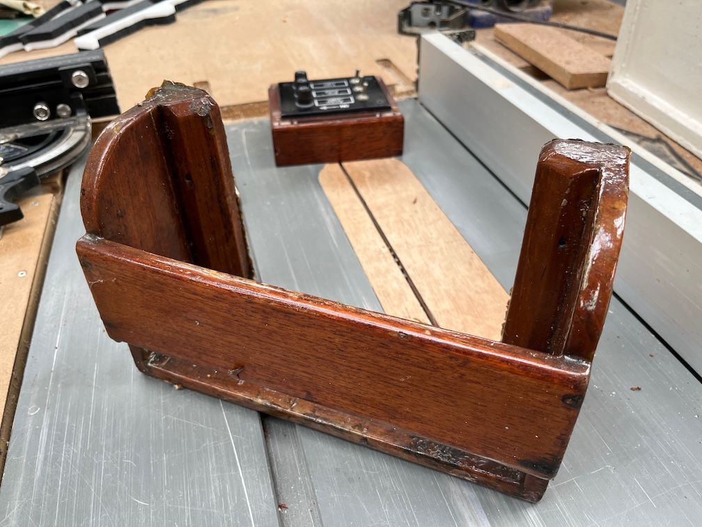
I did find something unexpected about this today. All during the rewiring process I have been meaning to hop into the cockpit and check where the screws protruded, if anywhere, that held the switch box in place. I have changed the way this will be fixed such that the screws are put in from the outside of the upstand and not the inside as before. The problem is that there is a rack on the outside of the upstand that was used to hold a pair of binoculars in easy reach when sailing and I expected this to be in the way of the new screws.
But I wasn’t sure and that required inspection. Unfortunately, I keep on forgetting to do this. I pass Shoal Waters many time a day on the way to the workshop or back to the house and each time I forget.
So this time, instead of saying “I’ll do that the next time I go by the boat” I went out to do it there and then.
I’ve highlighted the rack in the above photo and it’s been there since the boat was built, or shortly after.
Closer inspection showed that one of the original screws for the switch box may have screwed into the right hand side of the rack very slightly and the other just poked through the upstand. With the switchbox removed I could see that the rack was partially loose and I took it off so that it doesn’t get in the way or damaged when fitting the new switch box.
Here it is removed and on the saw table.
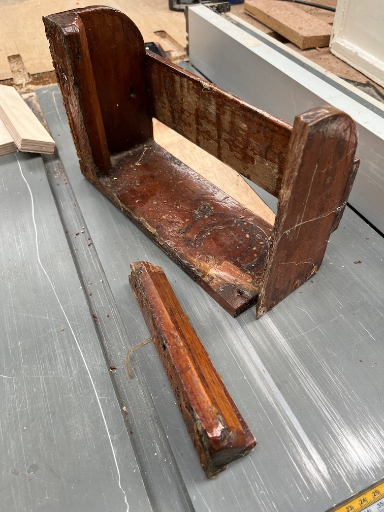
Unfortunately, it broke whilst being removed and this is where Charles’ multiple layers of varnish come in. You see, there’s nothing holding the rack to the upstand except dried varnish. There are holes for screws to be put in from the inside, but no screws. Just varnish.
Looking more closely at the broken section you can see that most of the break is darker in colour than the rest. This is varnish that has seeped into the crack and the lighter bit at the left hand side of the photo is the new break. You can also see two small holes in the edge which will be explained in a moment.
The other part of the rack shows the varnish a little more clearly.
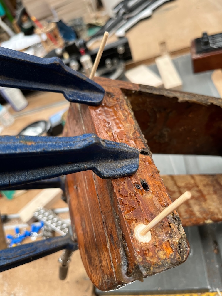
I sanded the break, drilled two holes for bamboo pins and glued the pieces back together. The reason for the bamboo pins is that I don’t have sufficiently long screws of either bronze or stainless steel that are M3 in size and I’m not about to buy some when the pins will do the job. I’m also not going to put in steel screws, which I do have of sufficient dimensions, as these will eventually rust and split the rack apart.
This photos also shows the thick layer of varnish on the wood that is against the upstand. The crack has obviously been there for a while, but I have no idea when the screws were removed. I would presume that they were removed at some point for some reason and because the rack didn’t fall off due to the varnish glueing it to the upstand, they were forgotten about and never put back in.
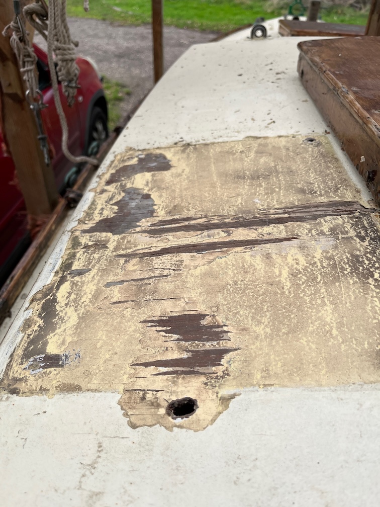
Whilst I was in the cockpit I took a look at the cabin top. I had scraped off all the loose paint that I found under the old solar panel last night but it was close to being fully dark at the time so I was unable to take a photo. Here the wood has had a chance to dry and although there is some slight damage to the surface, there is no rot. Good news here.
I’ll take a sander to it later on and apply a thin coat of epoxy to the exposed wood to strengthen it before painting it again.
While I wait for the spacers for the charge controller and switch box to be varnished, I can work on the front panel of the switch box.
With the walls of the box now much thinner, the existing front panel is too small to fit the new hole. The obvious answer to this is to make an auxiliary front panel to fit the gap. Armed with the box, switch panel, calibers and a CAD program I designed said front panel that I initially cut out of 3mm plywood on the laser cutter.
This is the result. It took four tries to get it exactly correct but that is what prototyping is for.
The new panel will be bolted to the switch panel and screwed to the box. Once I was certain the dimensions were correct I cut the final version from 3mm acrylic sheet.
This came out well and looks very professional. The advantage of having the right tools for the job.
The result is pretty good looking, the black bolts merge into the black of the switch panel and the acrylic allows the wood to show through. The drawback is that you have to remember that the bronze screws are the ones to undo when opening the panel, not the black ones.
Not that the black ones will unscrew since they are bolts with self-locking nuts on the inside. Any attempt to open the panel using those will just result in the bolt endlessly turning.
One of the things I will do before fitting the switch box to the upstand is to cover the exposed connections with heat-shrink sleeving so that none of the connections may be accidentally connected to another wire, such as dropping a screw in the box, although I hope that I’d remember to disconnect the battery before doing anything like that, but I could see a reason to do this if I were using a multimeter to check the voltages on the wires.
The heat shrink sleeving could be considered to be excessive, but I just do not like seeing all those exposed connections. A job for tomorrow, I think.
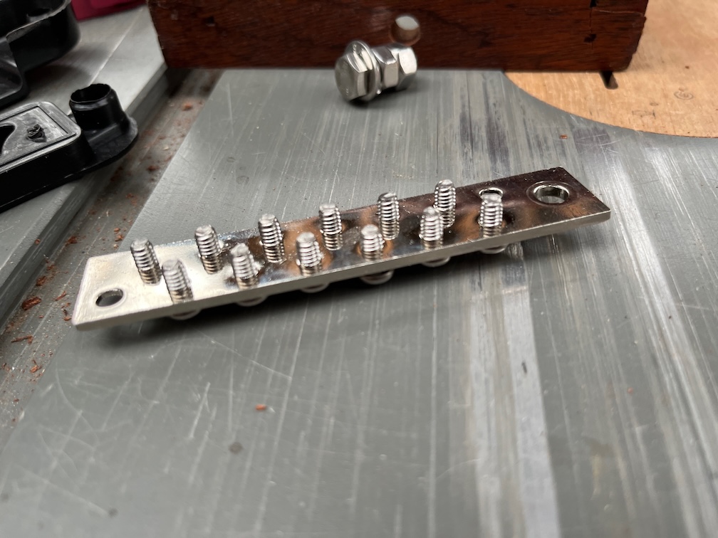
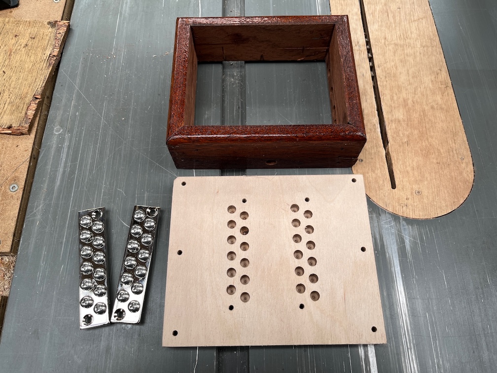
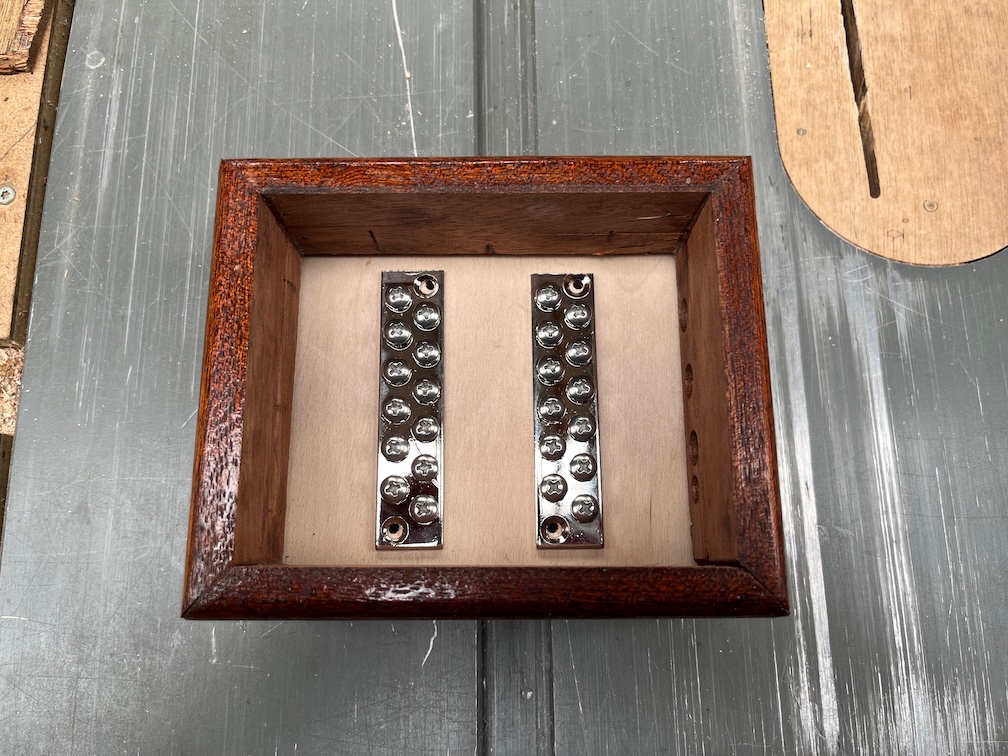
The bus bars arrived late afternoon yesterday and to my dismay, they are not the correct size. I bought this pair of bars to fit inside the in the switch box.
These are the dimensions and you can clearly see that the overall width of the bars is 105mm.
Now the width of the space in the box is 110mm so the bar should fit, but as you can see, it does not. Each bus bar is, in fact, over 140mm long. Looking at the catalogue again I found that the 105mm is the length of one of the smaller bus bars and the given drawing is incorrect.
However, if I remove the metal bus bar from the plastic housing, it is now small enough to fit.
The bolts on the bars extend about 5mm below the bar itself and if I were to mount this inside the box as it is, then there would be a significant problem.
Some of the wiring on the front panel extends into the box quite a distance and even with the connections bend over as much as I can make them without breaking them, they would touch the bus bar and that would cause a short. Not a good idea.
So I spend last night designing and part of this morning making a back plate for the box. It is 15mm thick and has recessed holes for the bolt protrusions. This will mean that the bus bars will be unable to touch any of the current wiring. I may even have space to put in a cover for each bar to prevent anything untoward happening.
The drawback is that the switch box is now 15mm taller than it was before and will be another 3mm taller still once the front plate is made. More on that later. Still, I feel that this is a small price to pay for having proper, protected electrical connections.
Each bus bar can hold 12 connections and so far I have the following for the negative lead:
Port nav light
Starboard nav light
Stern light
Compass light
Cabin lights
USB charging hubs
And these for the positive lead:
Compass light
Fuse bank
Cabin lights
USB charging hubs
I don’t plan to have any other connections, but having a few spare is always a good idea. I may want to run a power lead for a radio, for example. Not a marine radio, a domestic one for listening to things like the Met Office Forecast.
The back plate has been stained with two coats of a dark stain, like the charge connector back plate, and one coat of varnish has been applied. Both the back plates are made from Baltic Birch plywood which is a high quality plywood, but not intended for exterior use without treatment as the glue holding the veneers together is not waterproof.
The stain is to darken the very light colour of the wood and the varnish is to protect the wood from any damp. I expect to apply around four coats to all the surfaces, then lightly sand the visible edges and give them another two coats. After that, they may be fitted into the cabin, although not the final fitting, and the wiring adjusted to fit the new arrangement.
It is, however, November (already) and staining and varnishing in the workshop is a long process due to the extended drying time. So, I’ve been staining in the workshop and bringing the pieces into the kitchen where they are placed on the Rayburn to dry. Once the staining was completed, both pieces were taken into the workroom where the varnishing is done. Here the procedure is to apply a coat of varnish all round, using screws as standoffs and once the varnish has cured a little, the work pieces are returned to the Rayburn to complete the curing. Even so, it is a laborious process especially since the next part, adjusting the wiring, cannot be carried out without the controller and switch box mounted.
Oh well. That’s boat building for you.
Once the wiring from the controller to the switch box, the other wiring and the battery cable to the controller are done, I’ll mount the new solar panel and route the wiring to the controller. Again, this will not be the final fitting as there is still a bit of work to be done filling holes and repainting to done to the cabin top, but that will be enough to verify that the new wiring layout works.
I elected to make a start on the rewiring of Shoal Waters since I will be needing a light in the cabin in the evenings and that seemed to be a good enough reason to start on the electrics. Now I have to say that I had wondered about the comments that the surveyor made about the electrics, and I quote:
The wiring loom is untidy, poorly routed and loosely cable-tied.
I couldn’t see what he meant by this. The cables in the cabin were neatly run and held in place by cable clips even where the cables ran under the bridge deck and not in view.
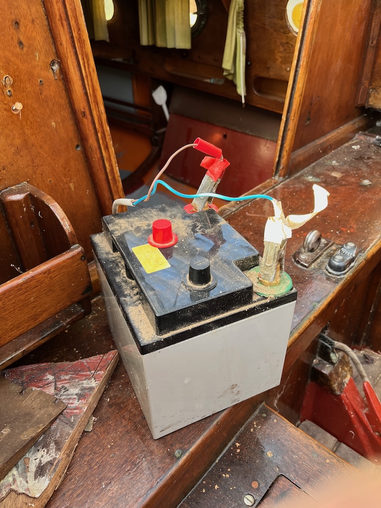
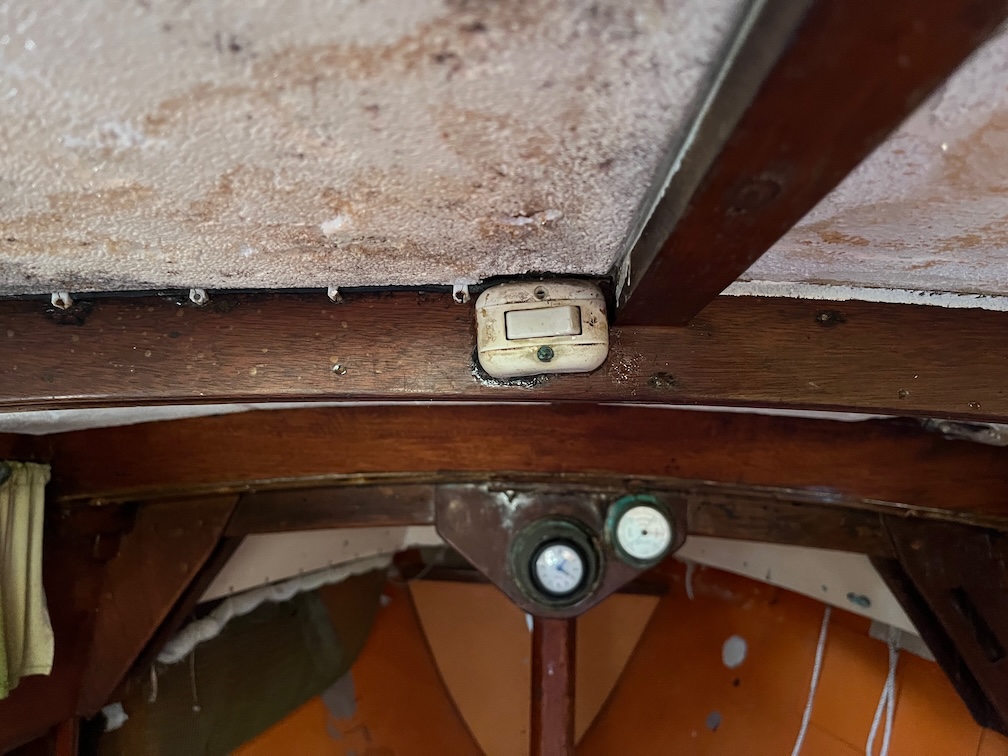
Then I looked in the battery compartment and then it became clear. I forgot to take a photo of this, so I’ll try to describe it. Originally, a single cable ran from the battery to the switch box
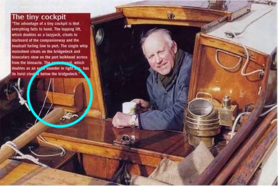
You can see the switch box in this photo just above the radiant heater. Now, the battery cable was attached to the battery with large crocodile clips. All the services ran from the switch box. The cables to the nav lights, including the stern light, and the original cabin light you can see above the switch box. The switch for this light is mounted to the underside of the cabin roof just forward of the hatch making it easy to turn on when opening the hatch in the dark or when sitting in the cockpit. No fiddling around trying to work out which switch was the correct one on the switch box.
Some time later, Charles added a small 5W solar panel to keep the battery charged and the cables for this were neatly run with cable clips into the battery box. This cable also ended with large crocodile clips and these were clipped to the first set of clips on the battery.
Later still, a three-port 12v lighter socket bank was added and this had large crocodile clips that were then clipped to the ones for the solar panel. The excess cable was wound around one of the other cables to keep it out of the way.
So, the battery locker had three sets of large crocodile clips stacked one on top of the other and the cables fixed together with cable ties to prevent them from getting tangled up and pulling the clips loose.
It was a mess. Known in the trade as rat’s or bird’s nest wiring.
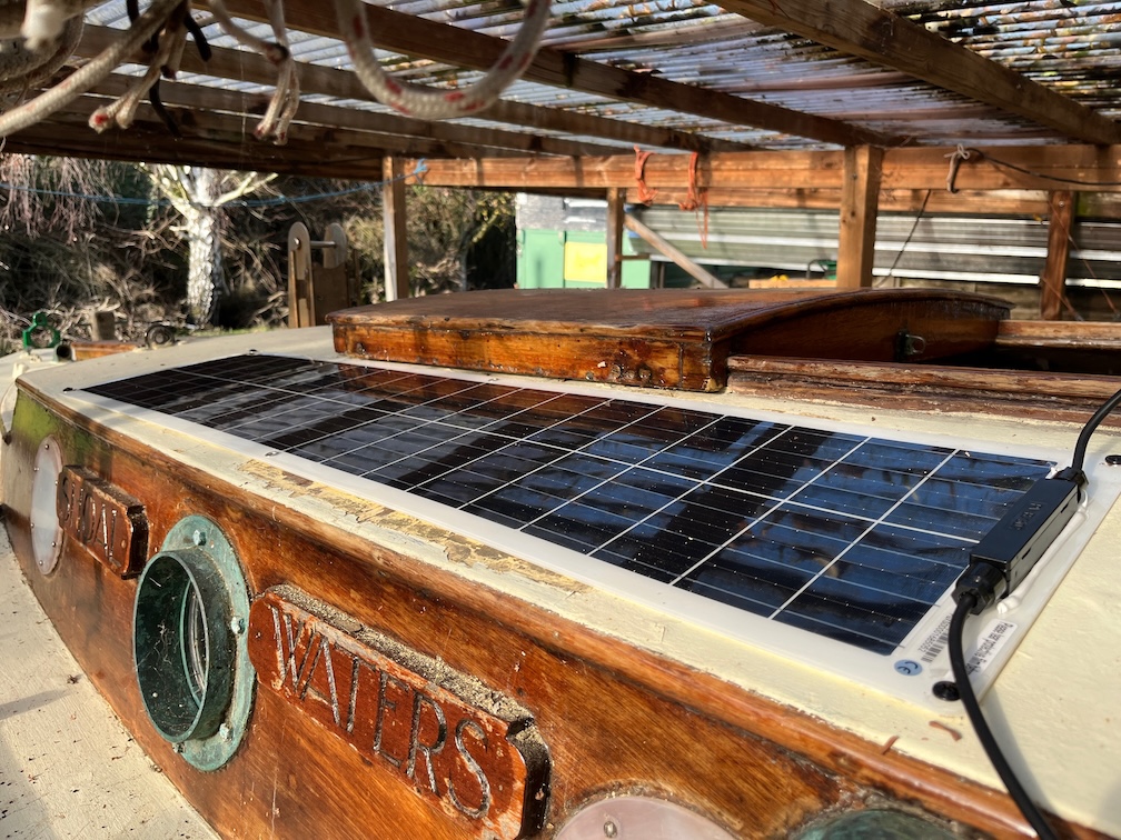
Now, the life of a solar panel is around 10-15 years for one like this and that’s for a modern one. Some of the very latest ones may last 25-30 years but this panel is not that good and is already around 20 years old. The surface is yellowed and starting to crack and it looks like there has been some water ingress through the bolt and screw holes holding it to the cabin top. So it will be replaced.
Now this is where it gets a little tricky. A 5W panel may have been sufficient when first installed before the days of electronic navigation aids, mobile phones, drones, video camera and so on, but these days it’s just not going to be enough if you spend a few days aboard.
A quick electronics lesson. Every few seconds your phone sends out a signal effectively saying ‘This is me’ and the nearest cell tower picks up this signal and relays that back to the service centre so that when a call is made to your phone, the service knows where the phone is and can send the call to the correct cell tower. So, even when you are not using it, the phone is transmitting and using battery power. If there is a good signal to the tower, then the phone only uses a small amount of power, but if the signal is poor, only one bar for example, then the phone transmits at a higher power to reach the tower. This is why your phone seems to run out of battery power much more quickly when the reception is poor.
The reception in the Blackwater River is poor just about everywhere and so a phone, when aboard, needs recharging more often than when ashore.
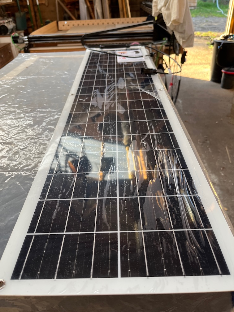
Anyway, I decided on a 50W flexible solar panel since I can get one with that power rating that will fit onto the cabin top.
It looks quite large in the photo, but it will easily fit onto the cabin top where the old one was, just extending a lot further forward.
Here’s the old panel removed and you can see the yellowing of the panel which reduces its efficiency greatly. Also note the crocodile clips.
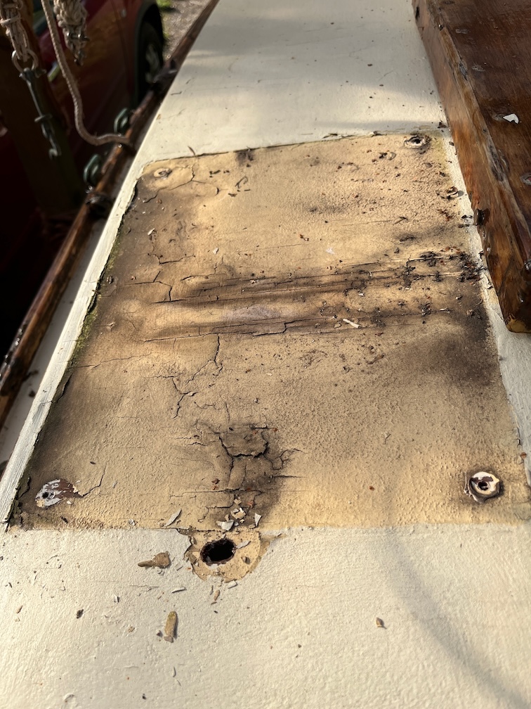
The paint under the panel is old and cracked and I’ll have to check the state of the plywood of the cabin top. There might be some rot or water damage there.
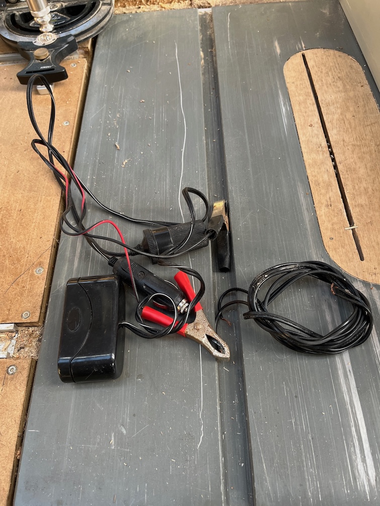
This is the 12V lighter extension cable complete with crocodile clips.
Finally the battery leads again with crocodile clips !! These one will remain, the rest will be ditched.
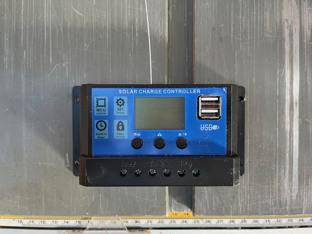
Now, it is inadvisable to attach a 50W solar panel directly to a battery as you run the risk of overcharging the battery, also known as cooking it, and damaging it over time. Instead you should use a charge controller.
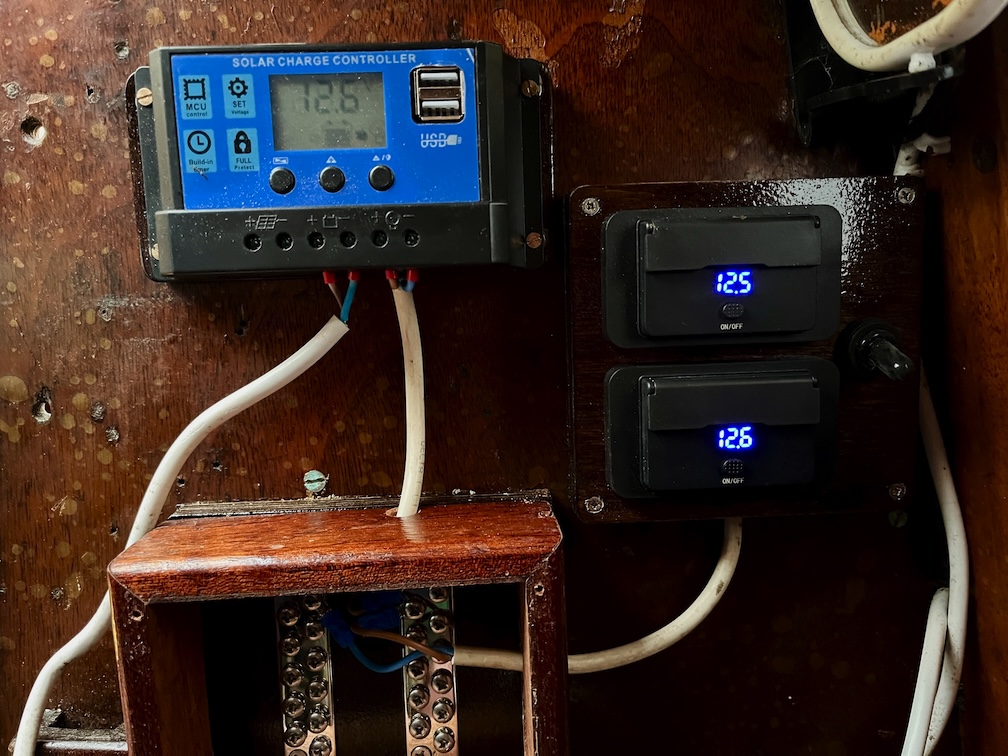
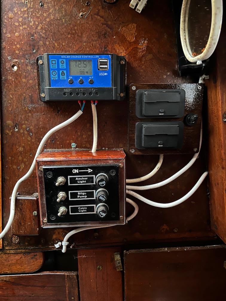
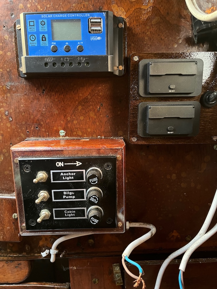
Like this. Not only does this monitor the battery state but prevents the solar panel from overcharging the battery. It also has two USB A sockets for charging devices.
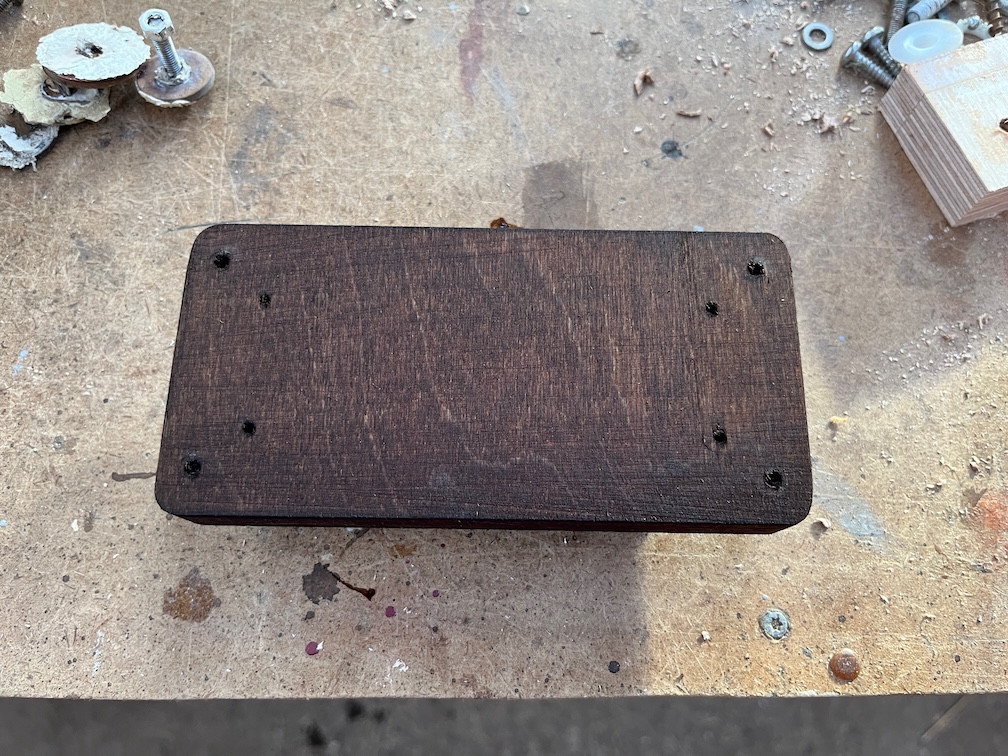
The aft cabin upstand is too thin to screw onto directly, so I’ve made a mounting block. This will be screwed to the inside of the cabin upstand from the outside and allow the charge controller to be screwed to the block on the inside without the points of the screws protruding out anywhere. This is made from Baltic Birch and since it is normally a very light colour I’m staining it before applying varnish to make it fit in with the rest of the cabin.
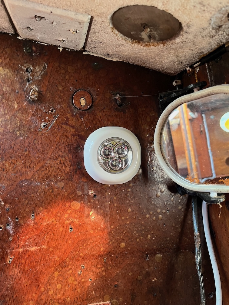
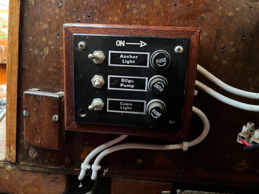
Currently, the lighting in Shoal Waters is very limited.
This is it. Powered by three AAA batteries it is the lighting for the entire interior of the boat. If you want any more than this, you need to use a torch. You press the clear plastic lens in to turn it on and again to turn it off. I don’t like this, at least not for the main lighting, it’s too limited and you have to keep at least three spare AAA batteries to make sure you don’t run out of power. I may well keep it as a backup, but I’ll have to try it out in the dark first to see how well it lights up the cabin.
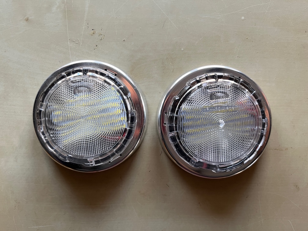
Instead I shall install these. One amidships in line with the galley so that whatever is cooking is illuminated and the other forward of the mast so that you can get to it when in bed. You rotate the plastic lens clockwise to turn the light on and back again for off.
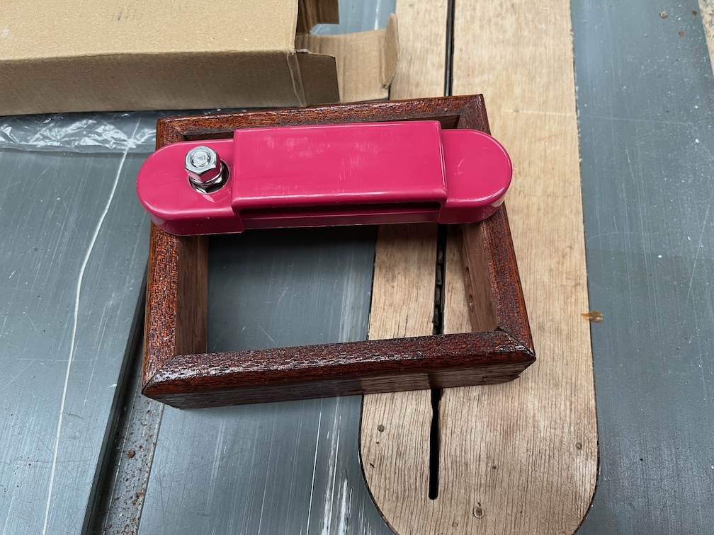
This is the original light switch. I don’t know if it still works, but if it does, I may well use to do turn a red light on and off for night sailing. To be decided. I don’t have a red light but I do have all the parts to make one.
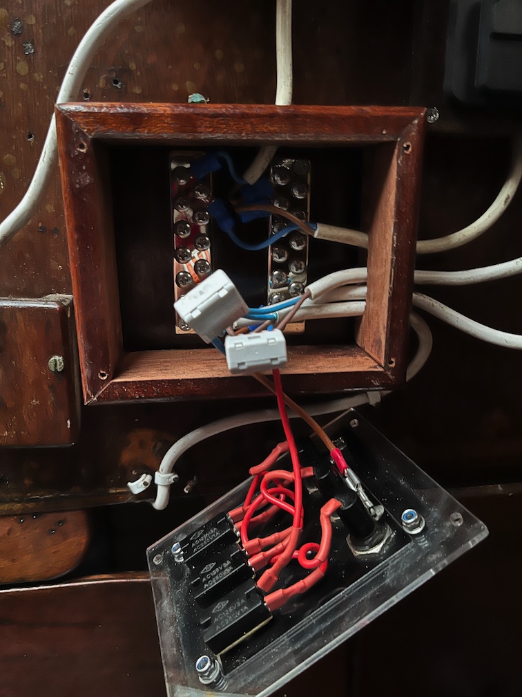
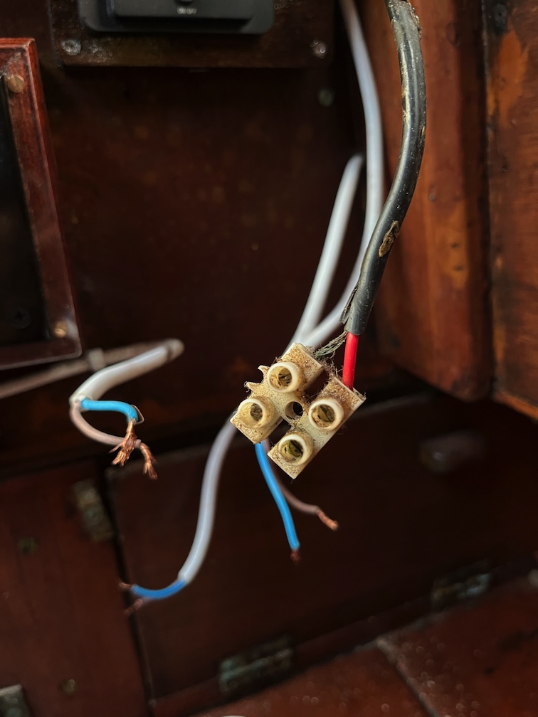
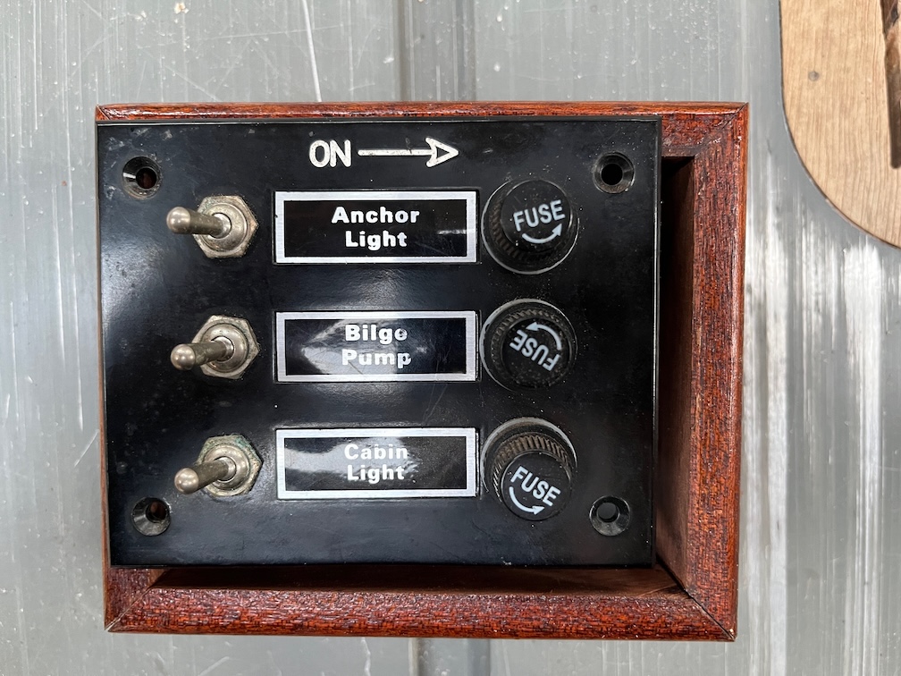
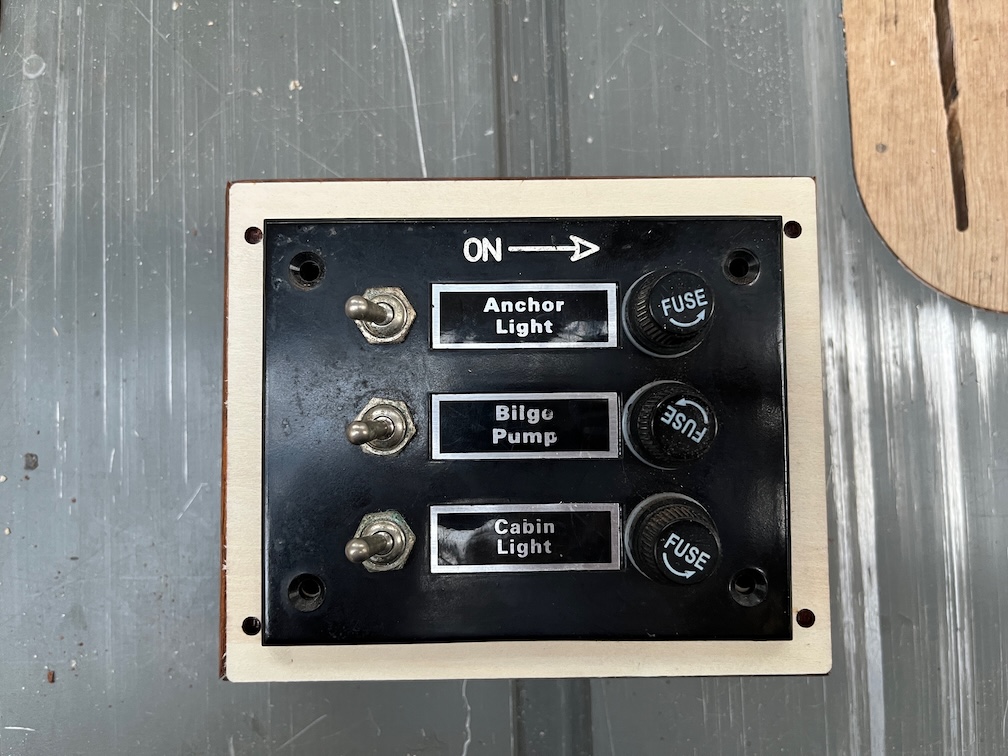
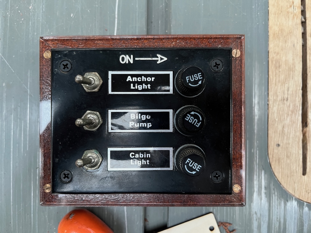
The next thing to look at is the switch box.
Looks quite nice, doesn’t it?
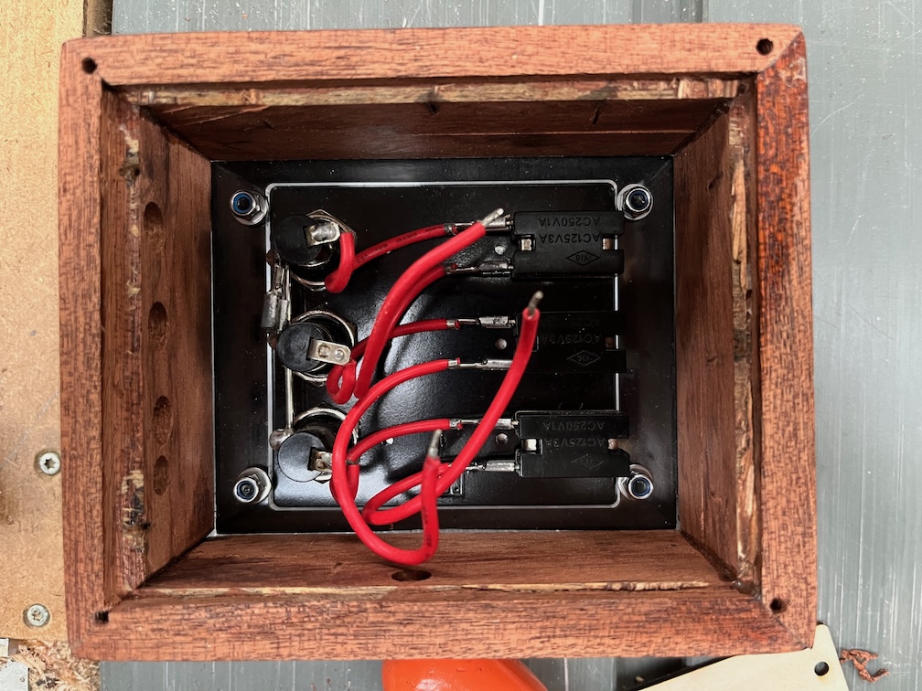
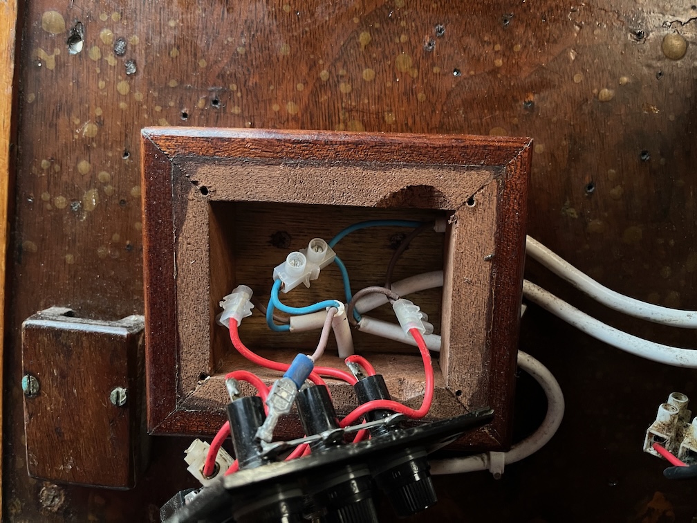
Until you open it up. then, there is a problem. Well, two. Firstly the inner recess is far too small and secondly, it’s a bit of a rat’s nest in there.
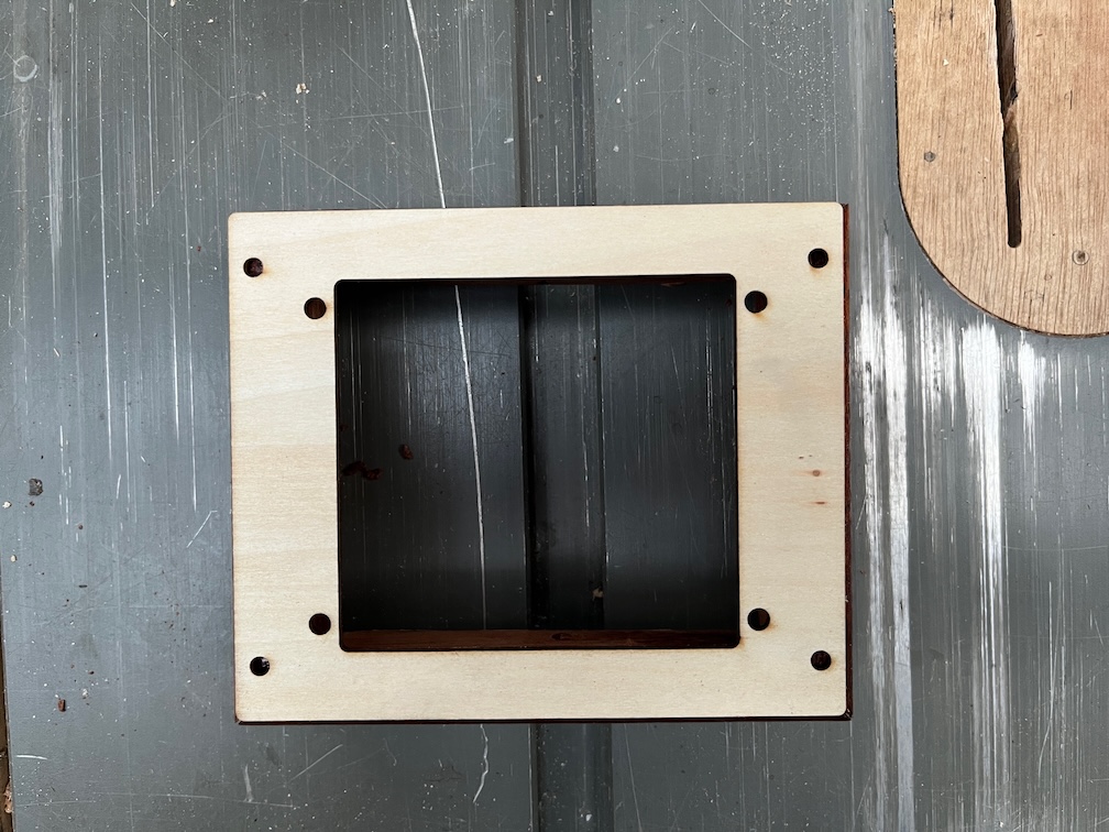
So, I took it out of the boat…
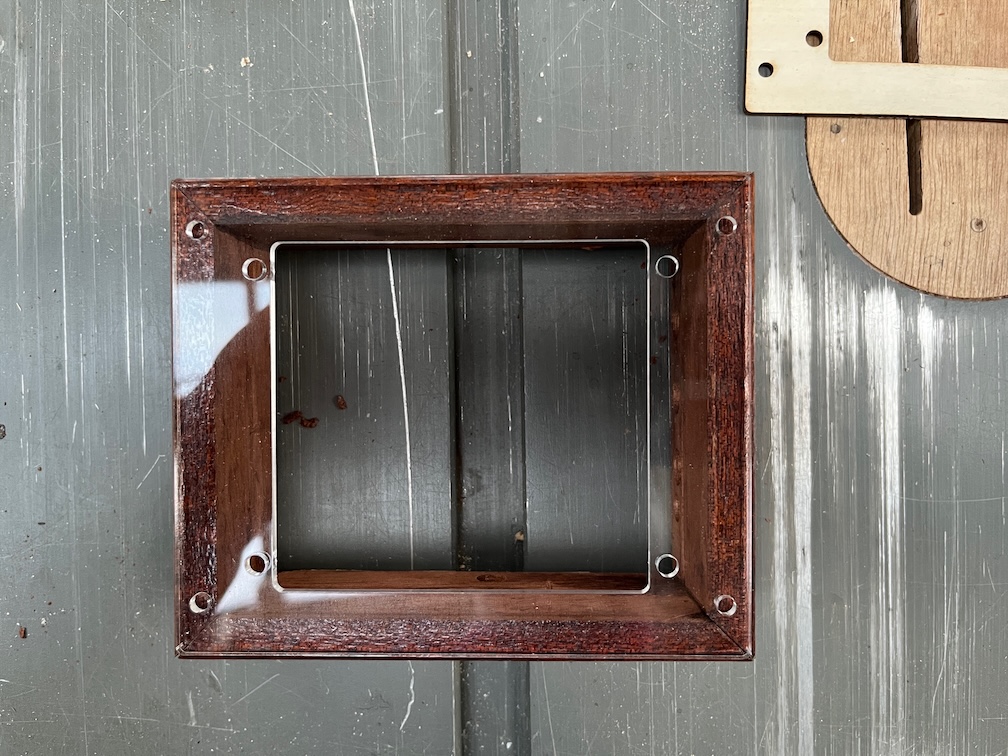
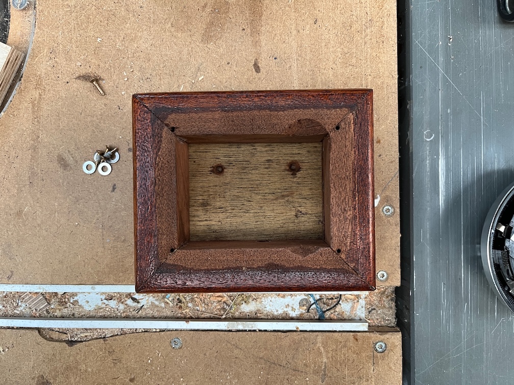
..disassembled it and cut the side walls down so that they are about half the thickness that they were. Now, why did I do that? Firstly, with more space inside it will be easier to add or change the wiring. Secondly, I want to put in a busbar for the negative from the battery.
Like this. If I can fit both in I will but the main thing is to get the black one in. That will tidy up the wiring considerably.
So, there’s a lot to be getting on with. I’ve made a good start.