2026-03-03 – Case Top & Rubbing Strake

The first task of the day was the fourth coat of varnish on the new aft navigation light mount and that before breakfast to get it out of the way and done.

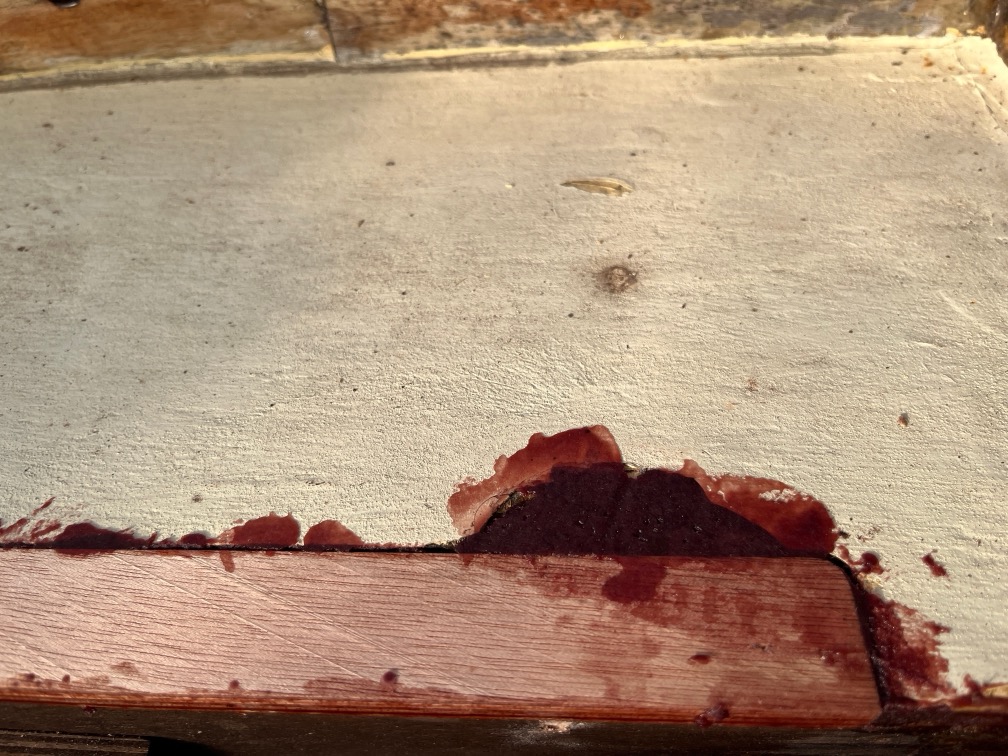
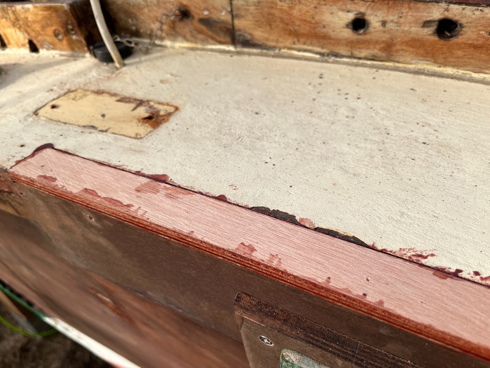
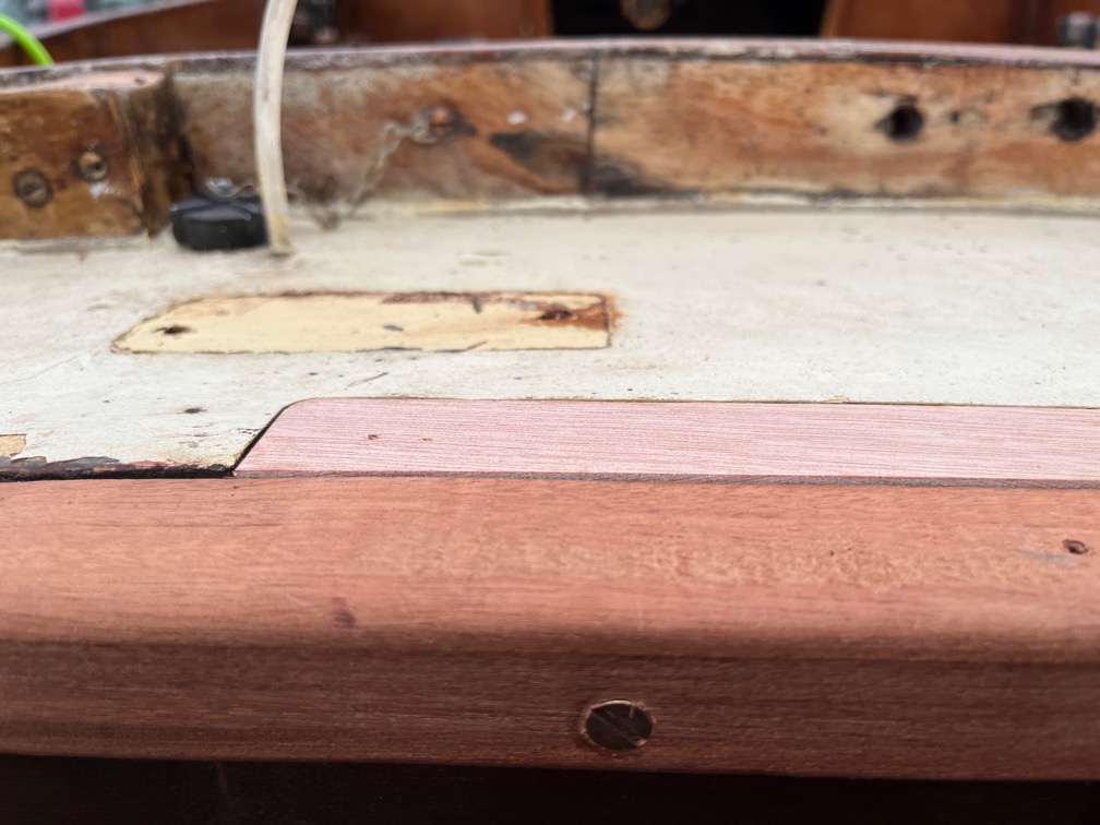
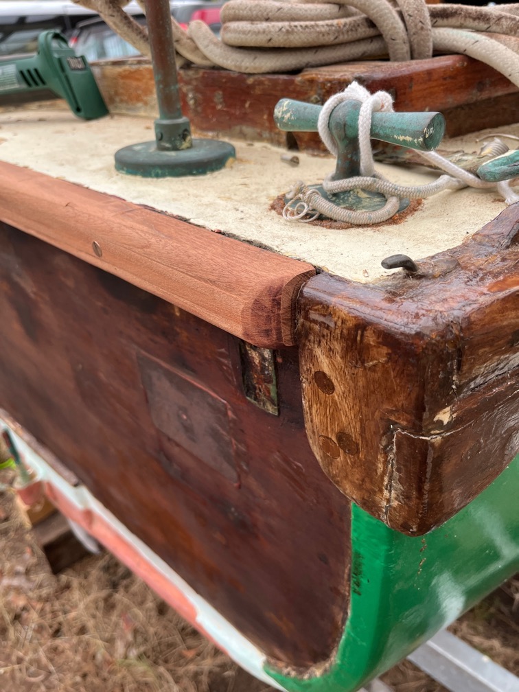
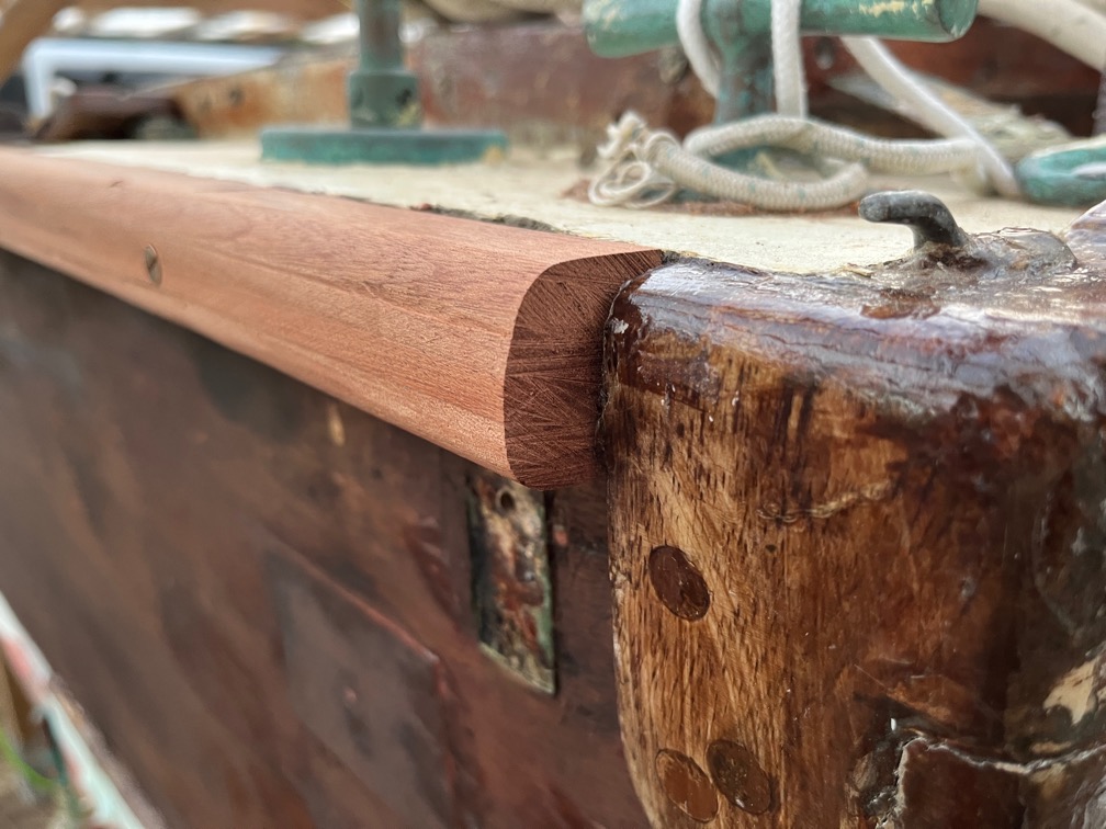
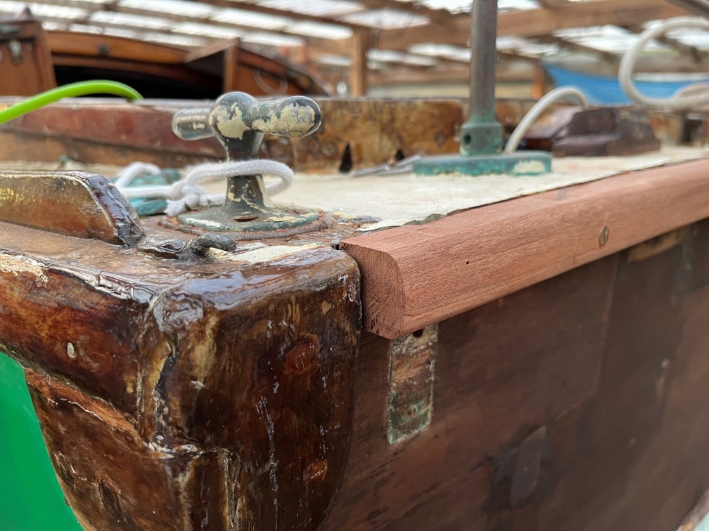
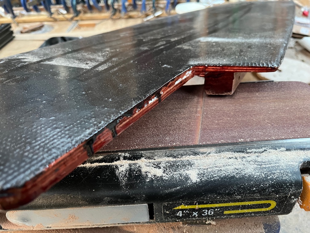
For my first tea break I cut then end of the dowel that was glued in last night, flush with the transom and gave the entire area that will be under the rubbing strake a sand to get rid of any high spots.

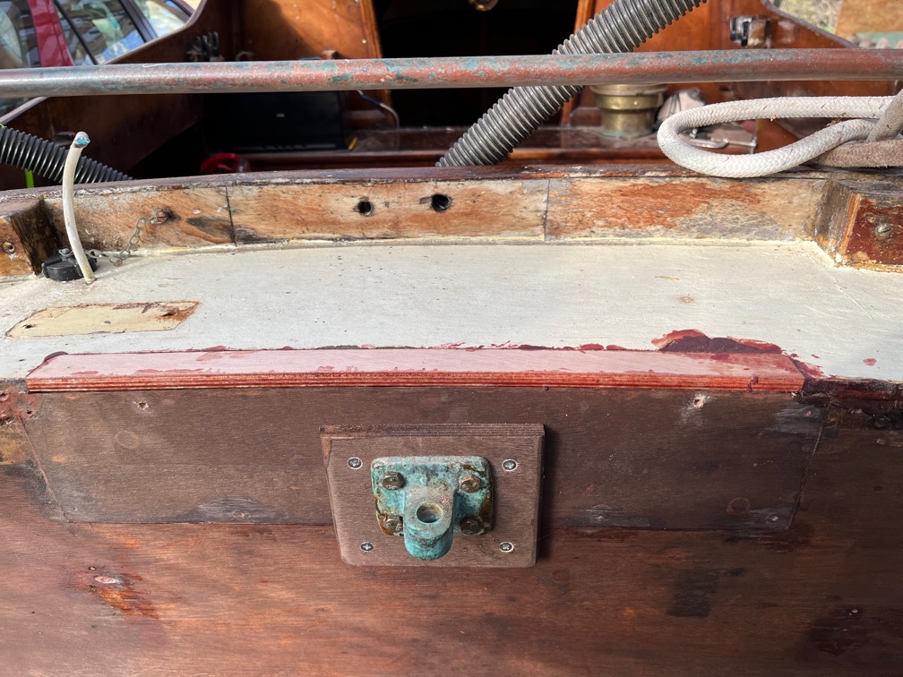
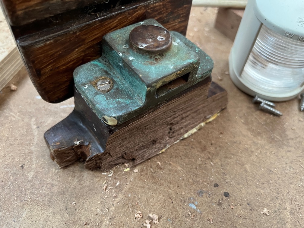
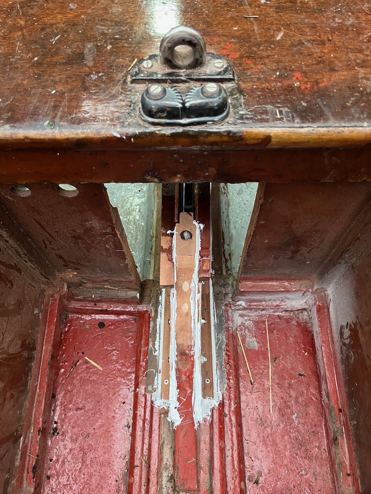
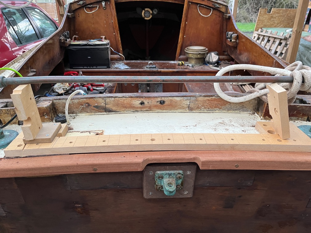
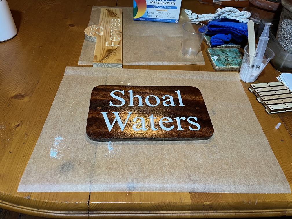
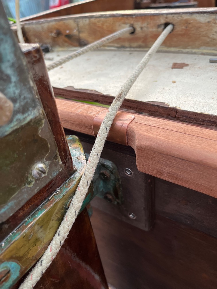
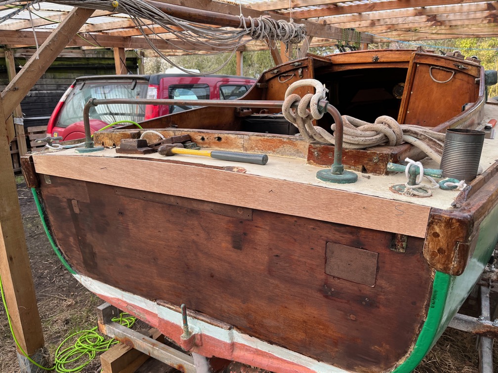
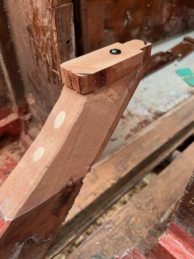
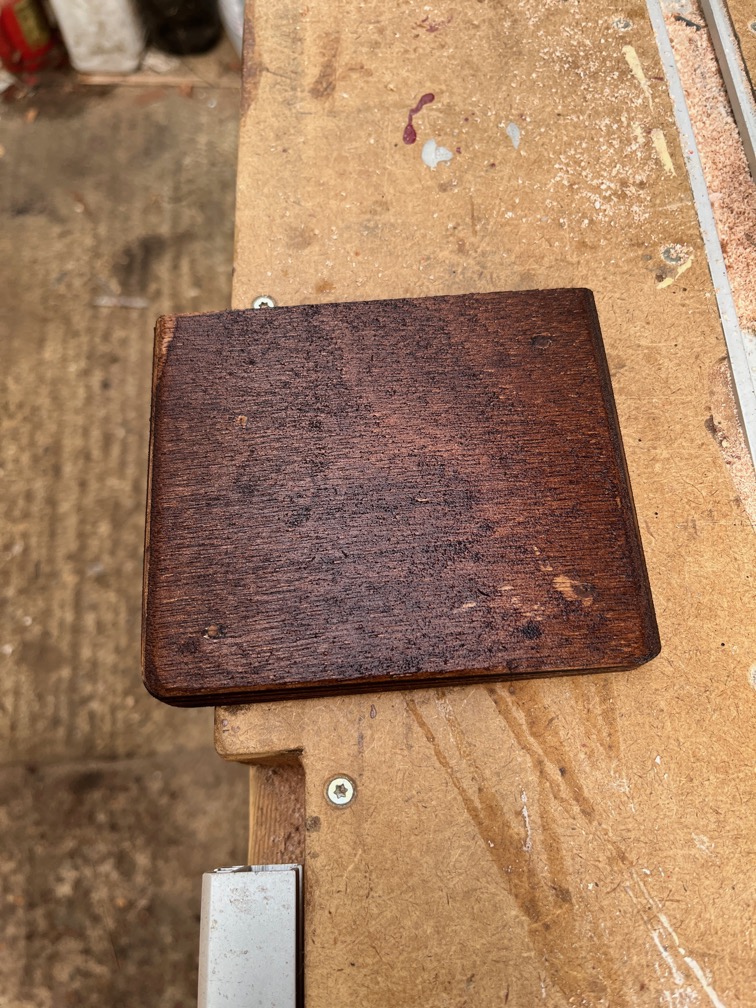
Following that I put some new screw hole in the case top that was on wonky and screwed that down to the case. As you can see, it is no longer wonky. I also gave this a quick sand as it will get a coat or two of varnish in the near future and I had the sandpaper to hand.

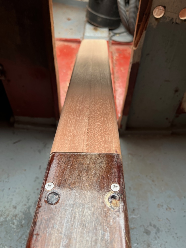
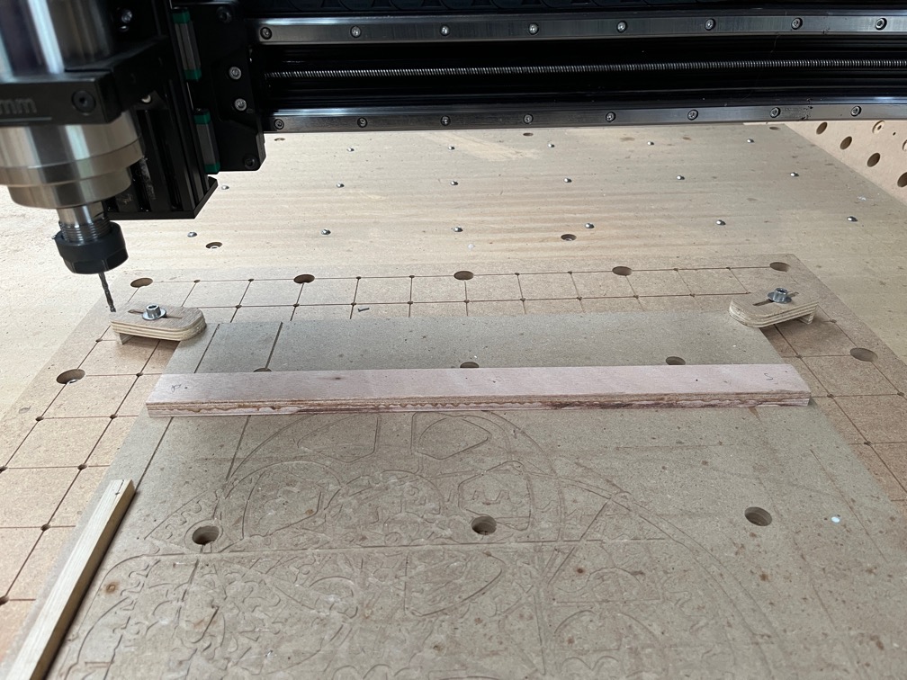
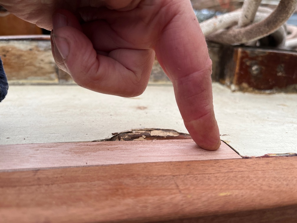
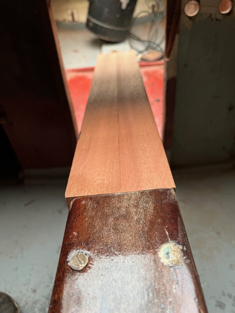
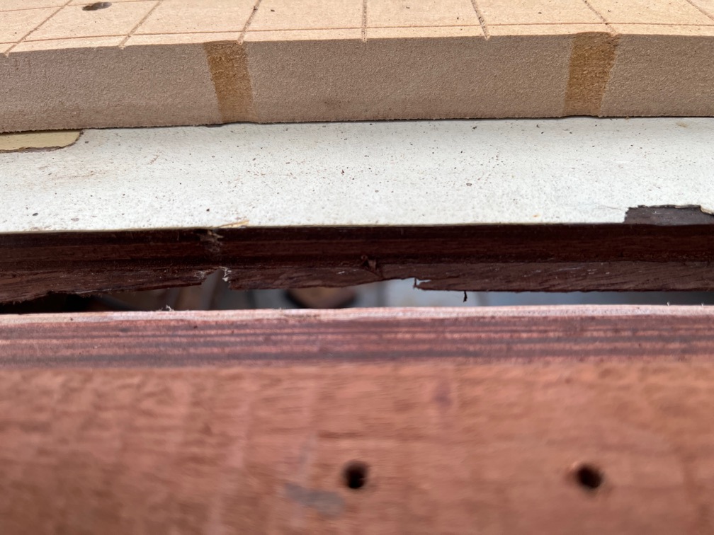
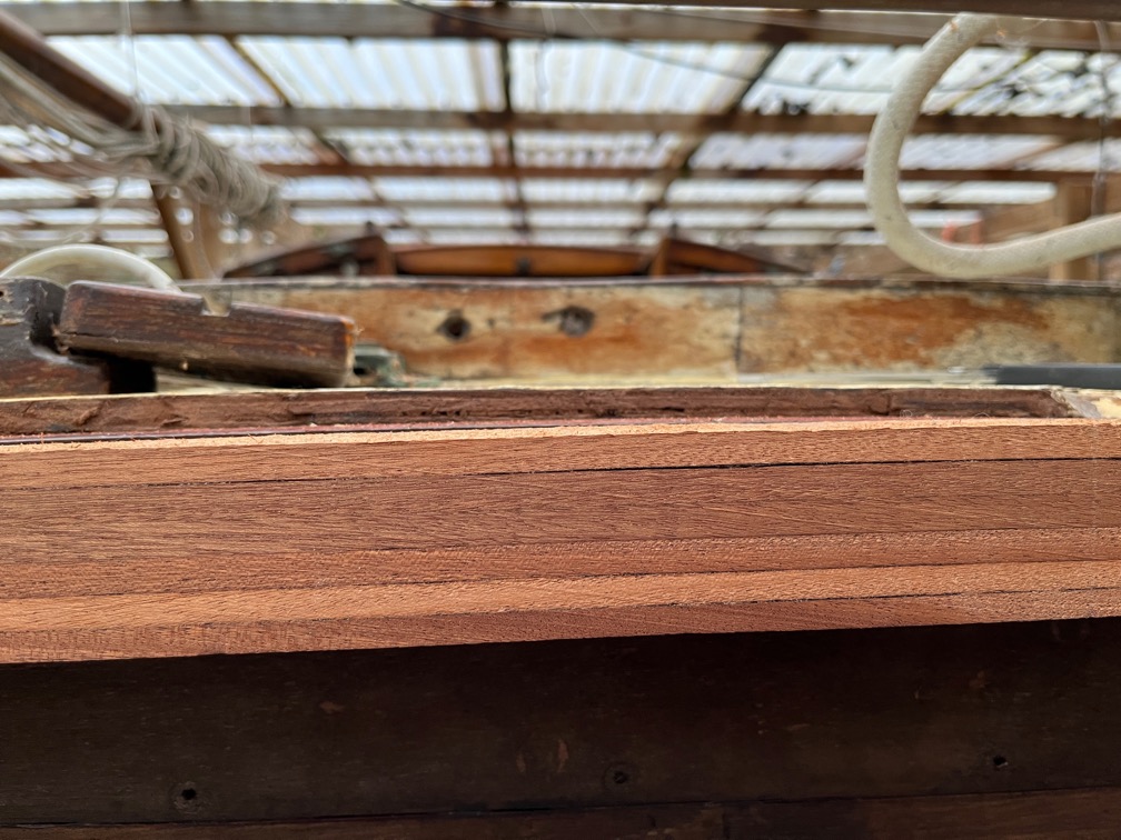
Finally, I checked that the new piece still aligned correctly and marked the cut line at the aft end.

Then it was back to work.

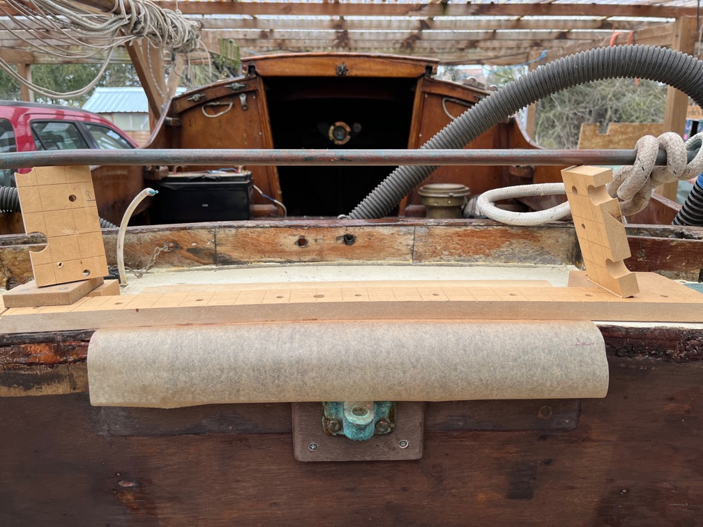
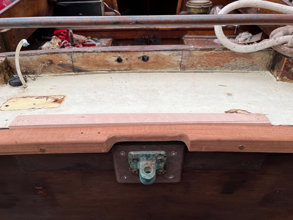
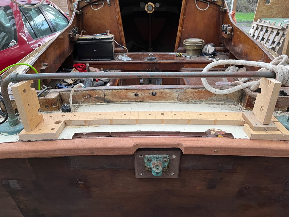
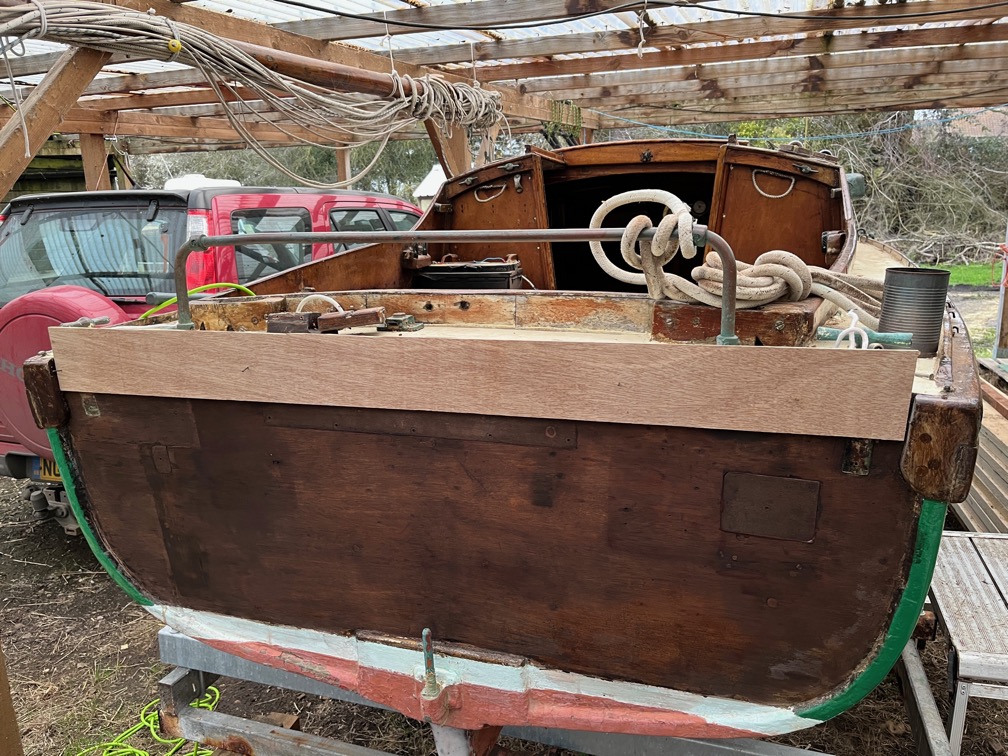
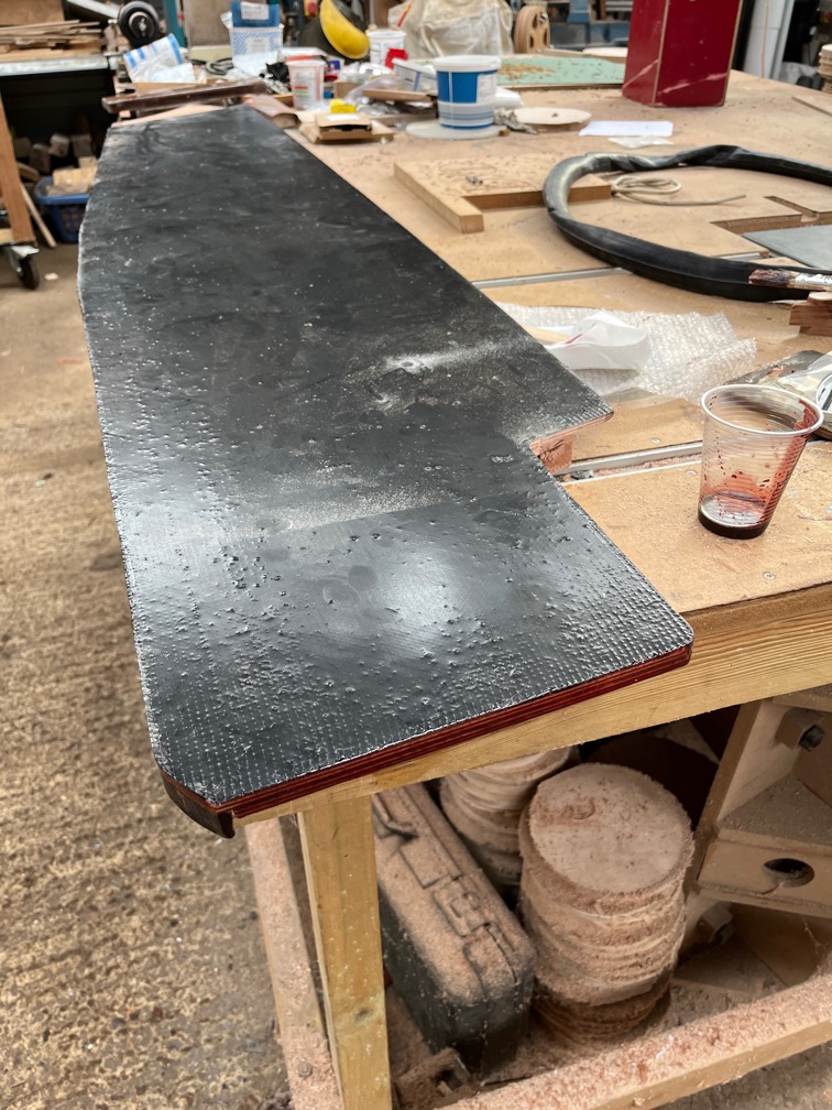
The lunchtime tasks started with putting the screw holes in the new case top and fry fitting it, just to check.

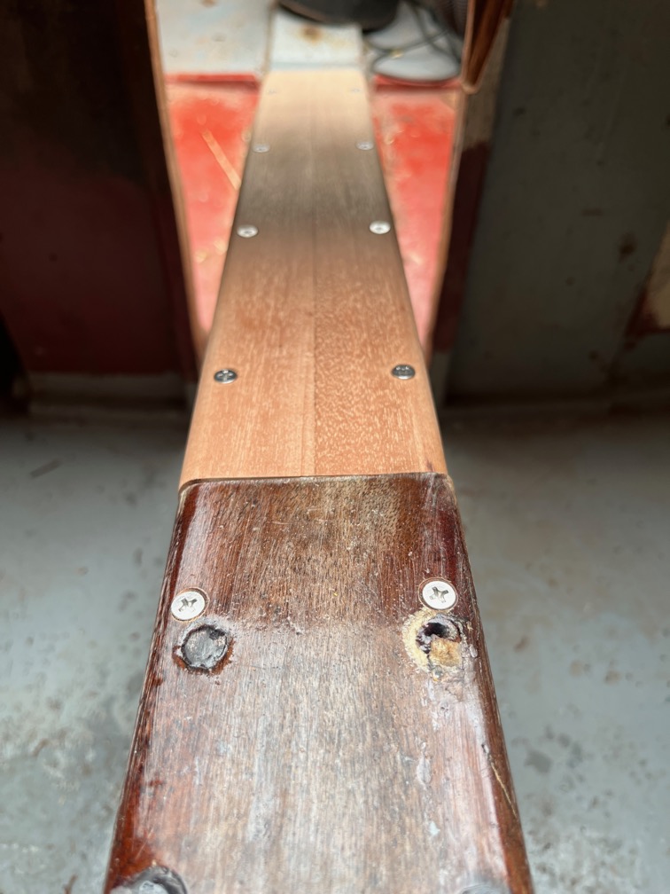
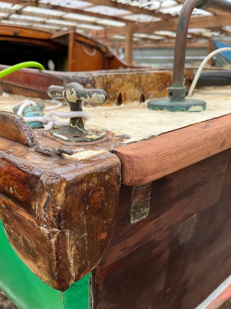
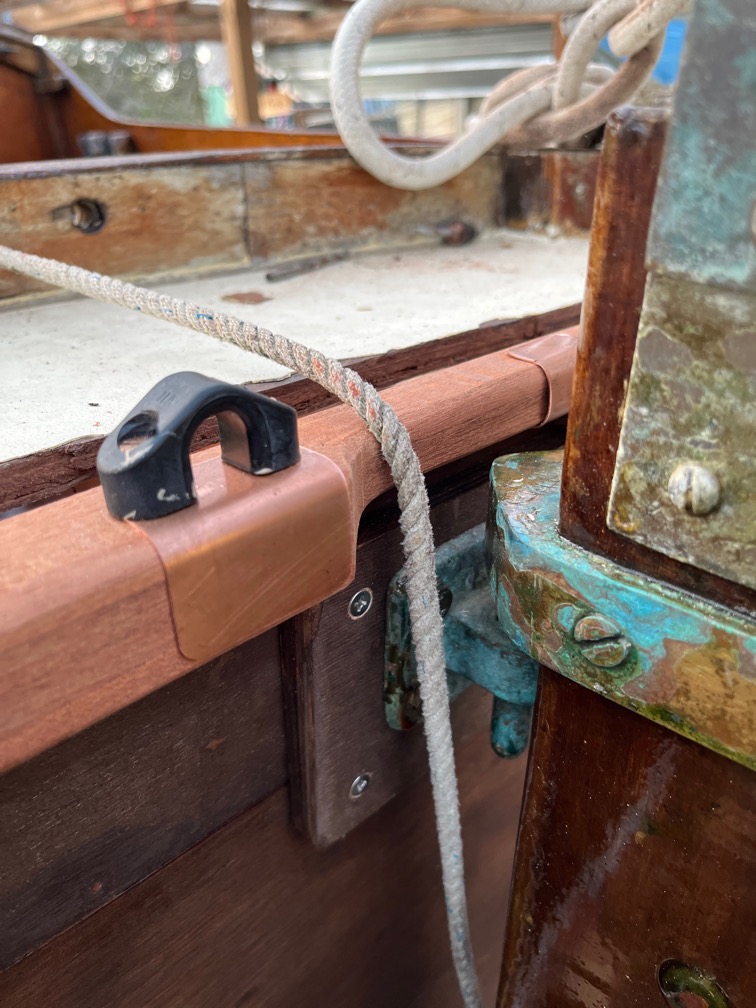
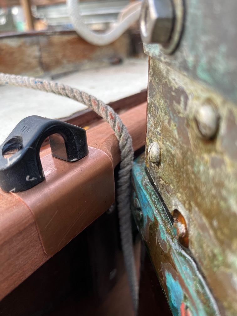
A pretty good fit ad the slight mismatch is due to the rounding on the old piece not being quite the same as the new. Not going to worry about it, though.

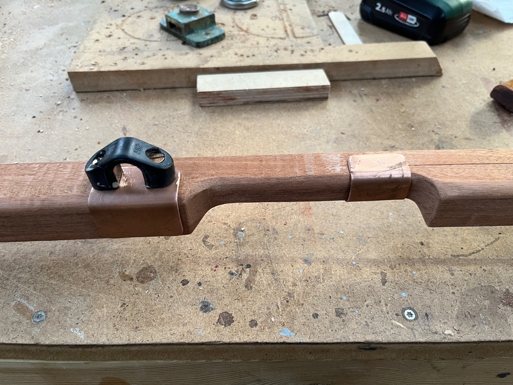
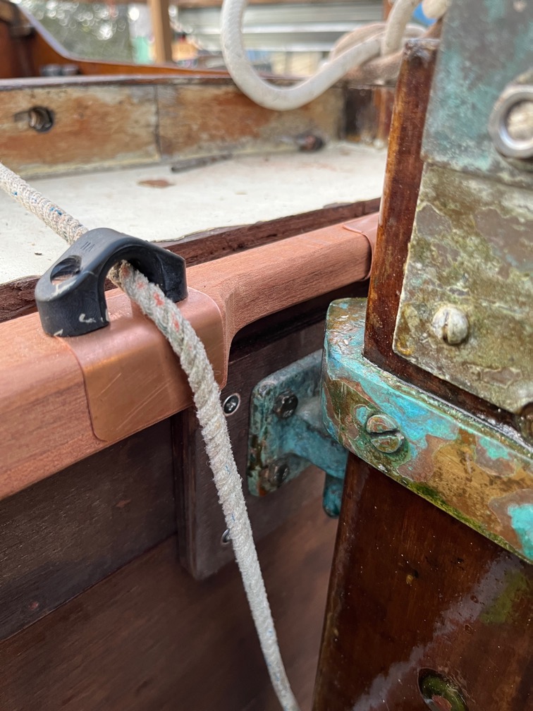
At the other end the fit is good and there is plenty of space to mount the plate uphaul jamming cleat.

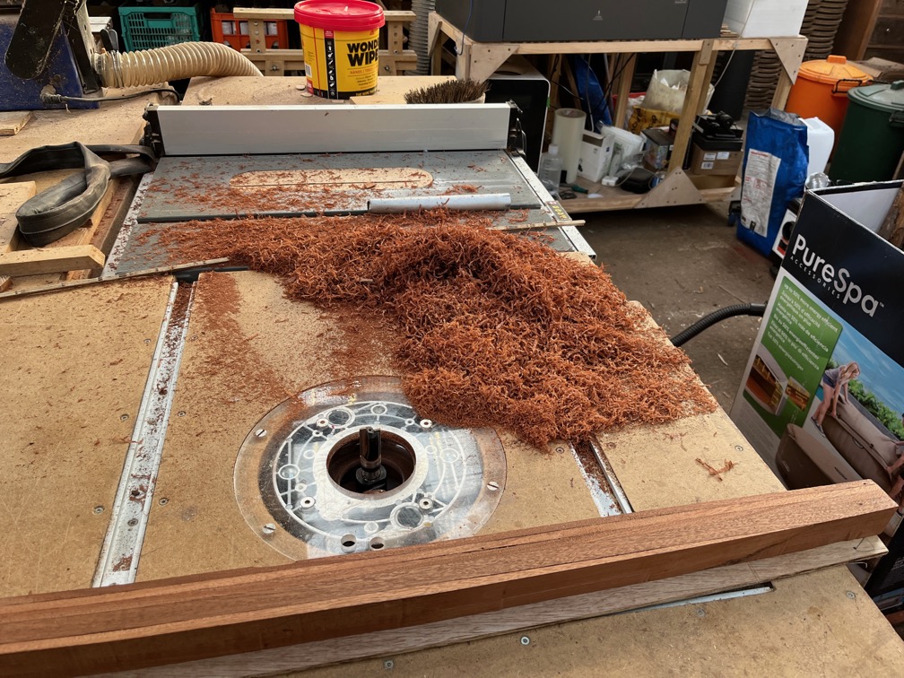
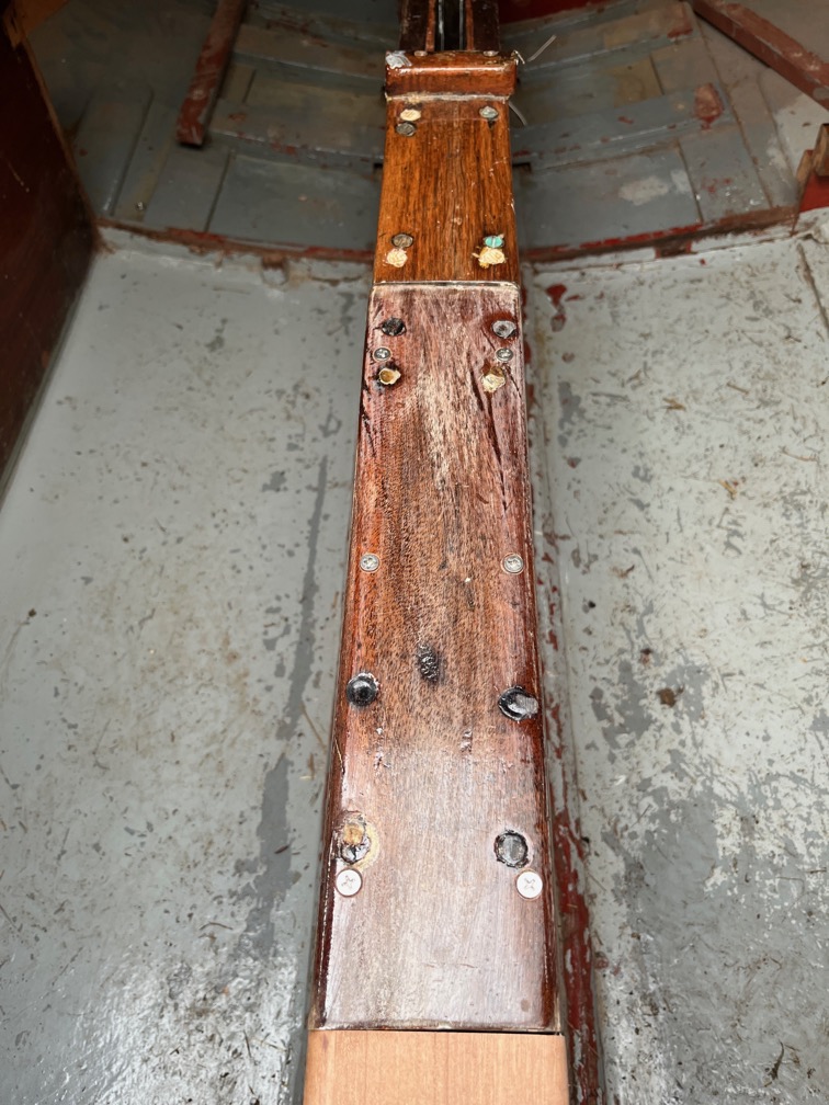
With a new sanding disk in the angle grinder I started to shape the remaining untouched part of the top of the block. Not easy due to the space restrictions, but this is close enough for the rough work and I’ll resort to something a little less aggressive to finish it off.

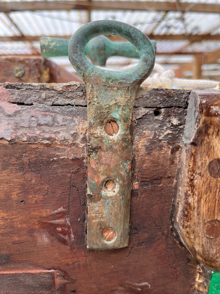
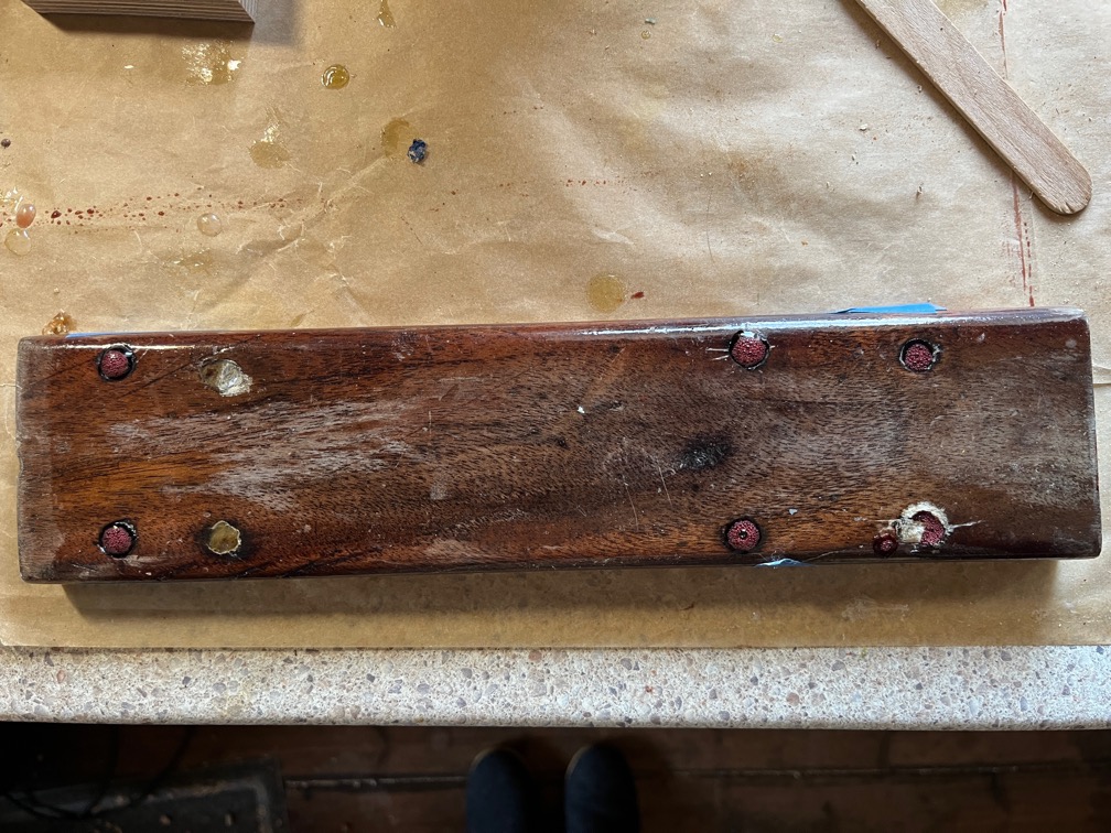
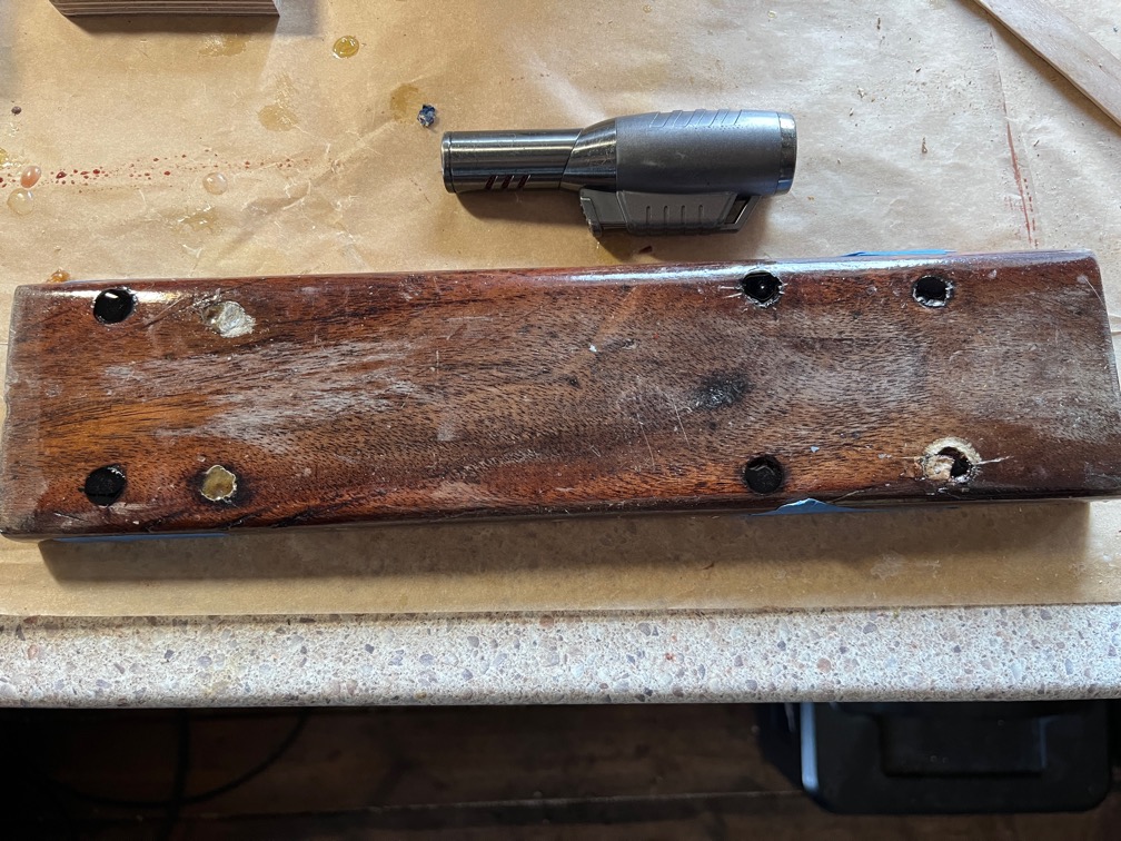
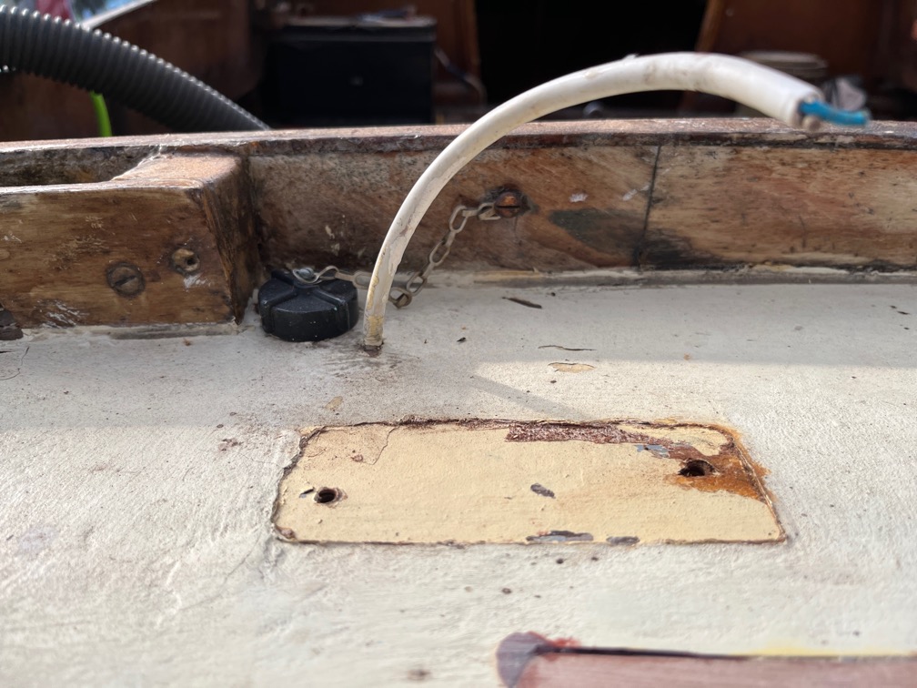
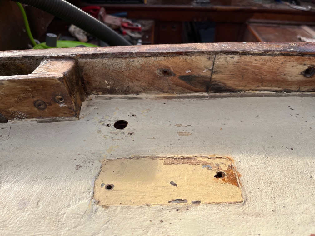
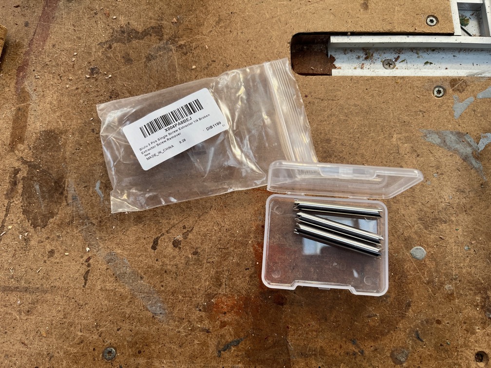
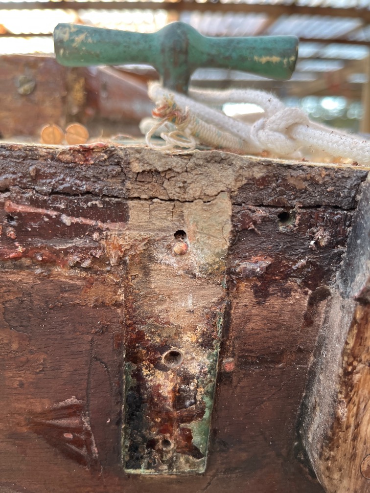
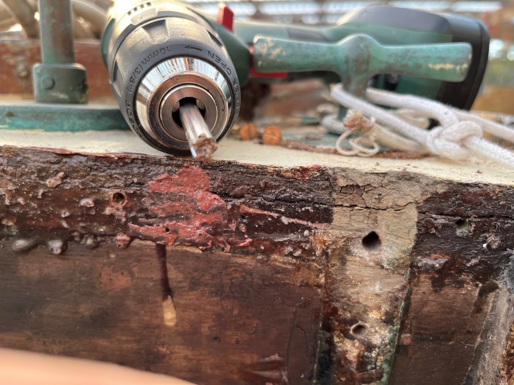
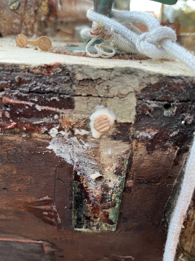
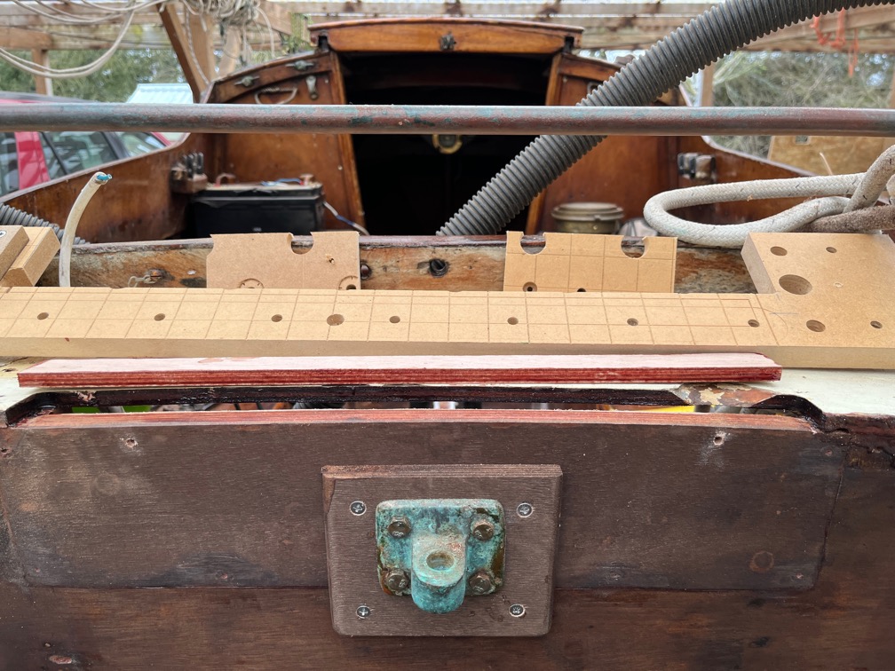
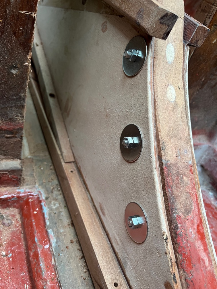
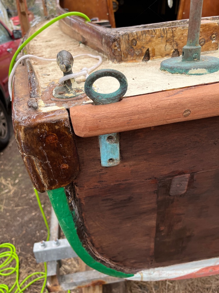
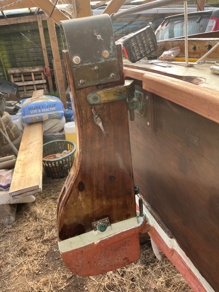
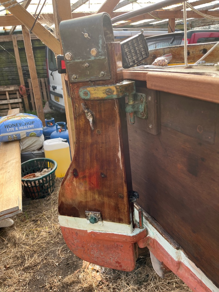
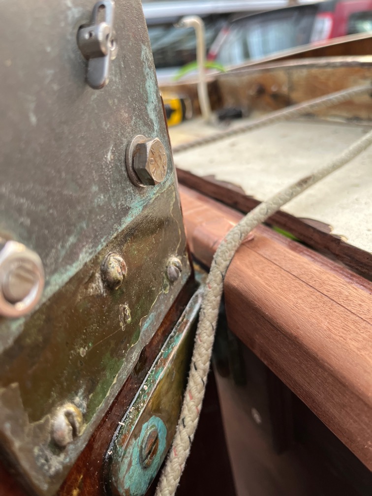
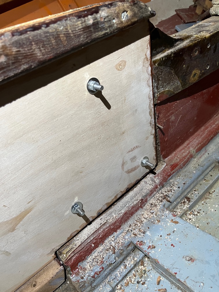
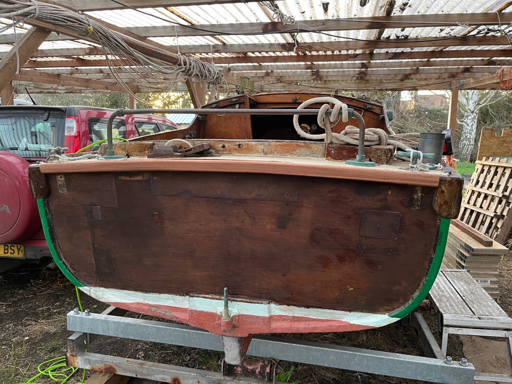
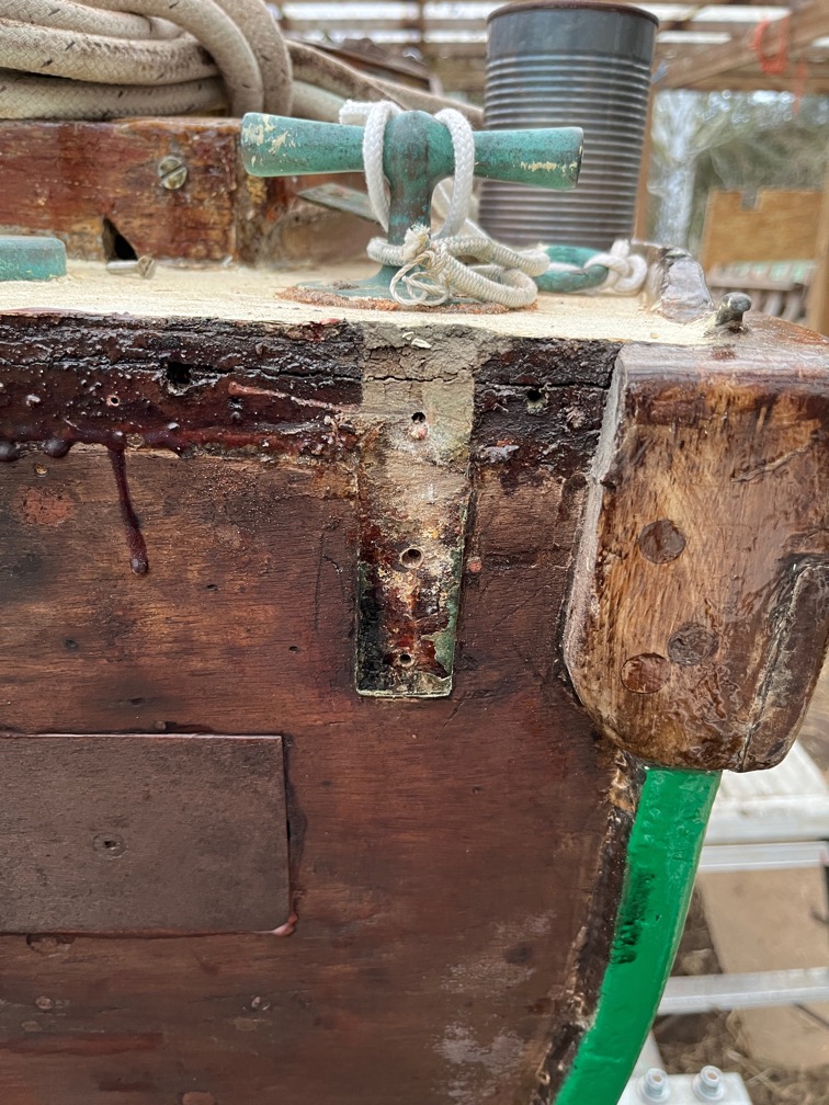
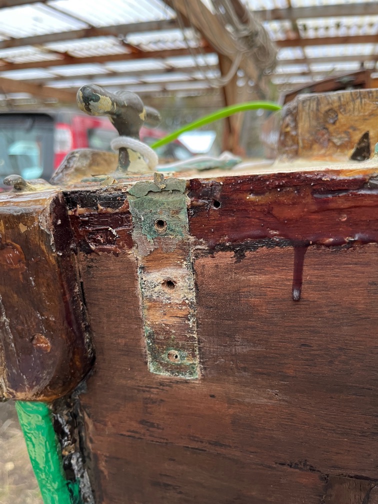
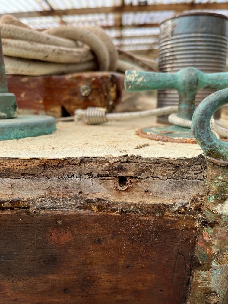
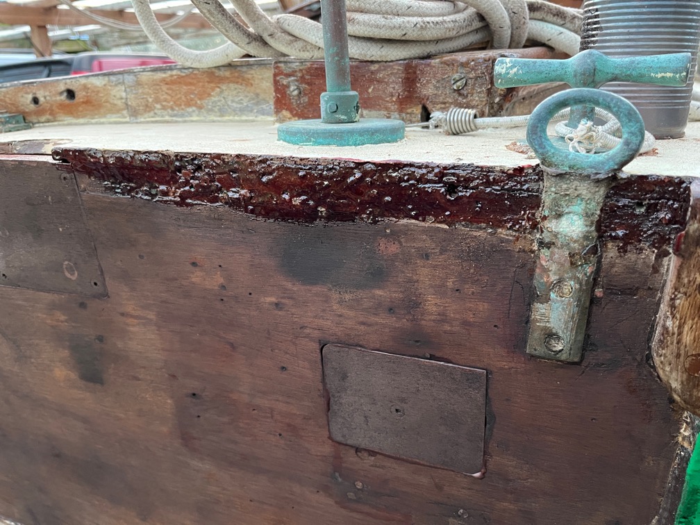
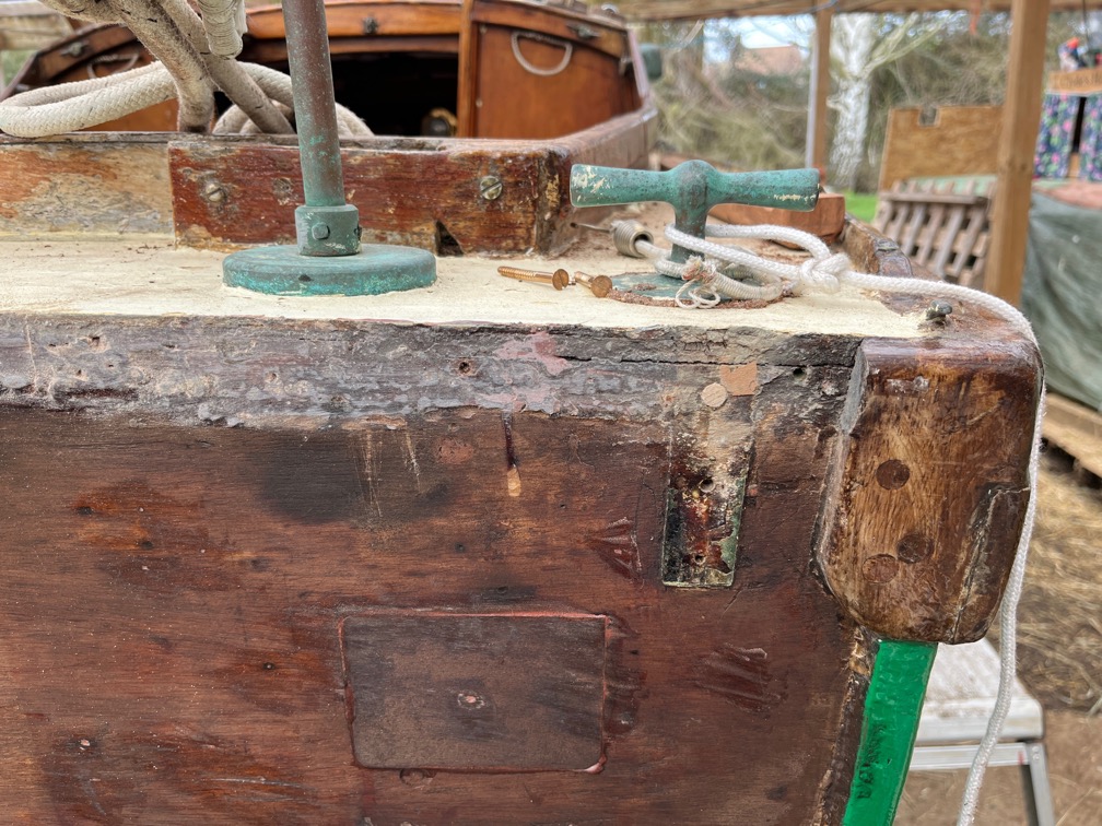
Next up was the transom eye replacement only this didn’t go as planned. There was another broken screw in the middle hole, so I had to stop what I was doing, drill out the broken screw, plug the hole and put the eye on. I’ve left the screw out of the middle hole until the glue has dried.

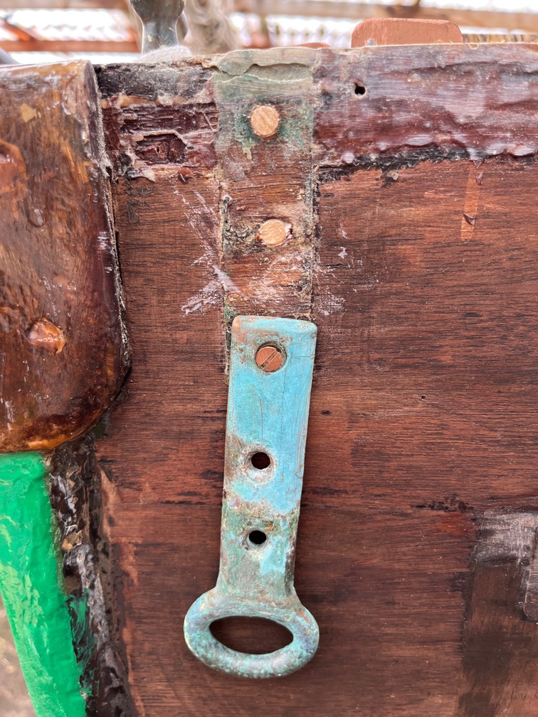
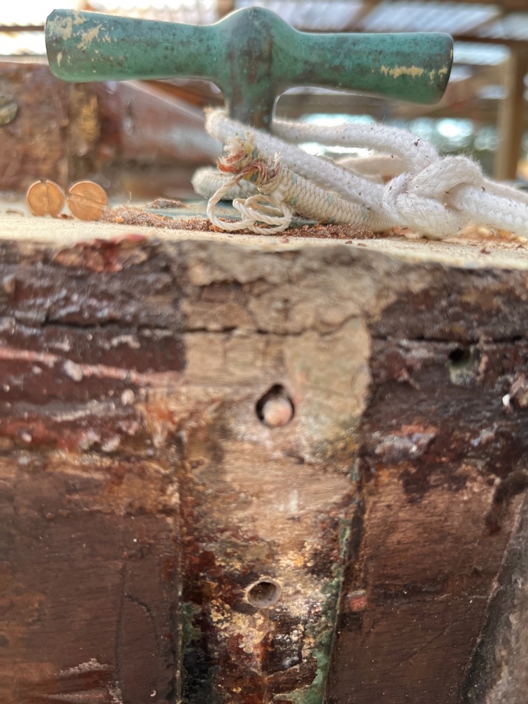
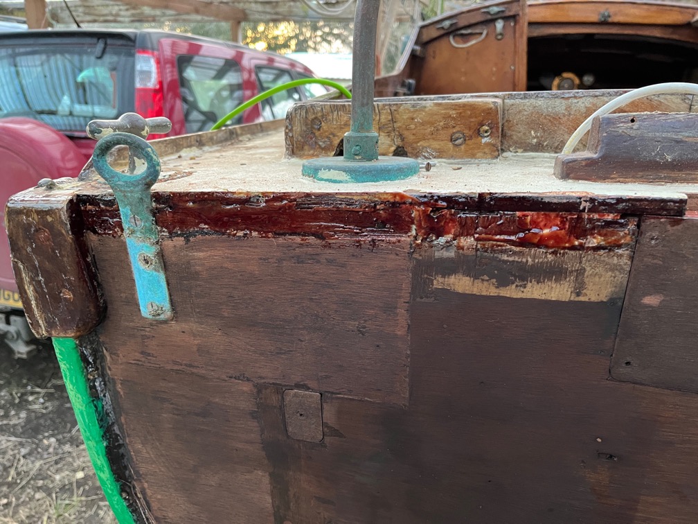
The other side was just as bad only this time the holes were too big for the screws. These also were drilled out and plugged and will be drilled with the pilot holes for the screws once the glue has dried.

Still, not bad for a lunch break, so it is back to work.

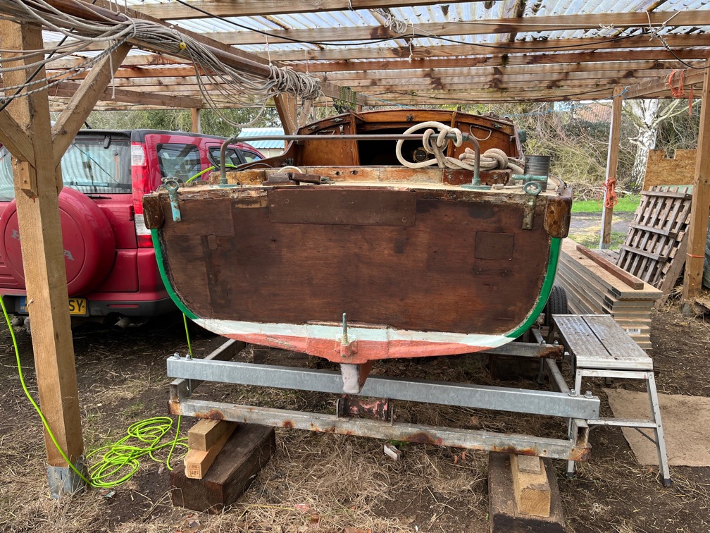
I had a reply from one of the local boatyards regarding my proposed leak test. They said that they could do it but the cast would be £504 including VAT. Far too much so after work we took a trip to other one of the local boatyards and asked then about using their launching slip. The charge would be £50 if I launched her myself or £150 if they used their launching tractor to push the trailer into the water.

We settled on my trying with out Honda CRV, which should do the trick without problems, but if I did get into trouble, then they would use the tractor to sort things out. Next Thursday is leak test day ! I need to visit the cash machine.

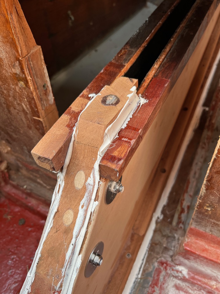
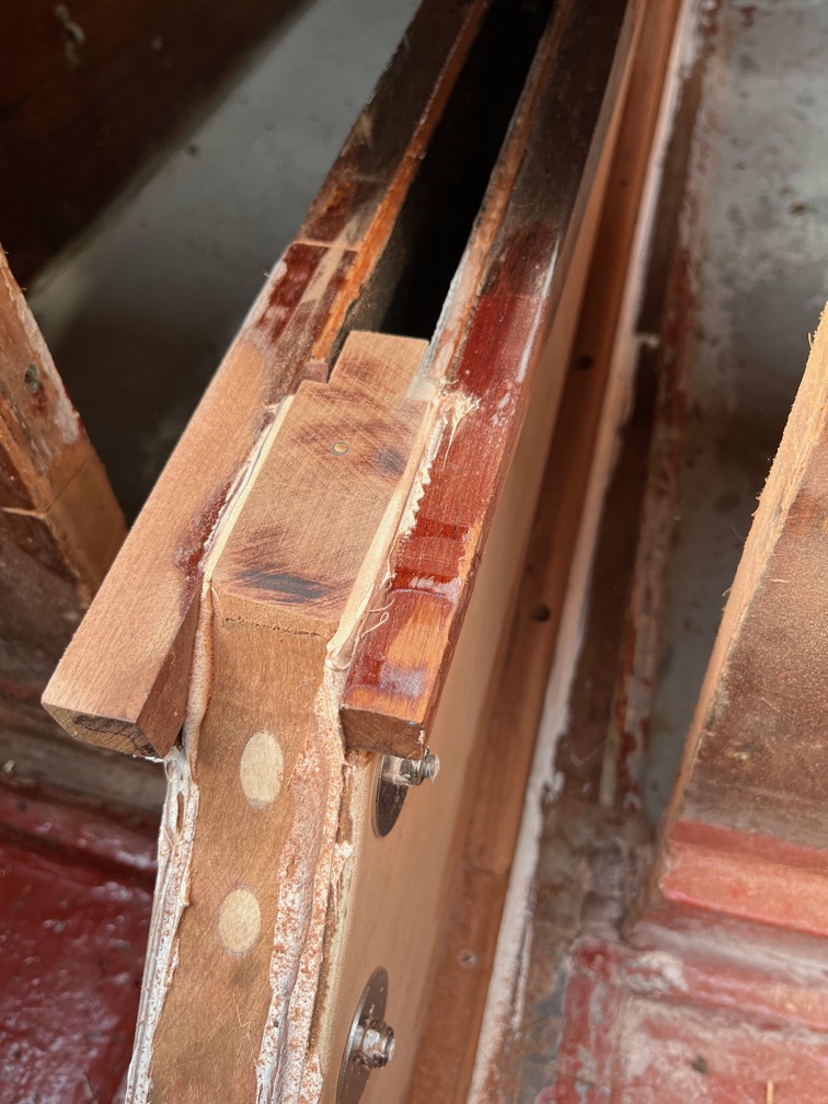
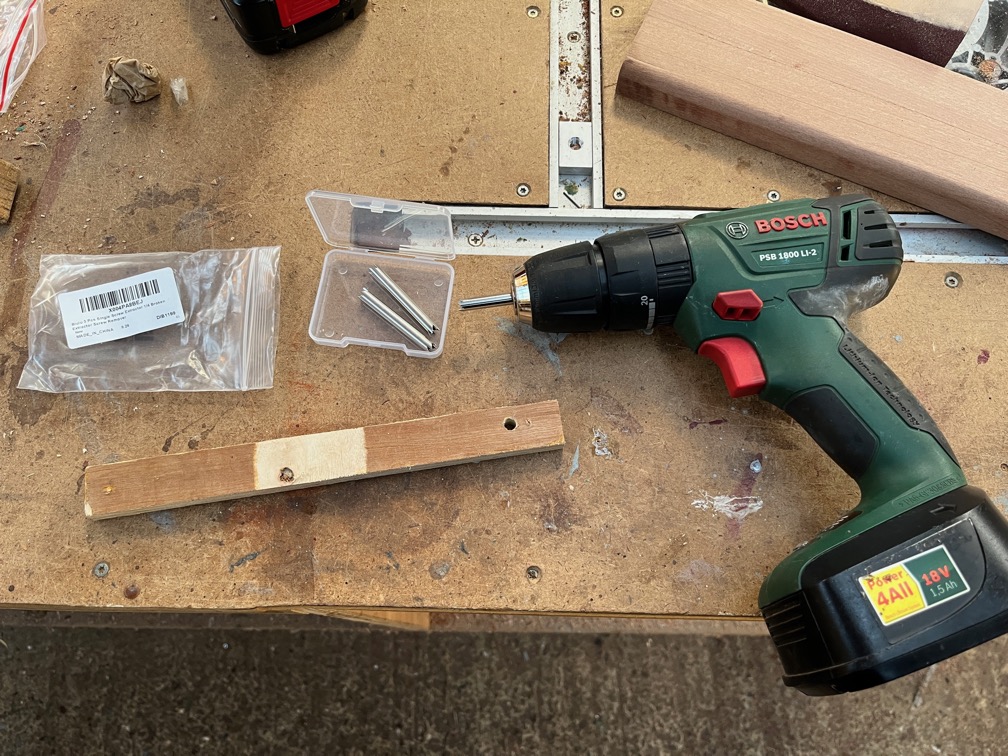
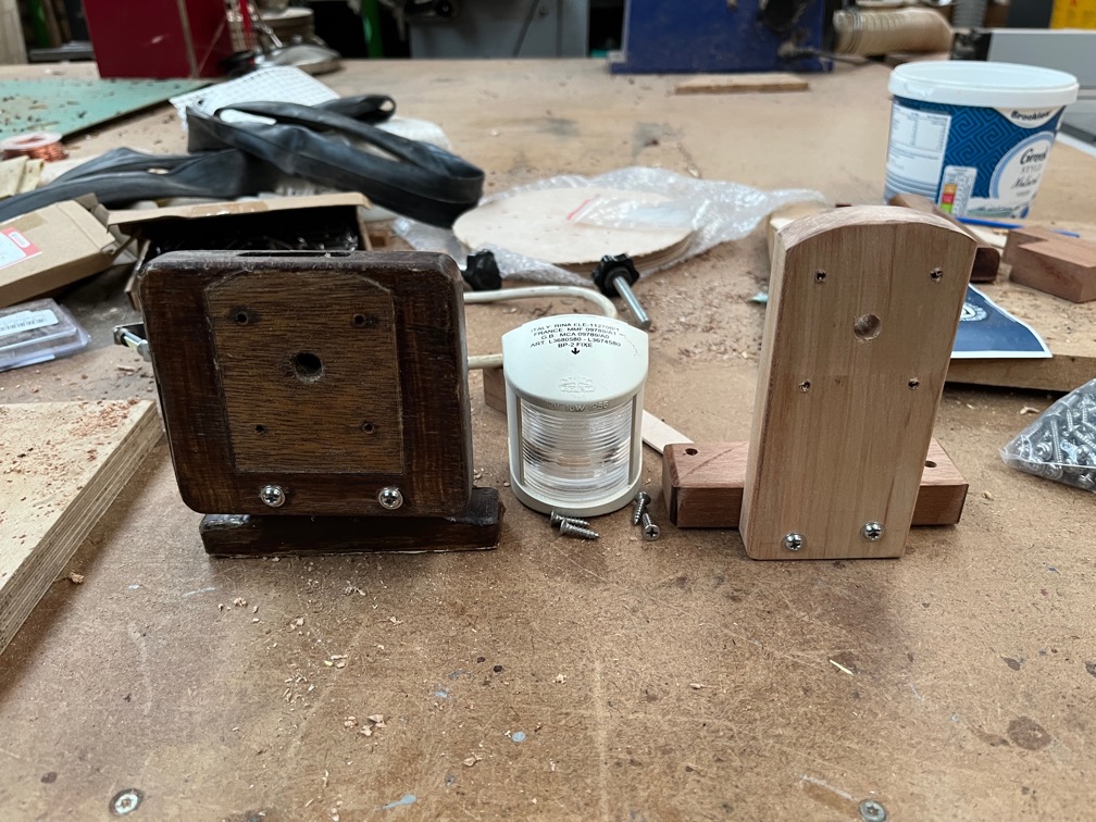
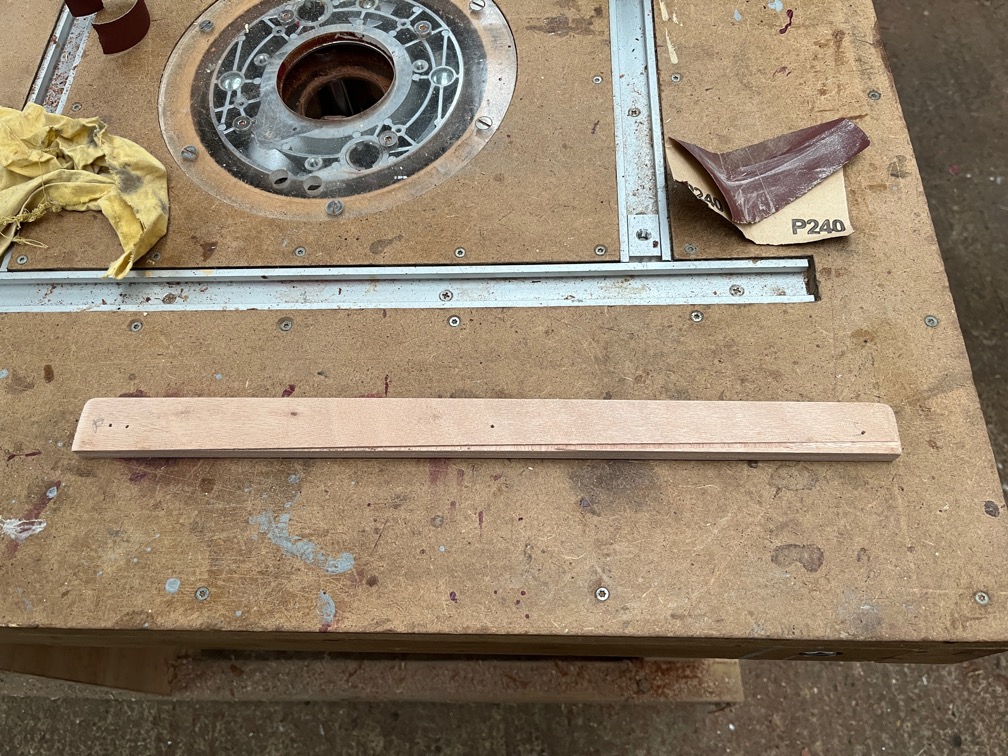
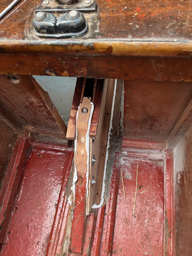
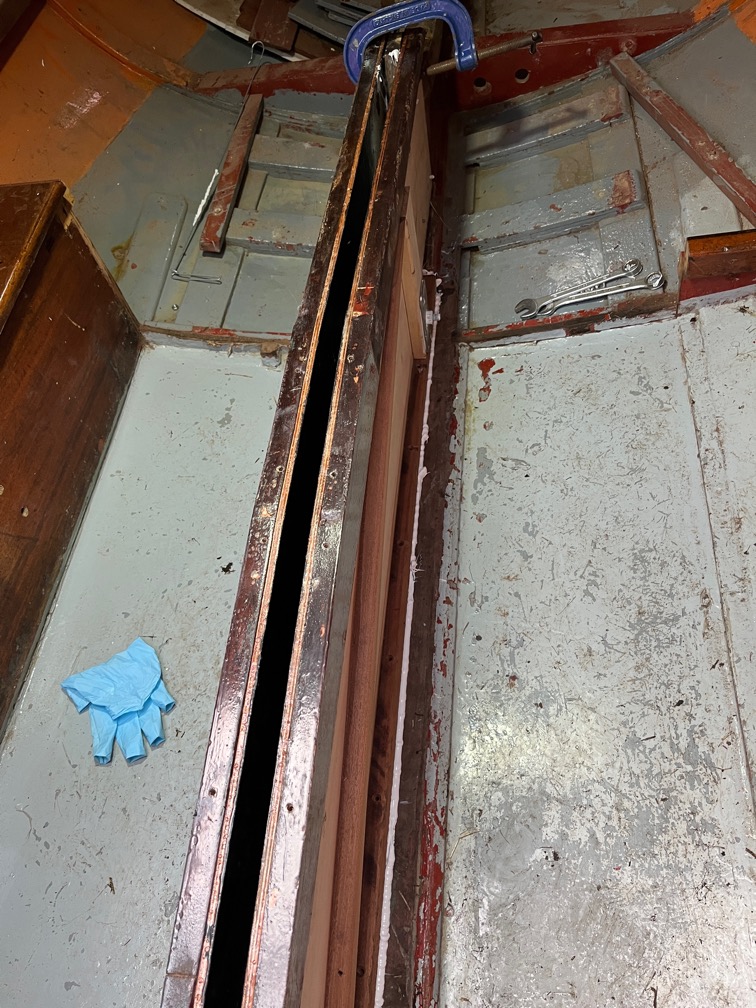
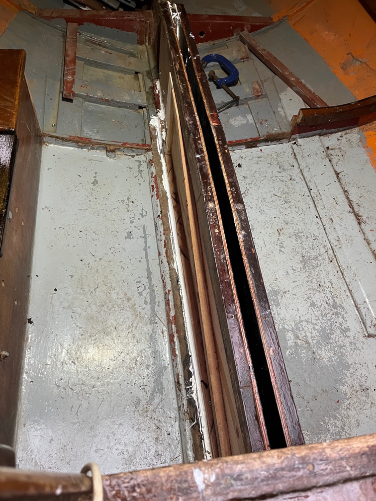
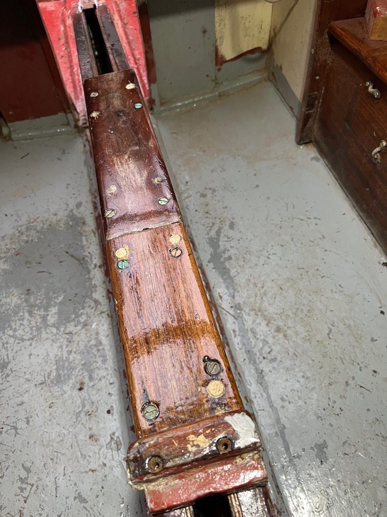
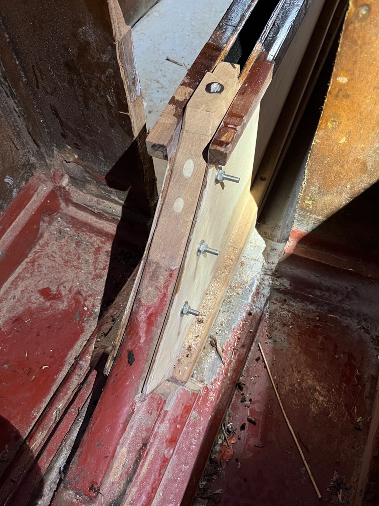
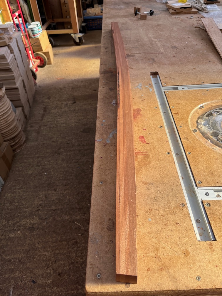
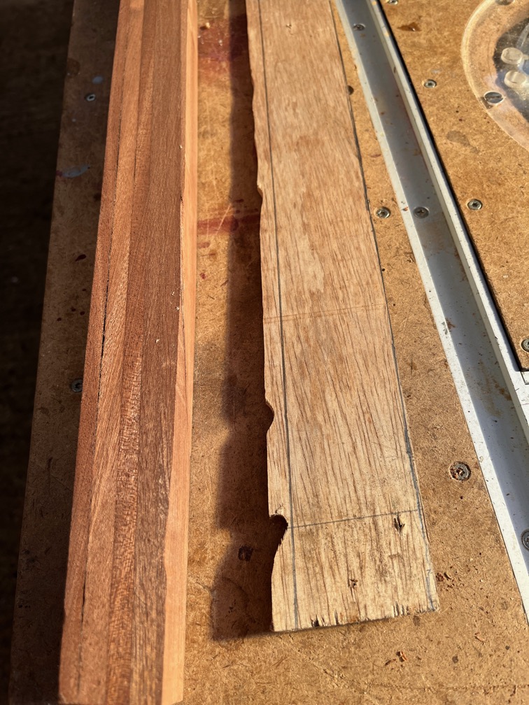
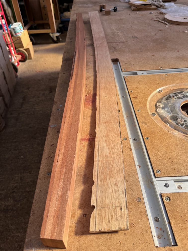
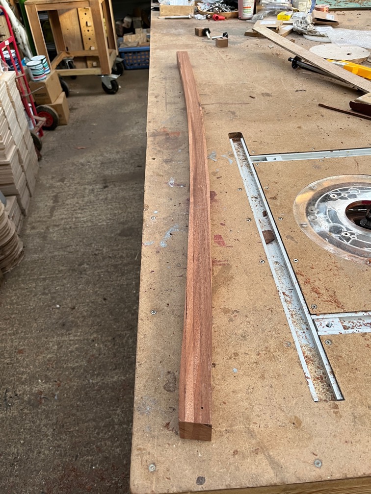
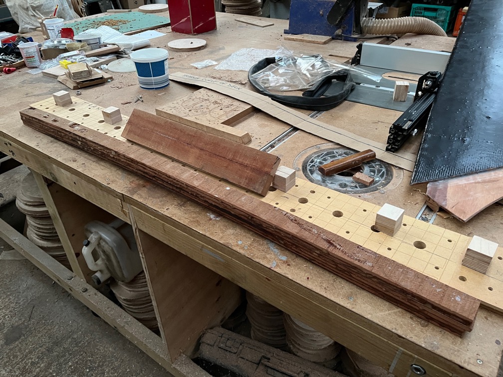
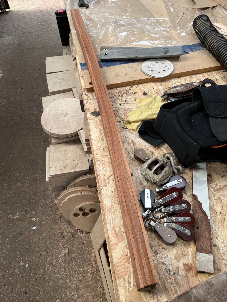
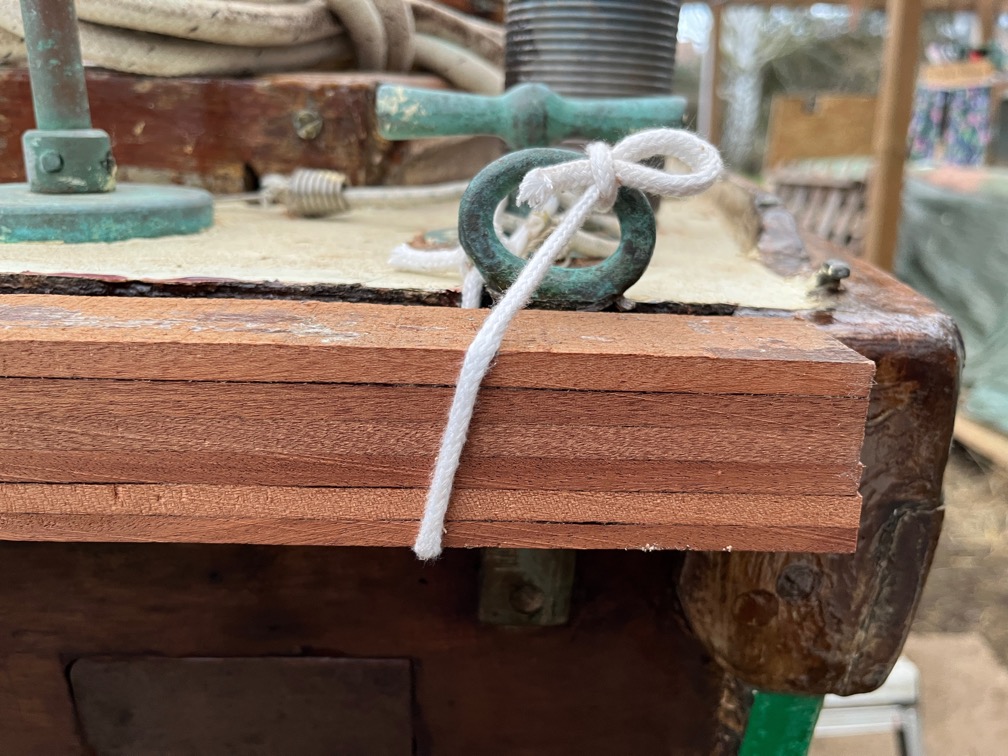
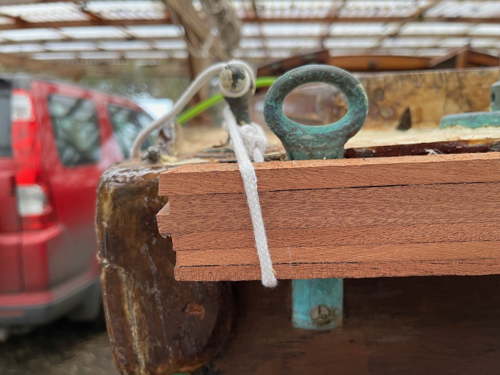
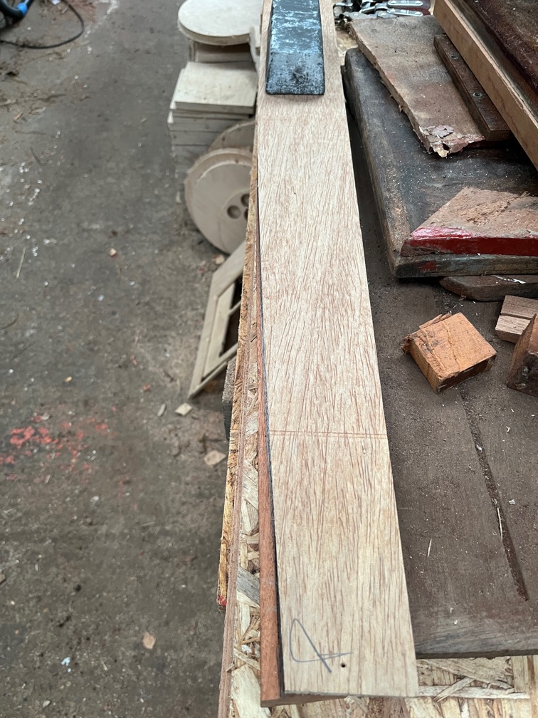
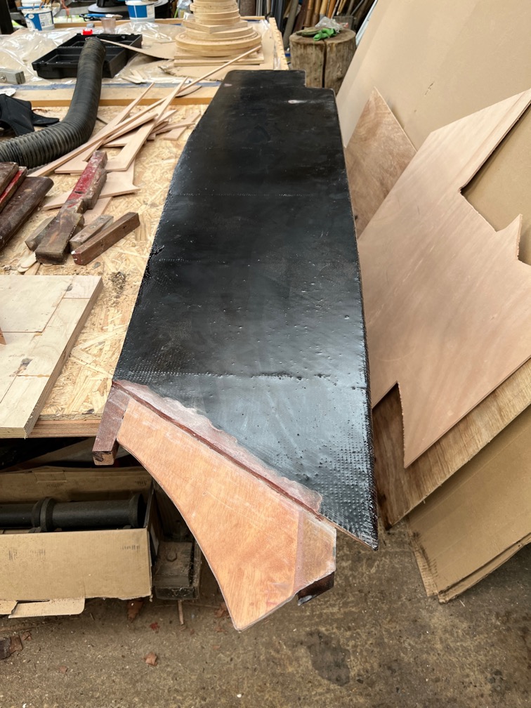
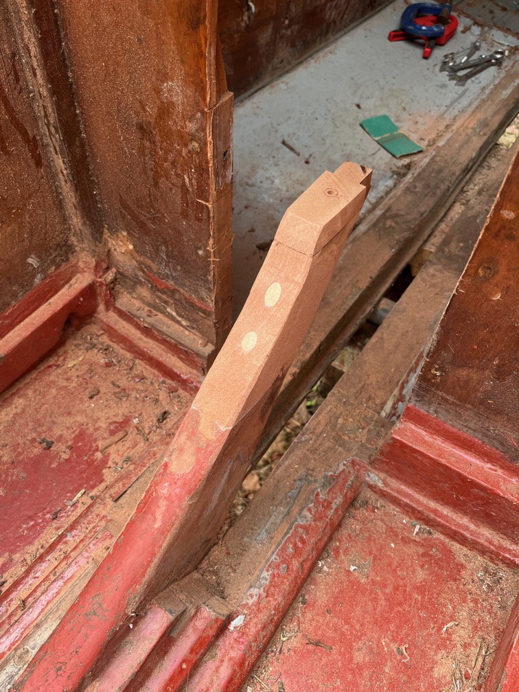
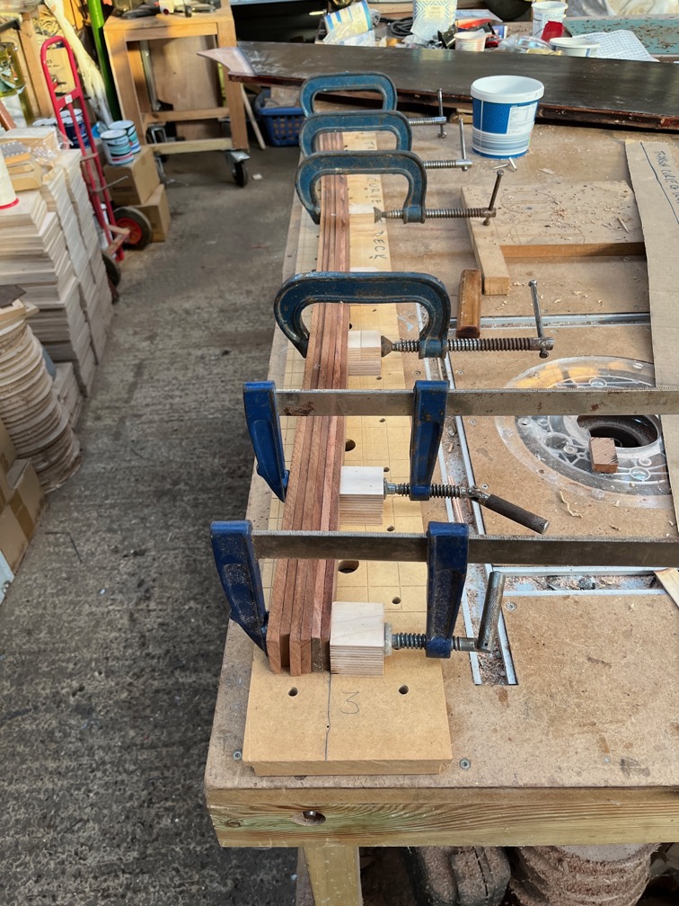
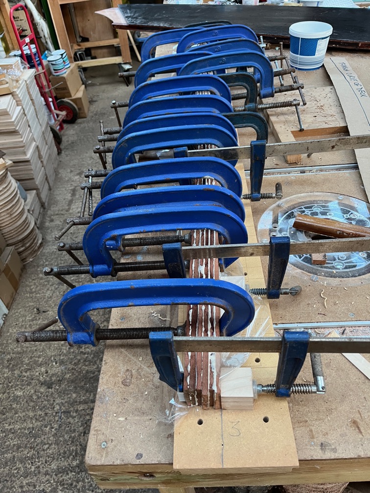
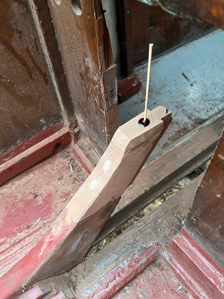
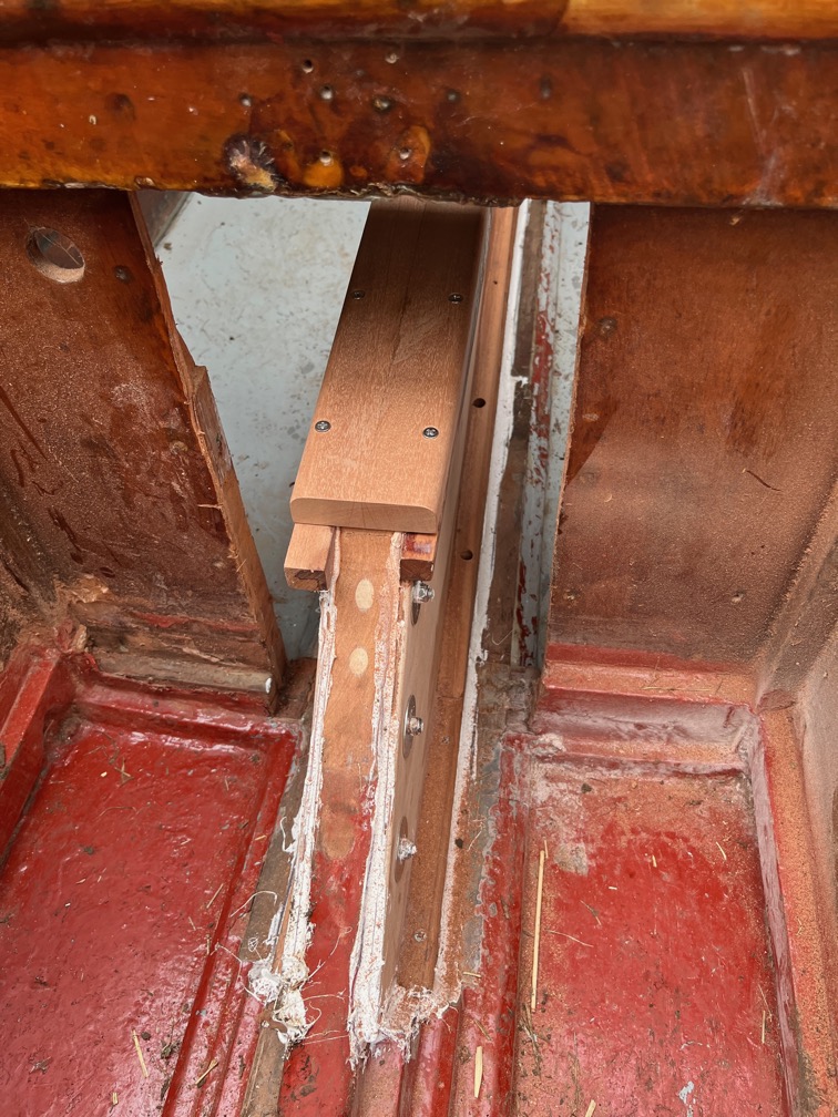
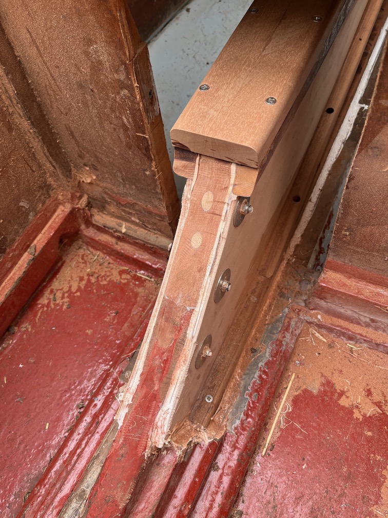
On arrival home I started work on one of the case supports for which I have the original timber. It needed some adjustment as the new case side is slightly different to the old and it was also too short having been cut out of the bottom runners.

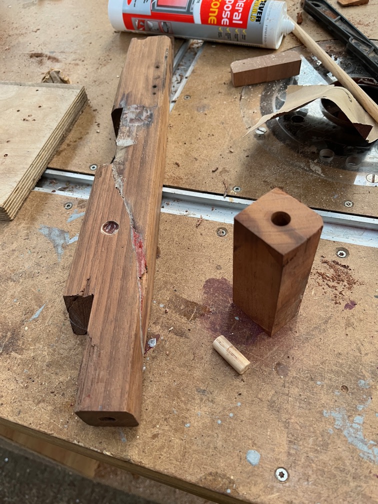
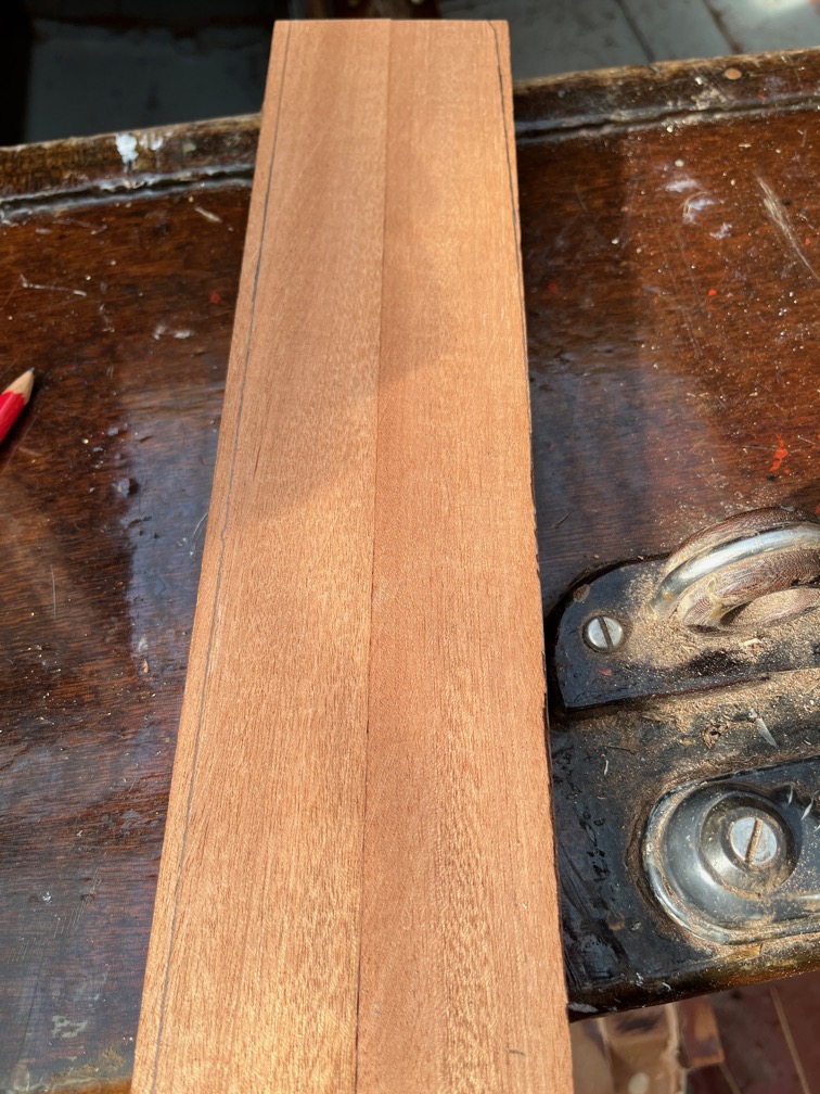
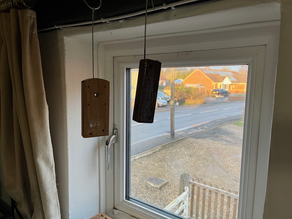
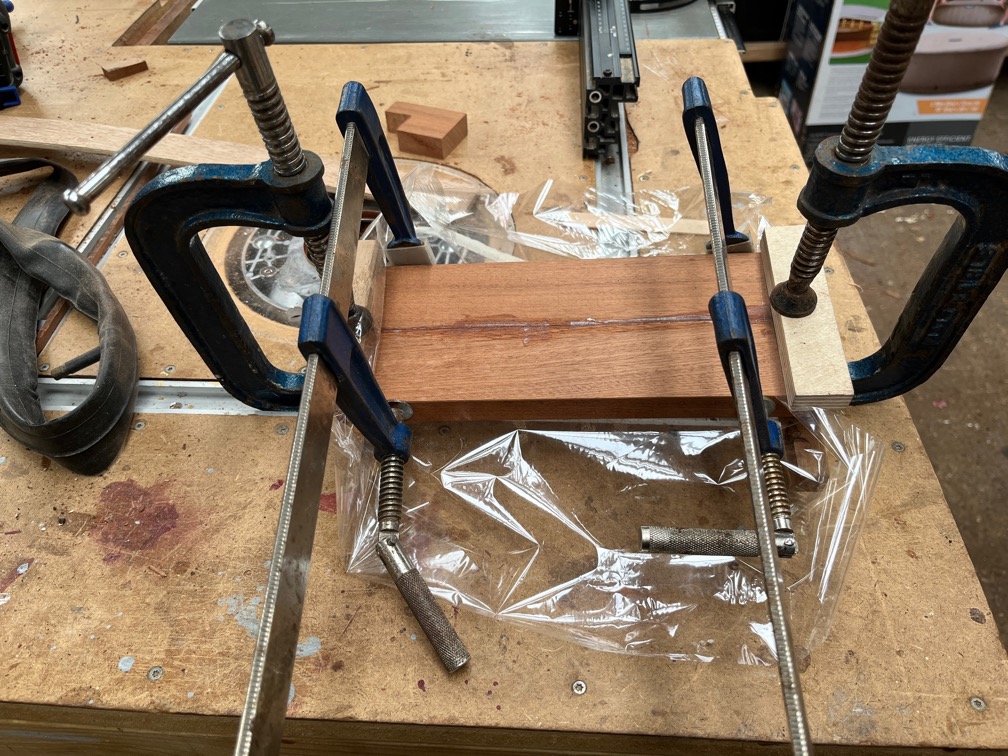
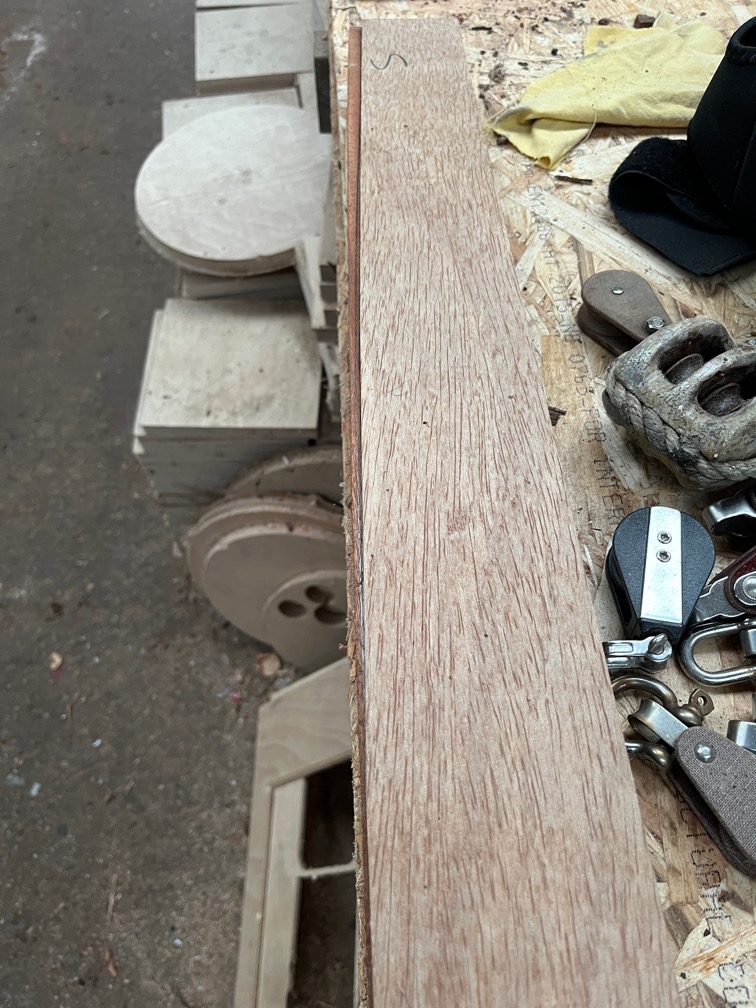
So, here are the pieces, the original support and the extension which will be glued to the bottom and located with a dowel.

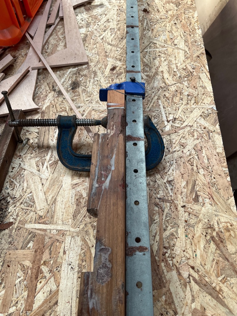
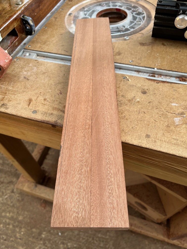
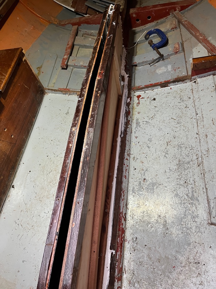
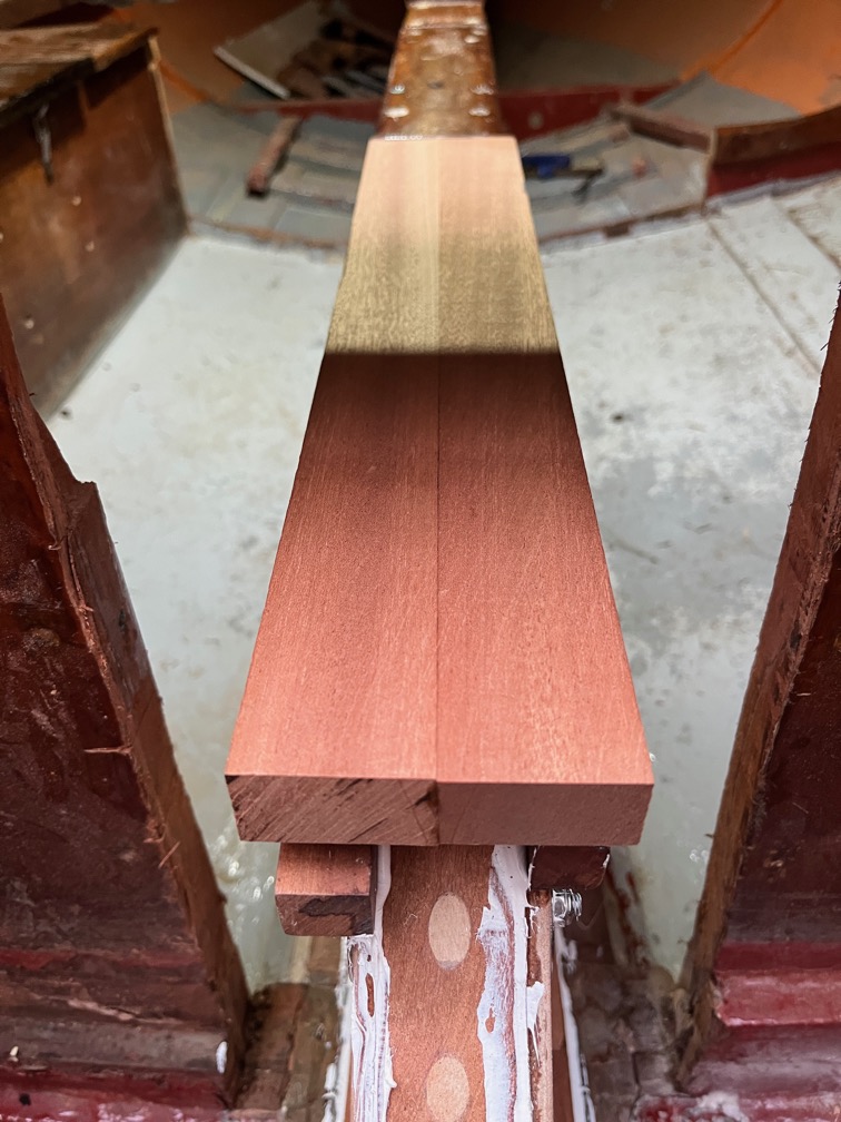
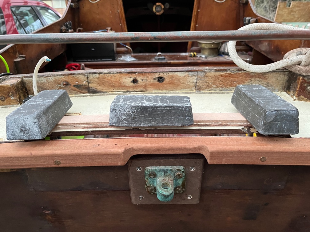
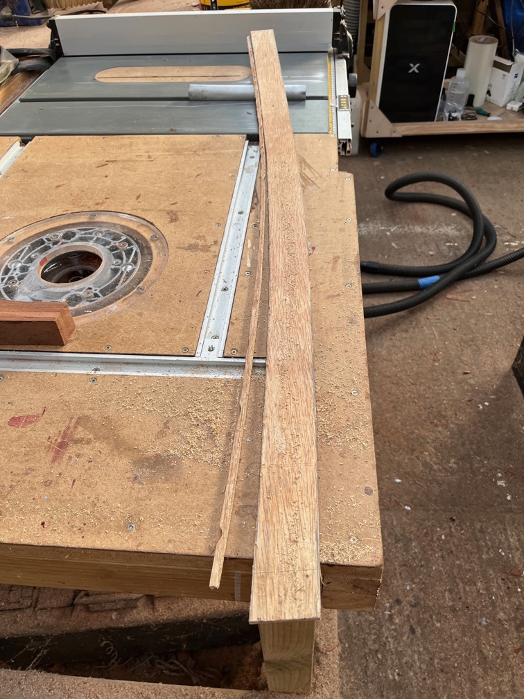
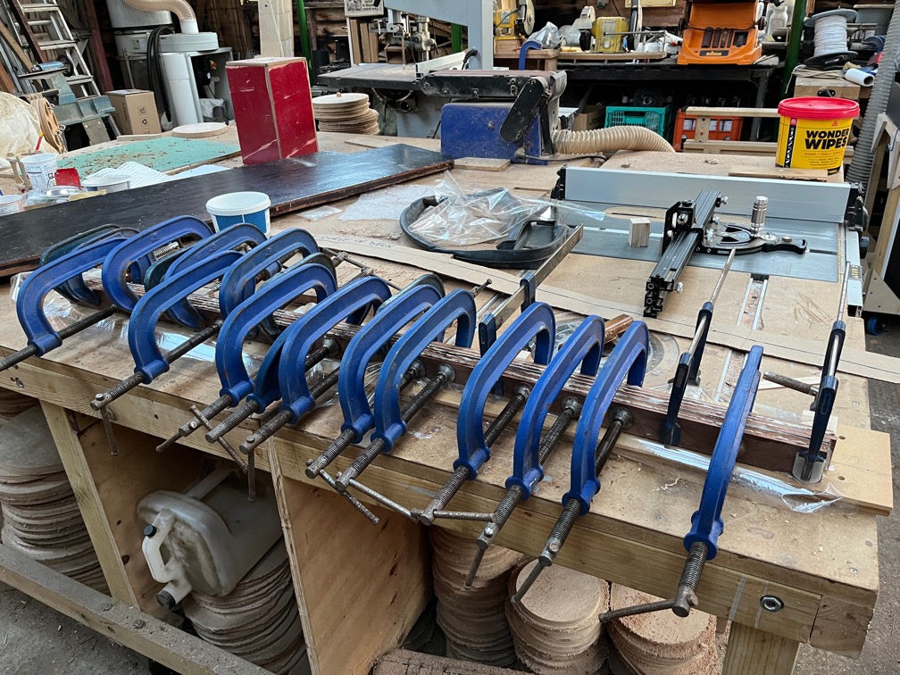
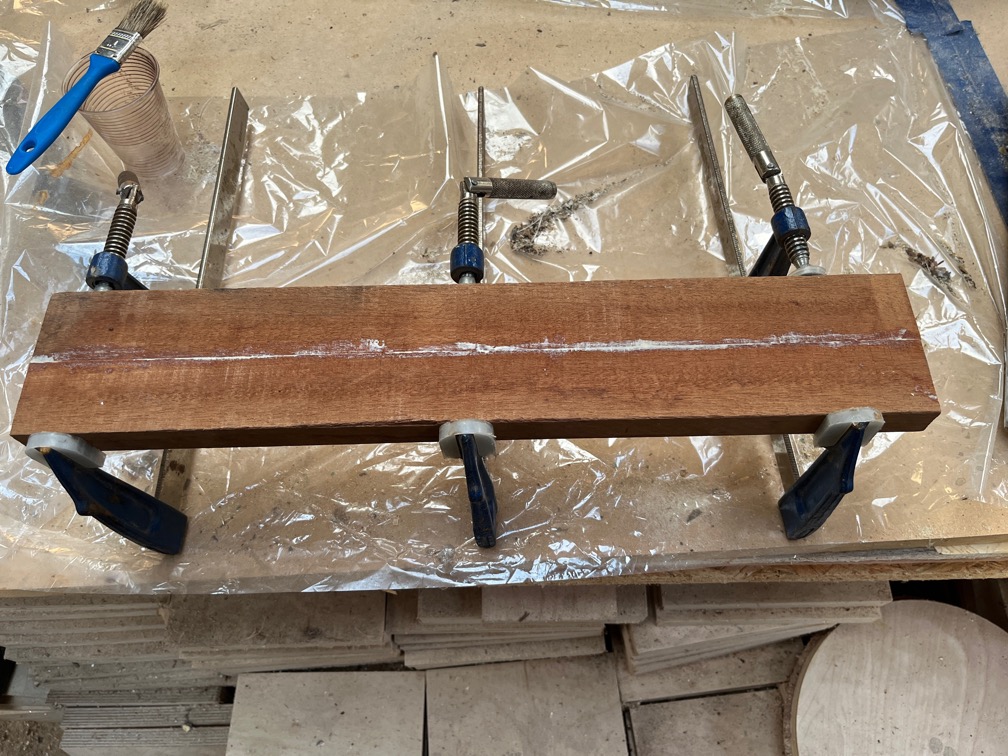
The pieces were clamped together to ensure a tight joint.

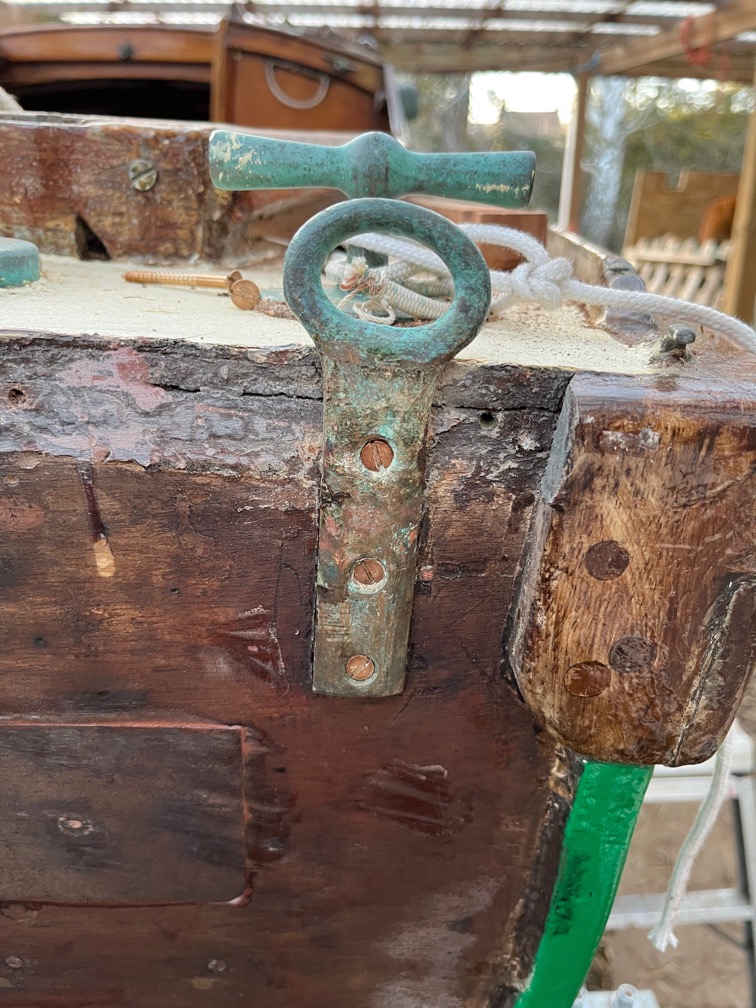
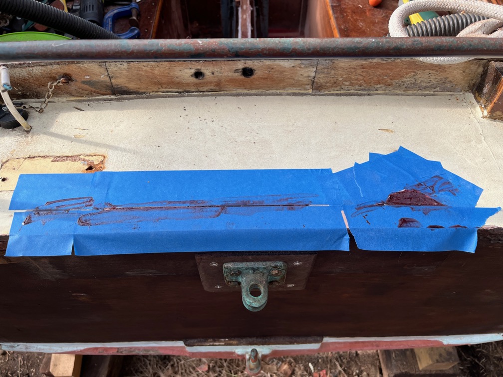
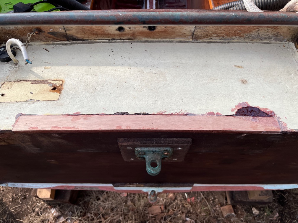
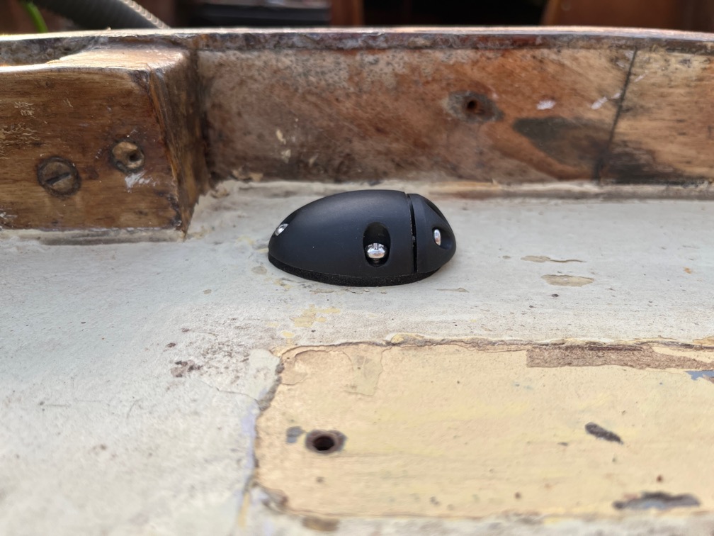
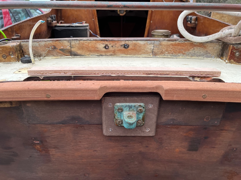
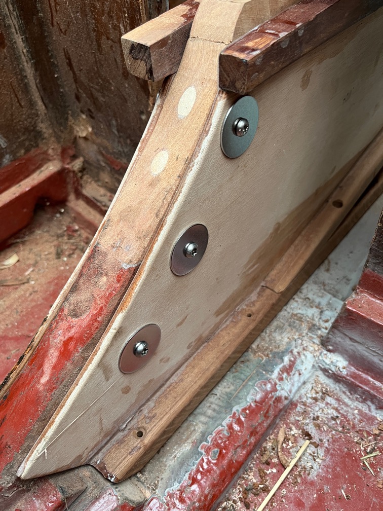
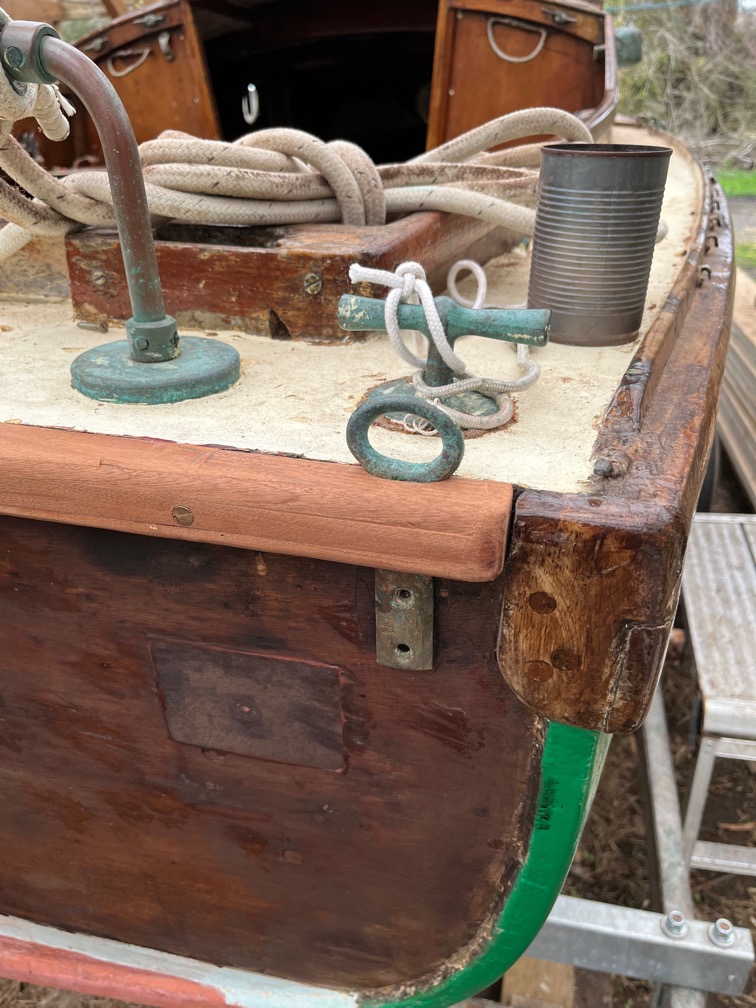
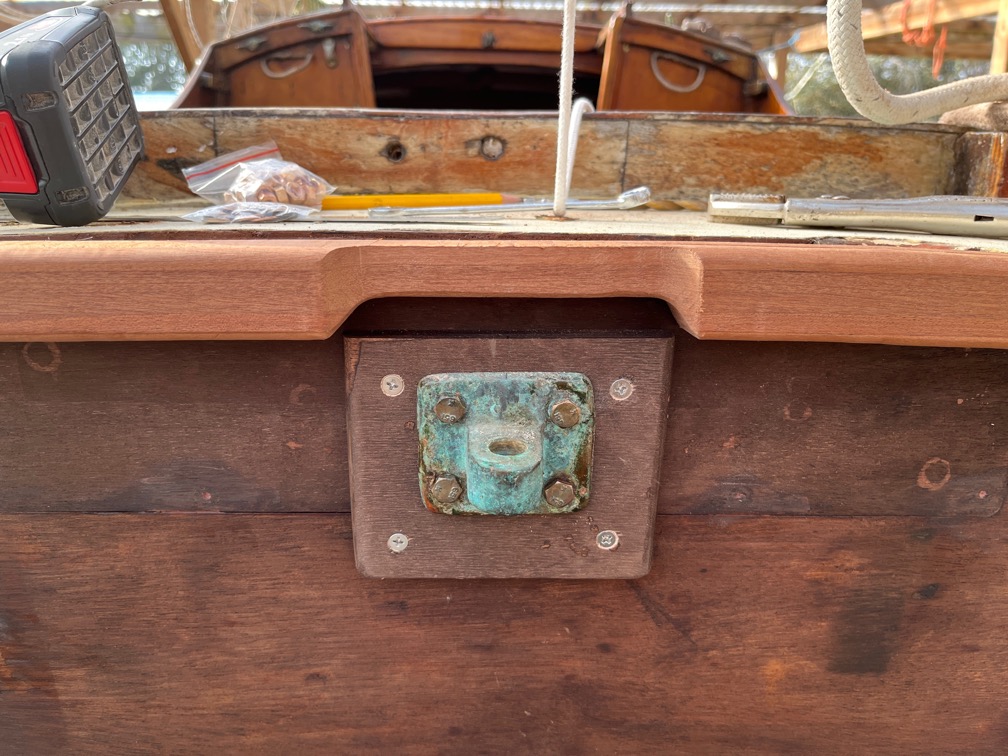
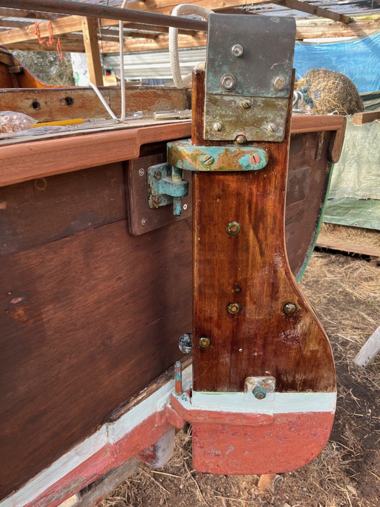
After that I went out to the transom and completed the dry fitting of the eyes.

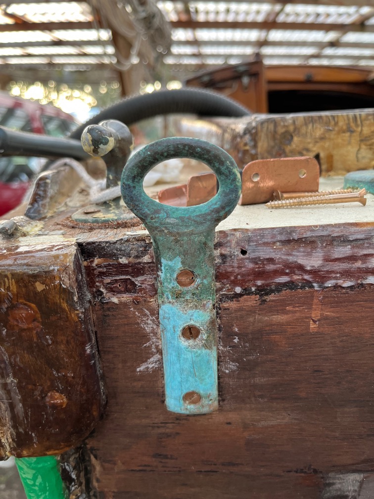
Both of these are now a good fit and ready for the assembly.

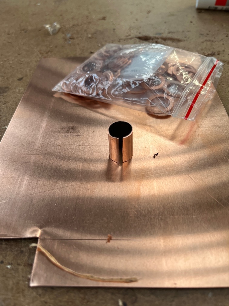
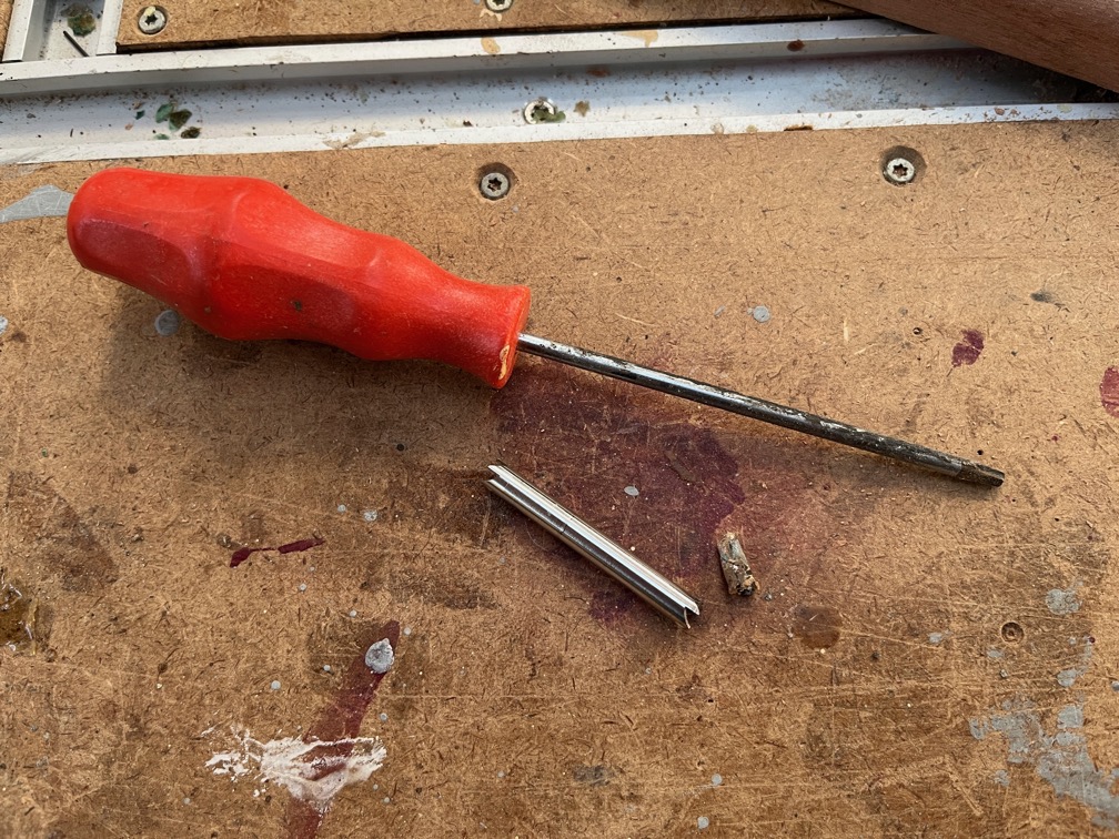
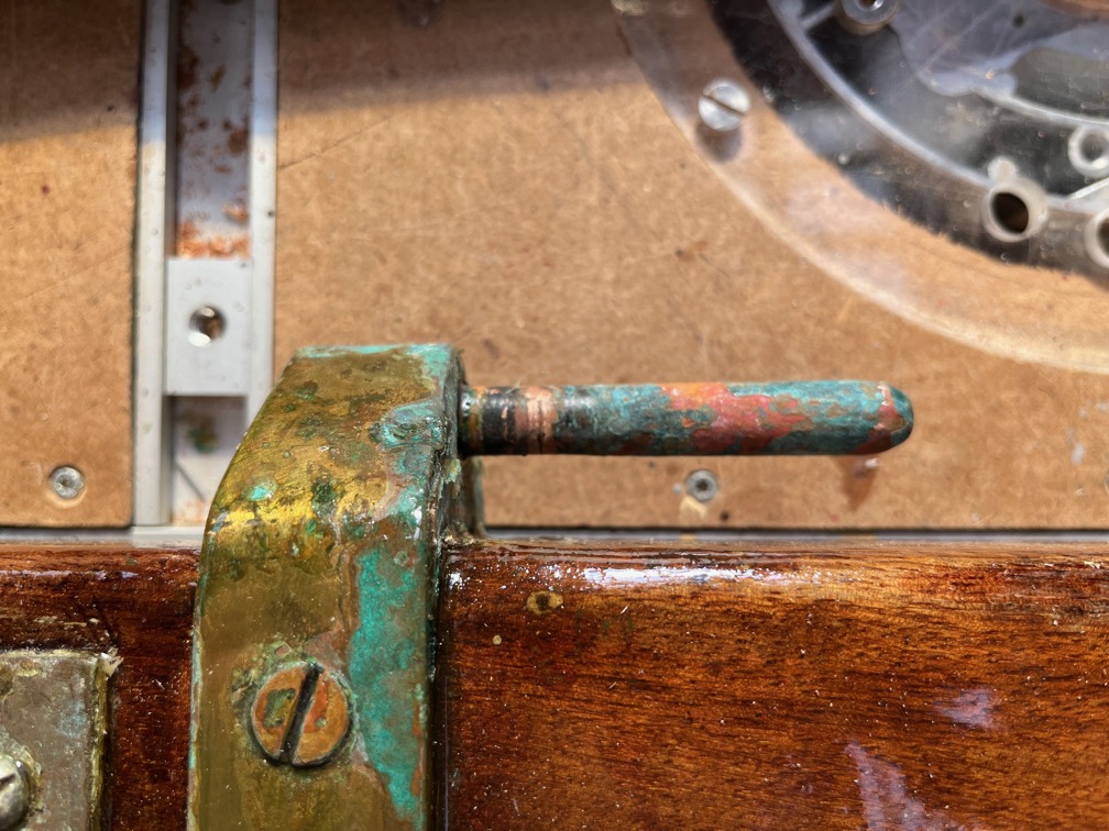
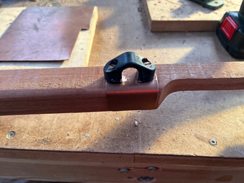
The thin copper sheet arrive this afternoon in the post, so the next task was to make a small copper cylinder for the pintle on the rudder stock. The trick with making rings or cylinders from sheet material is to shape the ends first. You never get a good result if you start in the middle and work towards the ends, they always turn out flat. The mechanics part of my degree in Electronics was useful for something !

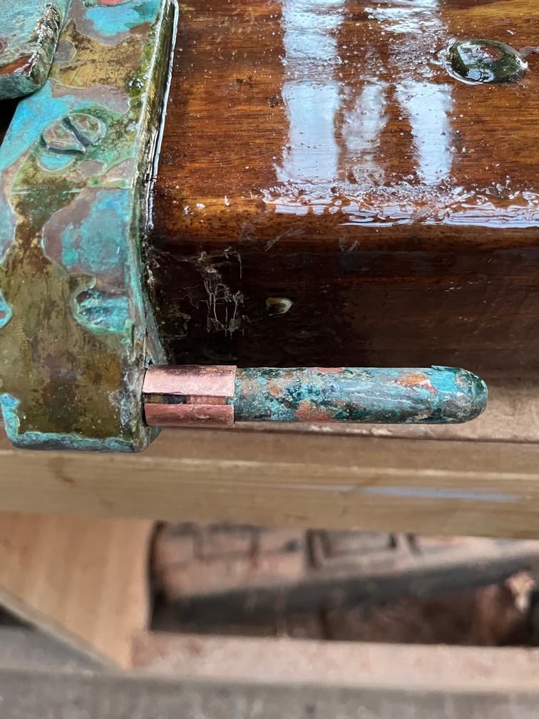
The cylinder was made just a little short of completely around the pintle, as you can see here, to allow for the cylinder to be put on over the slightly larger end.

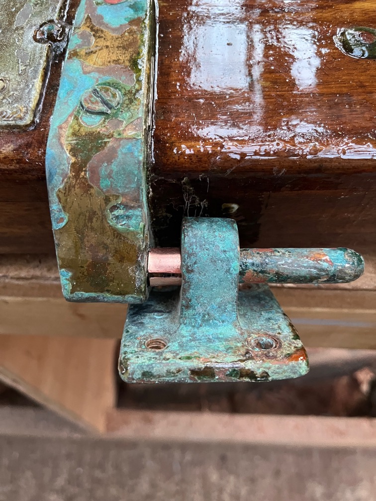
The gudgeon slips on quite nicely, so this part of the task was a success.

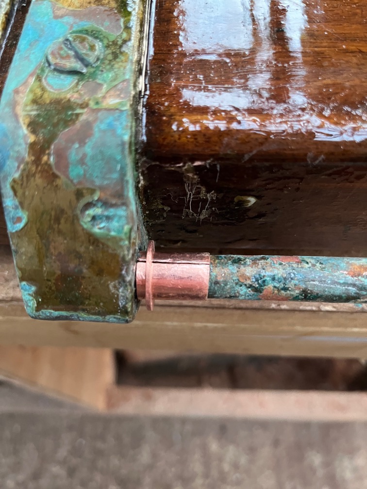
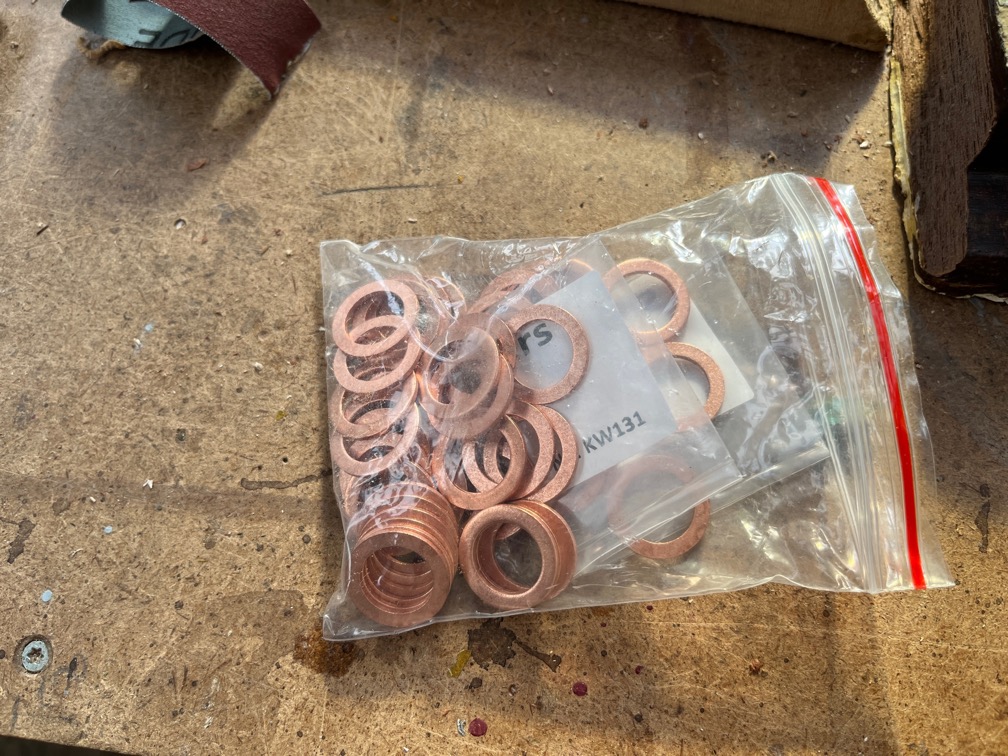
The copper washers also fit onto the cylinder.

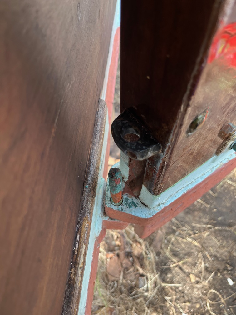
This raises the issue that the gudgeon can be mounted on the transom higher than it is now. So I cut a larger piece of copper and made a longer cylinder.

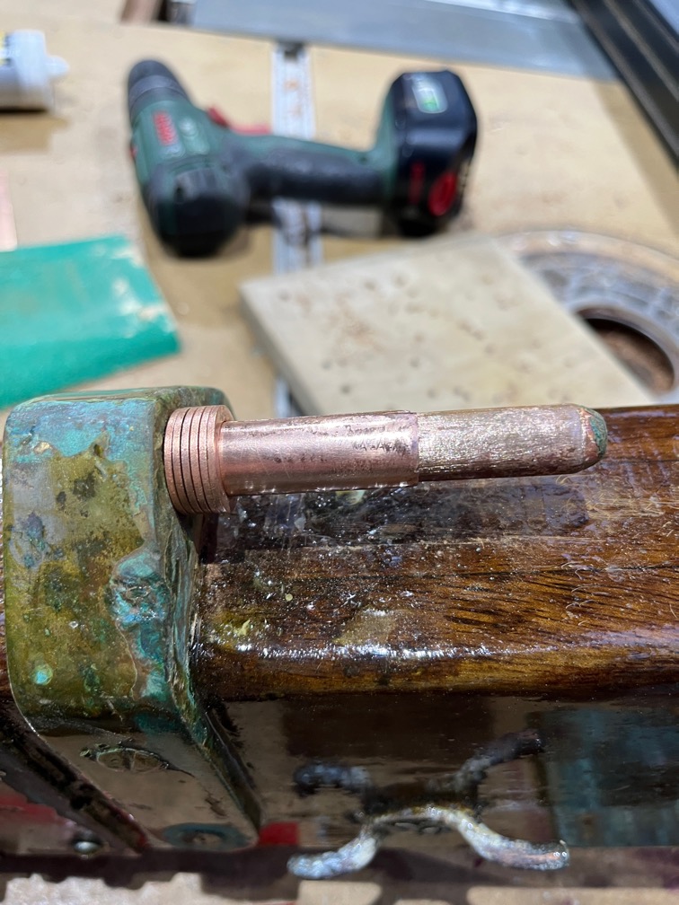
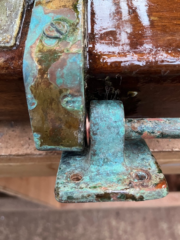
I have to clean the varnish and verdigris of the pintle, but the larger cylinder went on well as did the washers although these were quite tight. A good thing as they stop the cylinder from just falling off. I’ll still need to put some glue on, but it is good that they are a tight fit.

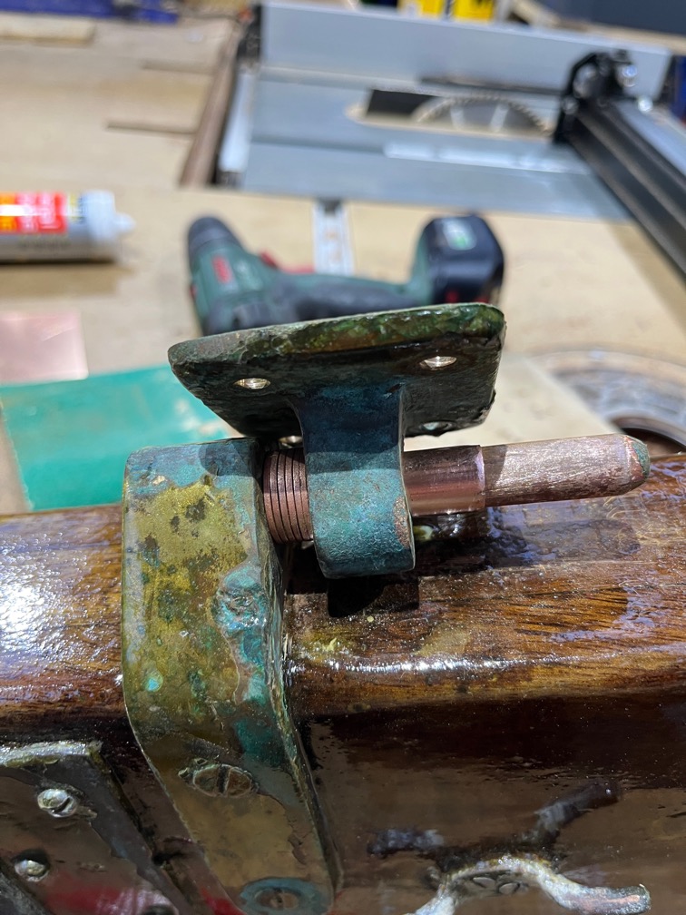
The gudgeon also fits well over the longer copper and is a snug fit, no play at all. This makes me wonder about doing the same thing for the pintle on the transom.

I’ll think about that. Maybe another time.

So, a very productive day with things moving one. Just as well since I now need to make the gantry crane before Wednesday next week.

Oh the pain, the pain!

Time for a cup of tea.

2026-03-02 – Aft Deck & Other Rebuilding

The first thing on my list of tasks for the day was the varnishing. There’s not much to it, takes about ten minutes, but it still needs to be done.

After that it was time to see how the aft deck is doing. With the clamping piece and baking paper removed, the result is looking slightly messy but good.

The major ding in the deck has filled well, but there are a few areas that need a little more epoxy to filling the parts where the epoxy has sagged down a little into the seams and left a void.

Nothing important, but needs to be filled. Tapping the area on and around the new piece gives a sound return, so it looks like that graving piece has worked.

The whole area and transom will be finished in the coming days.

The next in a sequence of tasks is to shape the top of the new aft block.

This is the start of the centerplate case reinforcement, essential to keep the case from moving from side to side under the stress of the plate when sailing. There are three supports in Shoal Waters, one just in front of the pivot bolt consisting of two half-bulkheads and provide the main reinforcement. The pivot bolt is where the most lateral stress will be applied to the case.

The next support is at the forward edge of the bridge deck and the function of this support is three-fold. Firstly it provides support to the case. Secondly it provides support to the forward edge of the bridge deck and thirdly, it provides an anchor point for the plate uphaul.

The third support is found at the aft edge of the bridge deck. The primary purpose of the support is to provide an edge to the half bulkhead that forms the front of the cockpit well. It is sealed against the case such that any water that gets into the cockpit does not immediately drain into the cabin. As a secondary function, it also supports the case but is not really required at this point as only the tip of the plate reaches this far back in the boat and when the plate is raised up that high, the sideways force on the case is very small.

However, all three supports need to be put back but in such a way that they may be easily removed. They will not be permanently fixed until after the leak test.

The sealant has dried well here so I can cut the top off with a pull-saw.

This did not take long and the is the result after a quick sand to remove any saw marks.

The piece of timber for the new top cover was placed into position after squaring off what will be the forward end and the shape of the underlying case drawn in pencil.

I shaped one side first using a bandsaw followed by the belt sander. I offered the workpiece up to the case again and checked that the pencil mark was still correct before shaping the other side.

Having carried out the check I shaped the other side and gave the top side corners a round over.

The top was given a light sanding as this will be varnished, although not much of it will be seen.

At this point I decided that I would remove the piece to which this piece buts on the top of the case as it has gone on slightly skew. I knocked out as many of the old, broken screws as I could, taped the underside and filled the holes with neat epoxy.

I didn’t thicken the epoxy as I wanted it to run down into the holes. The disadvantage of doing this is that the bubbles you get when mixing the epoxy rise to the surface as you can see here.

The solution to this is either to use a vacuum pot to suck out all the bubbles before you use the epoxy, or heat the surface of the epoxy with a hot air gun or a flame from a gas lighter. The result is pretty to watch but you do have to be careful not to burn the wood or varnish.

I had quite a lot of epoxy left over after filling the holes, so I taped up the aft deck and used some of it to fill in the gaps here. I noticed whilst doing this that the epoxy still left in the pot was getting very hot indicating that it had already kicked off. Hopefully that will mean that the epoxy work I’ve just done will cure quickly as well.

Since the epoxy looked as though it was curing quite rapidly, it was 16º C at the time, I went out during my afternoon tea break and pulled the tape off.

Removing the tape before the epoxy cures hard is fairly easy as long as you were nitrile gloves otherwise you get semi-cured epoxy all over your hands and if you are not careful, your clothes as well.

Messy!

Still, the result is quite good.

This is the place where the aft navigation light is mounted and I decided that I’d finish my tea break by cleaning the area up a little. The nav light used to have a through deck power fitting that was a socket in the deck and the plug on the end of the cable attached to the light. The deck fitting that was removed sometime ago, but the cap left behind, so that came off. The cable was pulled through from below, the hole drilled out to 14mm and the screw holes for the through deck fitting drilled.

That’s all I had time for, so I went back to work.

After work had finished for the day I put the deck gland on the aft deck. It is not screwed down completely since I need the light moung to be fitted first and that is still being varnished. It is, however, one less thing cluttering up the work table.

These gizmos arrive in the post, broken screw extractors. Basically a hollow 1/4″ drill bit. They are great but almost impossible to use unless guided. Try using these by hand as the tip goes all over the place.

I drilled a suitable hole in an offcut which will act as mu guide.

This is one of the screws that has broken off and I need it to be out of there.

Here I have started the hole, as you can see, and once you have the hole started, you no longer need the guide to stead the extractor.

It doesn’t take long, just a few seconds, to drill out a core of wood in which the broken screw remains.

The extractor is cleared by pushing out the core with a suitable ram.

Then it was just a cse of opening up the hole and glueing in a dowel. Once the glue has fully dried I’ll cut off the end of the dowel flush with the transom and I will be in a position to mount the two bronze eyes and the rubbing strake.

2026-03-01 – Name Plates & Aft Deck

Since it is Sunday today, I decided to take things a little easy, so the first task was one that I could carry out sitting at the kitchen table.

I had two signs that needed to be coated with epoxy to prevent pigmented epoxy bleeding into the grain later, so that was the first task. One of the signs is the Maldon name plate and the other is a house sign commissioned by a customer.

It is also the First of March and time for a little thought about the upcoming tasks. Despite having cracked on with many jobs including the major task of getting the centerplate case repaired, there are still quite a number of tasks that need to be done by the end of the month if at all possible. In no particular order, these include:

  • Finish and mount the name plates.
  • Finish the aft deck repair.
  • Fit the transom rubbing strake.
  • Rebuild all the bulkheads and lockers dismantled in order to work on the centerplate case.
  • Refit the sole boards in the cabin.
  • Refit the bottom boards in the cockpit
  • Paint the new wood inside.
  • Refit the bunks and thwarts in the cabin.
  • Refasten the ballast battens.
  • Sand and paint the coachroof.
  • Sand and paint the deck.
  • Sand and paint the topsides.
  • Scrape off all the old cracking antifoul.
  • Apply new antifoul.
  • Build a gantry crane.
  • Fit battery into its locker.
  • Move Naiad onto the working trailer and Shoal Waters onto the travelling trailer.
  • Carry out a leak test.
  • Add cleat to boom for luff reefing lines.
  • Stow the new anchor chain.

These are the main tasks, each of which may be made up of several sub-tasks. Like I said, still a lot to do. The most important of these is the leak test and for that I need the gantry crane.

These arrived yesterday, the copper washers for the rudder fittings.

It turns out that what I thought was old copper put on to make the pintle fit in the gudgeon, was, in fact, nothing more than thin string wound around the pintle and glued applied to keep it in place.

The problem is that it made the diameter of the pintle too large. I took it off and measured the pin and hole diameters and found that there is a 1mm difference which makes the pintle rock and click in the gudgeon when in use. I decided to try something else. I ordered a small piece of copper sheet a mere 0.5mm thick and from this I will make a small cylinder that fits around the pintle. You can see that the pintle is narrowed a little at the top (the left hand end in the photo) and the gudgeon is worn as well.

Now I could try putting string & glue on again, but getting the fit correct that way is not easy. With the copper sheet, if it is too thick, then I can hammer it with a soft mallet to thin it down a little. I will use a little glue to stop the cylinder from falling off and some on the washers for the same reason. I could have bought a bronze sheet and cut washers and made a cylinder out of that, but I chose the copper for two reasons. Firstly, it is softer than the bronze fitting and so it will wear away instead of the fitting. Secondly, it is so very much cheaper.

Once the copper has worn away and needs replacing, well, I have the washers and the sheet to make the repair easy.

The next task was the graving piece for the aft deck.

The rubbing strake was removed and all the exposed plywood edges on the deck and the graving piece were coated with neat epoxy. Some of the remaining epoxy was used to coat the small soft area on the port bow and also the worn areas on the rudder blade. The rest of the epoxy was thickened with wood fibres and spread on to the edges of the aft deck.

The graving piece was put into position, epoxy used to fill the semicircular cut out in the aft deck, the area covered with greaseproof paper and the whole lot pressed down using the router template from before.

I used the fast hardener since I want this to kick off before the temperature drops too much, it was 12º C at the time, so that should be sufficient. I’ll see tomorrow when I take the clamp off and inspect the result.

That was all the tasks I planned for the day, anything else done today will be a bonus. I will let the SikaFlex on the centerplate case sit for another day or two, the spec sheets says that it should be fully cured in a couple of days, but that also means not being able to work on anything in the cabin.

There are a few small tasks that need to be carried out and the mount for the aft navigation light is one.

Here are the old (left) and the new mounts. The large base for the original mount was large because the original aft light was also large. A huge copper navigation light that must have been six to eight inches tall.

Here is a clip from an older photo showing the huge light on the aft deck.

However, a few years ago this was replaced by a small and more modern stern navigation light that you can see between the two mounts but the existing mount was only changed enough to suit the new light.

This is the reason for the replacement, the old one had to be broken off as the screw head disintegrated as it was originally brass. Unfortunate as there was nothing wrong with the mount itself, but I needed it out of the way in order to cut the aft deck back with the router.

Here are the two pieces of the new mount hanging in the workroom with a coat of varnish. As usual, these will get at least four coats before being mounted on the aft deck.

Time for a cup of tea.

2026-02-28 – Aft Deck & Centerplate Case

The first task was to get the graving piece for the aft deck sorted out.

This is the graving piece with the weights remove and it is a pretty good match for the top of the deck. That does mean that it will be a little out when put in place, which is lower down, but not by much (I hope).

The shape of the graving piece is a slightly trapezoidal with two rounded corners and a prime candidate for the CNC Router.

And it was, except for the first cut of the first pass where I didn’t clamp down the right hand end properly and the cut went completely awry. The the rest was good. I set it up so that it was fractionally too wide and then used the belt sander to bring it down to the correct size.

Like this. You’ll probably note that the graving piece is too high and that is because the original deck is 3/8″ or 9.5mm and the laminated graving piece is 12mm.

That did not take long to fix, a few passes through the planer and this is the result. This also planed off the errant first cut, so that is very good.

The other end is a good fit also. Because the curve is not quite correct, I had to hold it down, but that will be taken care of when it is glued in place.

For now, I need to go and warm my fingers up.

Time for a cup of tea.

After lunch I spend the first part of the afternoon repeatedly dry fitting the case sides until the fit was about as perfect as I can get it. I also noted the places where I need to ensure that there is plenty of SikaFlex as the fit is not so good in those places.

It was a lot of up and down, rinse and repeat. By the time I took a break, my legs were aching. Still, the next task was to fit the case sides for real and they need to be done in one go so that when the bolts are tightened up, the sealant is still soft enough to squeeze out everywhere, filling all the gaps.

SikaFlex gets everywhere and is really sticky so I wasn’t able to get many on-the-go photos due to sealant on my hands. Well on the nitrile gloves, but you get the point.

Some time later…

The final part of the dry fitting was to cut the bolts to length. You can see the very large washers in use here. Perhaps they are a bit too large, but that is not going to hurt.

And the nut side of the bolts, although still not the correct ones yet.

Third stage of the case side installation. The first stage was putting sealant on the parts of the sides that touch the keel. The second stage was putting sealant on the fore and aft blocks.

The bolts through the fore block have yet to be tightened.

The screws are in through the bottom runners and into the keel and all parts of the squeeze out have been pressed over with the round ended stick, both to give a smooth finish and to ensure that sealant is pressed into any gaps.

It looks a bit messy but trying to get a good finish when the sealant is sticky is an exercise in futility. I find it best to go over everything with the aforementioned round-ended stick and then let the sealant cure. After that the stringy bits can be cut away with a knife or a chisel and the whole lot sanded if required.

This bit is especially messy.

Still, the centerplate case sides are now in awaiting the next major task and that is the leak test.

For now, I’m knackered.

Time for a cup of tea.

Once I had rested for a while I decided to do a bit more.

It is quite nice to find that things are going well when original pieces of the centerplate case fit back where they belong without having to modify anything. There the two intact top pieces of the case are screwed back on using the same screws in the same holes. The fact that it all fits indicates that my rebuilding of the case isn’t far off being correct.

The piece of timber that is going to be the replacement for the top that had to be cut away was put in place, more or less, to check that I had the dimensions correct.

As you can see, it is slightly wider and longer than required which is good. Once the aft block has been sanded to shape I can make the noew top piece.

Time for a cup of tea.

2026-02-27 – And More Small Tasks

I have some more brightwork to do, so today’s first task was to put another coat of varnish on the name board. No photos of that it’s not that interesting.

One of the bigger small tasks was to get on with the Maldon name board. Here is the board, glued, planed, surfaced, carved and cut out. Not a big task but oh so satisfying.

The next task is the aft deck. I had to cut this back to a regular shape so that I can grave in a new piece of plywood. This is the router template for the cut conveniently held down by braces to the horse.

The result was pretty good, but did not quite cut through the deck leaving what is known in CNC Router circles as an onion skin behind. This was easily removed with sandpaper and a chisel where required.

The piece used to guide the router will be used when the time comes to glue the graving piece in place like this. With suitable plastic protection so that it doesn’t get glued to the deck !

I cut two plywood laminates that are fractionally too big for the gap, glued them together and weighted them down on the deck with lead weights so that the resultant plywood is bent into almost the correct shape before glueing it to the deck.

There were various other small tasks carried out but nothing really worthy of photographing or describing.

Time for a cup of tea.

2026-02-26 – More Small Tasks

Considering just how warm it was yesterday, the weather station recorded 16º C, it was a tad cold this morning. The difference, apart from the temperature, is that it was almost a dead calm yesterday and today it is blowing a hoolie.

It will not surprise you to learn that inside tasks were high on the list. This is one of them. I filled in the carved out letters for Shoal Waters’ name board with pigmented epoxy and once the epoxy is dry it will be put back on the CNC Router and the top skimmed off in very small increments until all the surface epoxy is removed.

I have yet to make a ‘Maldon’ name plate, but that will be done as soon as I can find a suitable good piece of Mahogany or Sapele. If I don’t have any, then I may have to use plywood.

The next task was an inside the workshop task and that was to remove part of the back of the rubbing strake such that the chain plates on the transom may be refitted.

These modifications came out quite well and as soon as I can remove the two brass screws that broke off then I’ll be able to fit the strake in place. Well, after the aft deck is repaired.

Time for a cup of tea.

Well, I have to say that the suspense was doing my head in and I couldn’t concentrate on work, so I hied me down to the workshop and scrabbled through the offcuts wood piles to find a suitable piece of wood for the Maldon name board. Unable to find one, but able to find the parts for one I quickly glued and clamped two pieces together.

Back to work and also,

Time for a cup of tea.

An early finish for today, the large washers delivered this afternoon were not stainless but ordinary steel.

So I surfaced the name plate and varnished it.

Time for a cup of tea.

2026-02-25 – Hanging the Rudder

Whilst I await the arrival of suitably long bolts to continue the work on the centerplate case, I decided to hang the rudder since this would require some adjustments to the rubbing strake just added to the top of the transom due to its increased size.

First up was the rounding of the ends to something a little less right-angular.

Looks a lot better this way and will also hold the varnish for longer. Varnish and paint do not seem to like right angle corners.

Then I worked on the strake and the gudgen backing pad. This is not finished yet, but I needed to hang the rudder in order to find out how much of the strake to remove. The gudgeon fitting itself is bolted through the transom with bronze bolts for addition strength.

And the rudder in place.

It moves freely over its entire travel…

…in both directions. You will notice that there is quite a large gap between the top surface of the gudgeon and the bottom surface of the pintle. At some point a piece of copper, I think, has been wrapped around the upper part of the pin and it no longer goes down into the hole in the gudgeon, presumably to stop the two from rattling after being worn away after years of use. I am loath to remove the extra copper bit, so instead I will get some copper washers to fill in the gap between the two faces such that the rudder is resting on both of its fitting instead of the bottom one only which is what is happening now.

It is the pintle fitting at the bottom that is limiting the travel, not the gudgeon fitting just added. Good news.

So, another task can be crossed off the list. Hanging the rudder, that is, the rubbing strake is not finished yet.

Time for a cup of tea.

I took a short break mid-afternoon and made the next modification to the rubbing strake.

This replaces the screwed in eye that I believe contributed to the rot in the transom. I’ve used a nylon guide and a piece of copper folded over the strake. The purpose of the original eye and now this guide is to pull the downhaul line aside from the rudder stock so that it does not foul the rudder stock itself. The uphaul will just need a piece of copper over the strake as it is already off to one side.

Once the strake is properly fitted and varnished, Stockholm Tar will be spread on the undersides of the copper chafe guards and the will be nailed to the strake with copper nails. But that is in the future.

Back to work.

After work I continued the tasks.

This is how the chafe protection for the uphaul looks, albeit with the copper nails.

Here is the downhaul but not lead through the eye.

When the rudder is turned to port, then the line gets pinched and possible jammed by the rudder stock.

With the line fed through the eye, there is no real possibility of this happening.

The uphaul, however, leads differently, as you can see.

And even with the rudder hard over, the line is not pinched.

The bad news is that I found more rot, this time in the rudder blade. A group of barnacles, or is it a colony, on the inside of the rudder stock have worn away the layers of paint and exposed the plywood of the blade and over time, rot has set in.

I used a small chisel to dig out the soft wood as far as I could, really this is a project for next season and to be done properly, the rotten section needs to be removed and replace. But not this time.

The soft wood went deep into the wood by the line, deeper than I wanted to poke.

So, I mixed up 20ml of the penetrating epoxy and liberally flooded the area with the mix.

And by flooded, I do mean flooded. The hollow here was filled with the stuff.

This part of Shoal Waters has been waiting for the next batch of penetrating epoxy to be mixed and this got a liberal flooding as well. Again, this is a repair for another maintenance season, but for now, the penetrating epoxy will do the trick.

Time for a cup of tea.

The new, longer bolts arrive late afternoon, so I took the time to get those installed.

These three are in the forward end of the sides.

And these are in the aft end. However, I’m not happy with the diameter of the washers, so I’ve ordered some bigger ones. These will help to spread the load a little better.

I’ve used standard nuts for the dry fit as the nuts that will be put on for assembly are self-locking and I don’t want to be taking those off and on again more than once. For this purpose, the standard nuts are fine. The bolts will be cut down to the correct length once I am ready to install everything.

That’s it for today,

Time for a cup of tea.

2026-02-24 – Rectifying the Screw Up

The first task of the day was to check that the new template I cut yesterday actually fitted the camber of the aft deck.

The template was nailed back onto the transom and checked. Thankfully, this time the fit was good. The next task for the template was to cut the same curve but on the bottom edge and concave. This will be used to cut the underside of the messed up strake.

Whilst I was working on this I was pondering the forthcoming centerplate case sides installation and the final preparations. The bit that concerned me was screwing the new sides into the old wood of the fore and aft blocks. Although the sides will be stuck to the blocks with SikaFlex 291i, having the screws as well means that there will not be a need to clamp this in position. But I’m not sure that screws in the old wood will afford sufficient holding power.

So i decided that I will use stainless steel bolts instead with large washers. The downside of this will be the bolts sticking out of the case sides with the possibility of scraping hands. I’ll have to make sure that the bolts are as short as possible and with no sharp ends. The upside is, of course, that no holding power in the old wood is required.

During my lunch break my task on the rubbing strake fix continued.

The template was nailed to the strake and used with a table router to cut the correct shape into the strake. It turned out fairly well.

This cannot be said of my first attempt to cut the concave curve on the template.

As you can see, it is less than ideal. However, I used the newly cut curve on the strake to draw the line on the template and I’ll use a jigsaw to cut near the line and an oscillating sander to sand down to the line and then use that to cut the curve on the other side of the strake.

I noted that the temperature so far today has reached 15º C, so I will aim to get the centerplate case sides fitted tomorrow starting first thing and by that I mean as soon as it is light and before breakfast. The aim will be to get the first side, probably the port, installed with the other side in place but not glued. This is necessary as the pivot bolt needs to be in place with the spacer, drawing the two sides together.

Once the SikaFlex has cured sufficiently I’ll repeat the process with the starboard case side.

So, as soon as work is done for the day I shall carry out the final preparation work for the case sides fitting and if there is any time left, bearing in mind the things I have to do this evening, then I’ll continue with the rubbing strake.

Time for a cup of tea.

I was unable to carry out all the preparation tasks for the case sides due to the epoxy not really being cured enough, so I moved on.

Careful use of the jigsaw saw the concave side of the template cut pretty close to the line.

The sander made short work of smoothing the curve right up to the line. It is nice having the correct tools for the job.

The template was nailed t o the strake and the excess removed with the router. Quite a lot of shavings, good for using as tinder !

Here both sides are done.

I rounded the aft facing corners and then screwed the strake to the boat with two 2″ No.10 bronze screws. I may put another screw in the centre of the strake but otherwise, it will be stuck to the transom and deck with an exterior grade non-adhesive sealant as I’ll want to get it off next off season to make the other transom repairs.

It is a bit thicker that the previous strake and I need to round the ends off a little.

Otherwise, I think it is looking pretty good.

That’s all on the boat for today, I’ve other tasks to do in the house this evening.

Time for a cup of tea.

2026-02-23 – Screw Up

No varnishing today so I did nothing until my first tea break.

The first task was to remove all the cramps from the glue ups and see how they look. Not too bad and during my next break I’ll run them through the planer.

The case top looks good. It is a little thinner that the original pieces, but since most of it is under the bridge deck, I doubt that this will matter much.

The rubbing strake look fairly good too.

There’s a little section that I left unplanned since the strake will be shaped and the slightly lower part will mostly be removed.

However, when I tied it to the transom I noticed that there is a problem. The starboard end is lined up. with the top of the aft deck.

As is the port end.

But the middle is about 10mm lower than the deck. I screwed up somewhere ! The strake is not curved enough to fit the camber of the deck.

There are two ways to fix this. The first, and easiest, would be to add another laminate or two on top and then shape the top wth a plane to get the curve correct. The downside of this is that the underside of the strake will be a different curvature unless it is also reshaped.

The second method is to shape the top surface until it fits and then the bottom. The downside is that this will reduce the 40mm high batten to 30mm. And that means having to be very careful with the mounting screws.

I’ll sleep on this one but right now, I’m tending towards the just reshape and make it thinner option.

Still, whichever option I choose, I need to make an accurate template.

And that means removing the chain plates that are screwed to the transom. I don’t know what these are for, one suggestion is that they were for running back stays. Still, they need to come off.

Of the six screws holding these fittings in place, three were stainless and the other three were the remains of old brass screws and had to be drilled out.

With the fittings removed I nailed a piece of plywood to the transom such that it protruded above the deck level at the highest and was about 100mm wide. Then I used a carpenter’s pencil laid flat on the deck and slid along the deck the point touching the plywood. I checked it several times and then took it into the workshop, cut the wood stating clear of the line and then used the belt sander to sand down to the line.

The new template shows just how much error there is in the new strake.

Both ends are way off.

Still, with a fairly accurate template I can hot glue this to the strake and then use a follower bit in the table router to remove the excess. But that’s for another day as I have some non-boat projects that need to be done and I must make a start on those.

Time for a cup of tea.

2026-02-22 – More Epoxy Work & Glue Ups

Today was going to be a little bitty since the epoxy and glue work that needed doing meant that other tasks had to wait until the epoxy set cured and the glue dried properly. The varnish work was completed before breakfast. Later I made a start on glueing things.

The first item on the list is the block extender. I placed the new piece on top of the block and drew the outline of the block on the underside with a soft pencil, then sanded the sides of the block away until it was down to the pencilled line. This piece was glued on with a temporary screw since clamping is not possible just here. As with all the other temporary screws, the holes will be filled later.

Next up were the case sides. The adjustments that were made during the dry fit meant that unsealed plywood edges were exposed and these all had to be coated with neat epoxy.

This means that not further work on the case can be carried out until the new piece of wood on the aft block is firmly stuck and then shaped and the epoxy on the cases has cured.

The new plywood on the transom needed another coat of stain as they were still obviously lighter that the rest of the transom.

Something I did forget when I had the stain out yesterday was the gudgeon backing pad.

So that was next. This is the second coat and I think that one more will be enough to match the transom.

Time for a cup of tea.

Once the glue had set enough to withstand some strong sanding, I took a sanding disk on an angle grinder and the belt sander to shape the aft block.

It’ not perfect just yet, for that I need the case sides in place.

Now comes the task of laminating a new rubbing strake on the transom. The original was 30mm wide and as you can see, the centre line for the screws goes straight through the transom/deck joint. This is not good. You can see in the photo above that the joint has cracked and I’ve no doubt that this was due to the screw acting like a small wedge as it was screwed in. The crack may not have occurred immediately, but the pressure trying to open the joint was there until the point that the glue failed.

So, I cut the laminates such that the strake is 40mm wide and this will move the screw holes down into the top of the transom.

The next task after cutting the laminates was to make the jig. I used the cardboard template that I made previously to draw the curve on a suitable piece of gash wood, in this case MDF, then screwed blocks to the board against which the laminates will be clamped.

Like this. The jig was covered in film to prevent the laminates from being glued to the jig and the laminates covered in glue on both sides except for the outermost ones which only had glue on one face. These were stacked and put into the jig and clamped in place.

Laminating can take a fair number of cramps.

And you can never have too many cramps in the boat building business.

One more glue up was required and that is the above which will form the missing top of the centerplate case as I did not have a single piece the correct size.

So far, a good day.

Time for a cup of tea.

Annoyingly, as I was drinking my tea I realised that I had forgotten to coat one of the centerplate case sides on one end. So I mixed up another shot of epoxy and rectified that omission.

This was the missed section and once I had coated that I still had a lot of epoxy left. I went around trying to find things where I could use up the remainder of the shot rather than waste it. I didn’t have a lot of time for this as I used the fast hardener and I could feel the heat of the reaction as I held the plastic cup in which I mixed the epoxy. I had perhaps five minutes before it became unusable.

Some went in this screw hole.

And I used some more coating the top of the transom where the rubbing strake had been and also the edge of the plywood that makes up the aft deck.

Since I was in a hurry I didn’t clean these areas up first, just slapped on the rapidly curing epoxy. If it subsequently falls off when I’m fitting the new rubbing strake, then I’ll just clean up the area and put more fresh on.

I think that is all the construction, epoxy and glueing work done for today and I think I have covered everything that was on the critical path, so I can get one with other tasks now the were previously blocked.

Back to my cup of tea.

Have had a break I started on the Shoal Waters name plate.

The old fixing holes were plugged and once the glue had dried sufficiently, the plugs were sanded flush. The board was then mounted on the CNC Router table and given a surface cut just deep enough to cover the entire surface.

Then a 6mm bit was used to cut out the larger areas of waste.

Followed by 1/8″ bit.

Finally a 1/16″ bit was used to finish the letters. I messed up the positioning of the two right hand side mounting holes, I’ll have to fix that later. The board was given a light sanding to remove any fuzzies and taken inside to warm up.

After about an hour the board was warm so I applied a coat of clear epoxy.

The letters are 3mm deep and will be filled with epoxy coloured with white pigment. However, if you skip this coating stage you run the risk of the coloured epoxy bleeding in to the surrounding wood, especially if it is porous. The clear coating serves as a barrier to prevent the bleeding.

The epoxy used will not be cured for 24 hours, so the next stage of this task will not be carried out until tomorrow evening at the earliest.

Time for a cup of tea.