I’ve not been able to carry out any work on either of the boats, or anything else for that matter, in the last 11 days. Primarily due to having sprained my right wrist which has prevented me from carrying out anything that requires rotating the wrist unless I wear a rigid support. Wearing the support then prevents me from holding tools properly and that prevents work!
The sprain was caused by using a cordless driver on low-speed, high torque setting and having the bit jam in the wood. That wrenched my hand around and sprained my wrist. I should have been holding the driver with both hands with the workpiece clamped in a vice. But I took a shortcut and held the wood with one hand and used the driver with the other. I did know better, but was rushing. Stupid me!
Still, the sprain is nearly at the stage of being healed, but not quite. It is at the stage of being unnoticeable enough that you forget that you still need to be carefull until you over use it and ouch !!!
There has also been a change in the direction that the work on Shoal Waters has taken in that she will not be put into the water this season. Instead, Naiad will be launched and moored at the sailing club. Shoal Waters will have the work that was scheduled to be carried out next year, done this instead.
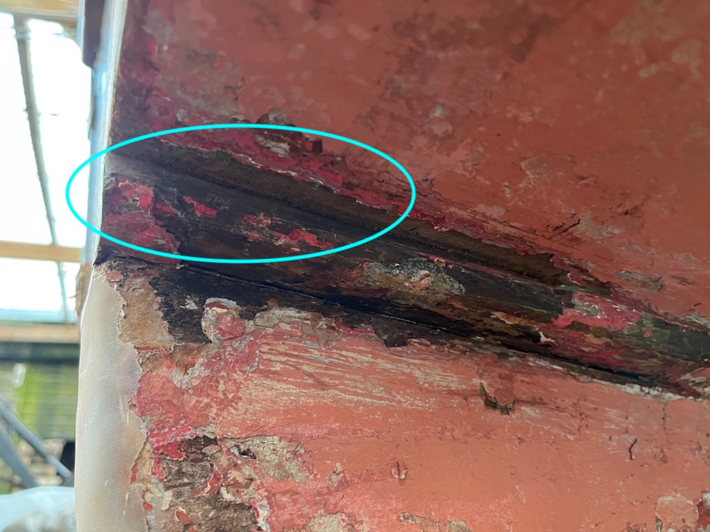
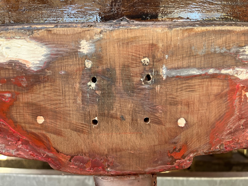
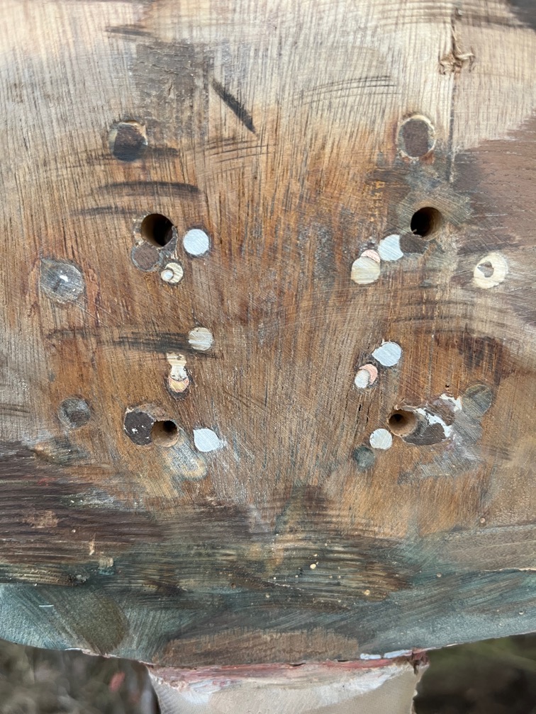
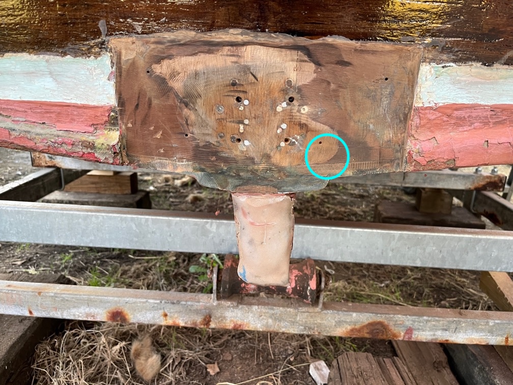
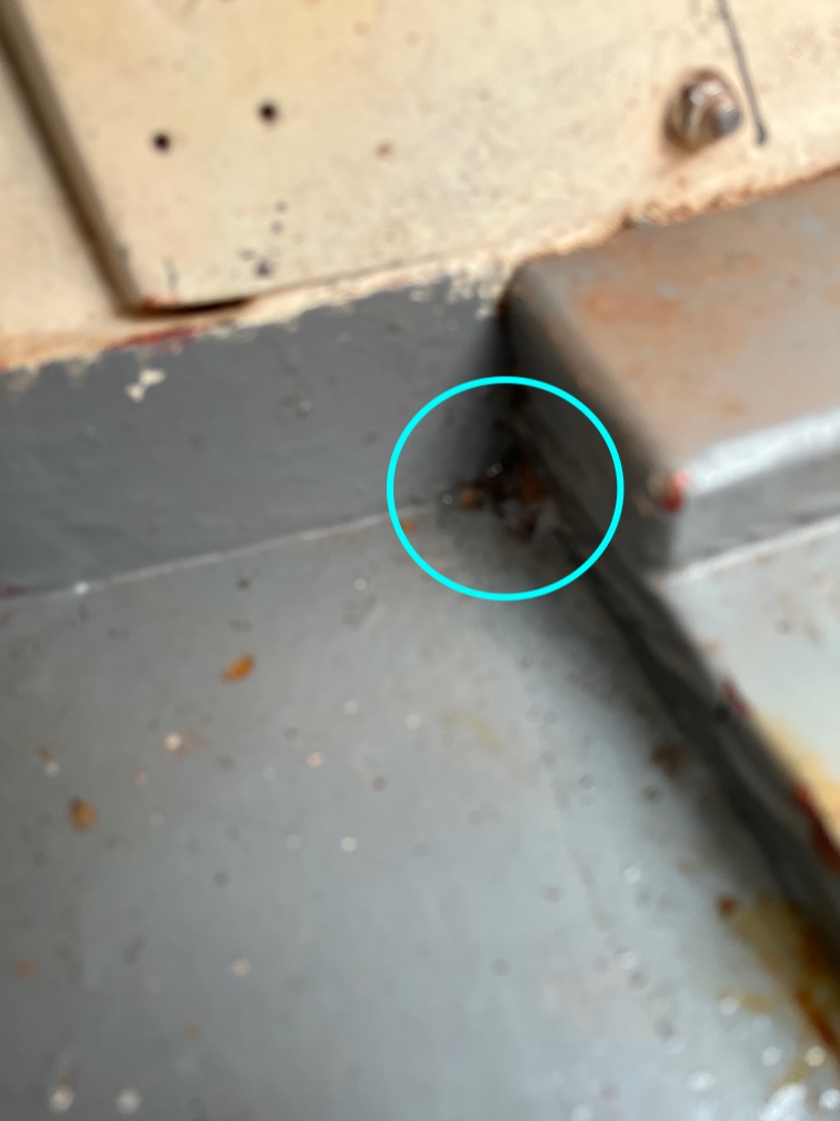
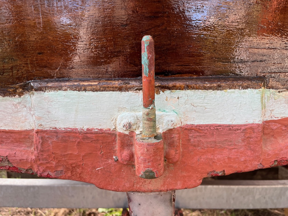
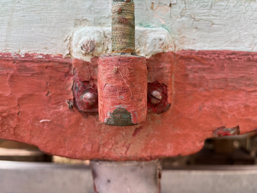
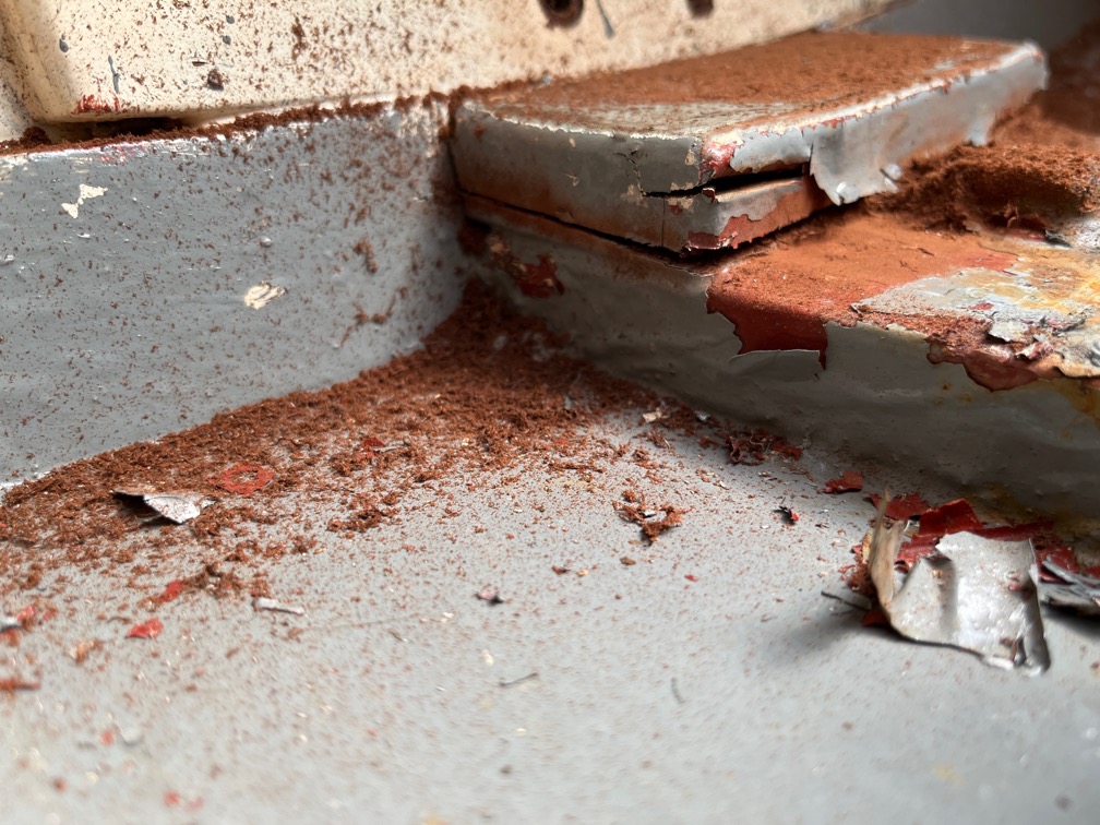
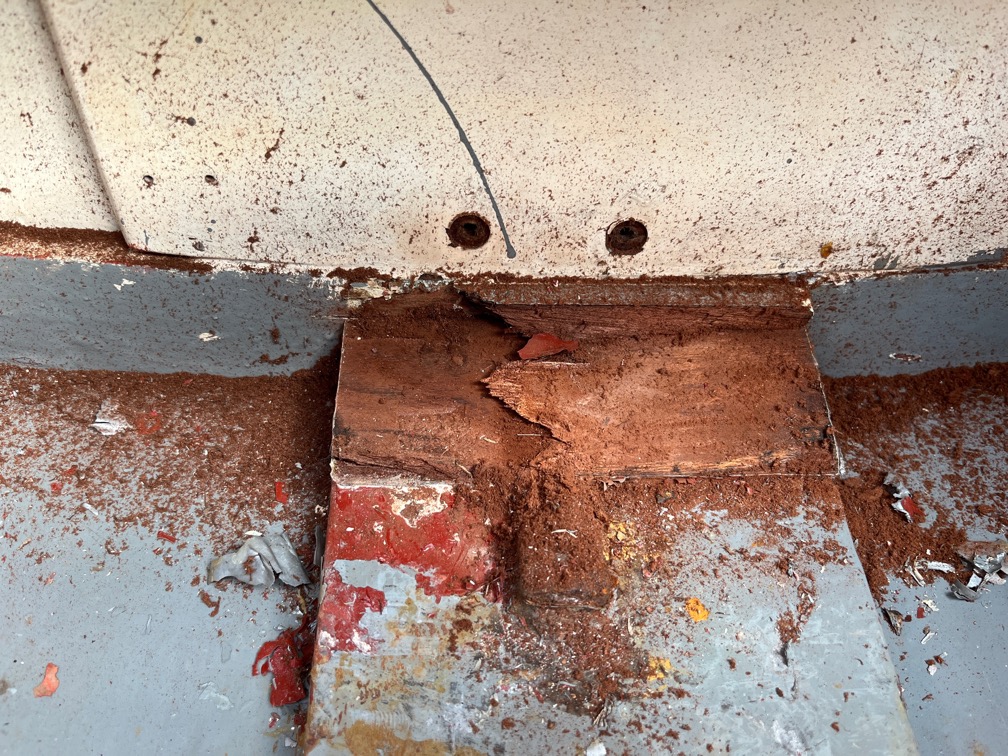
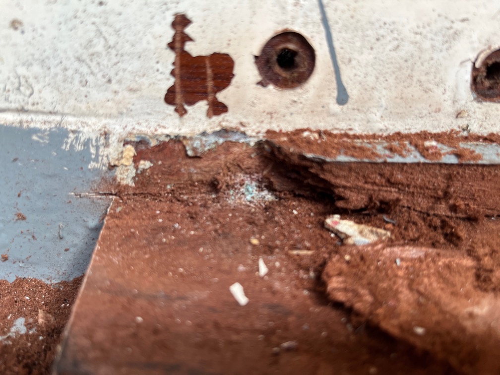
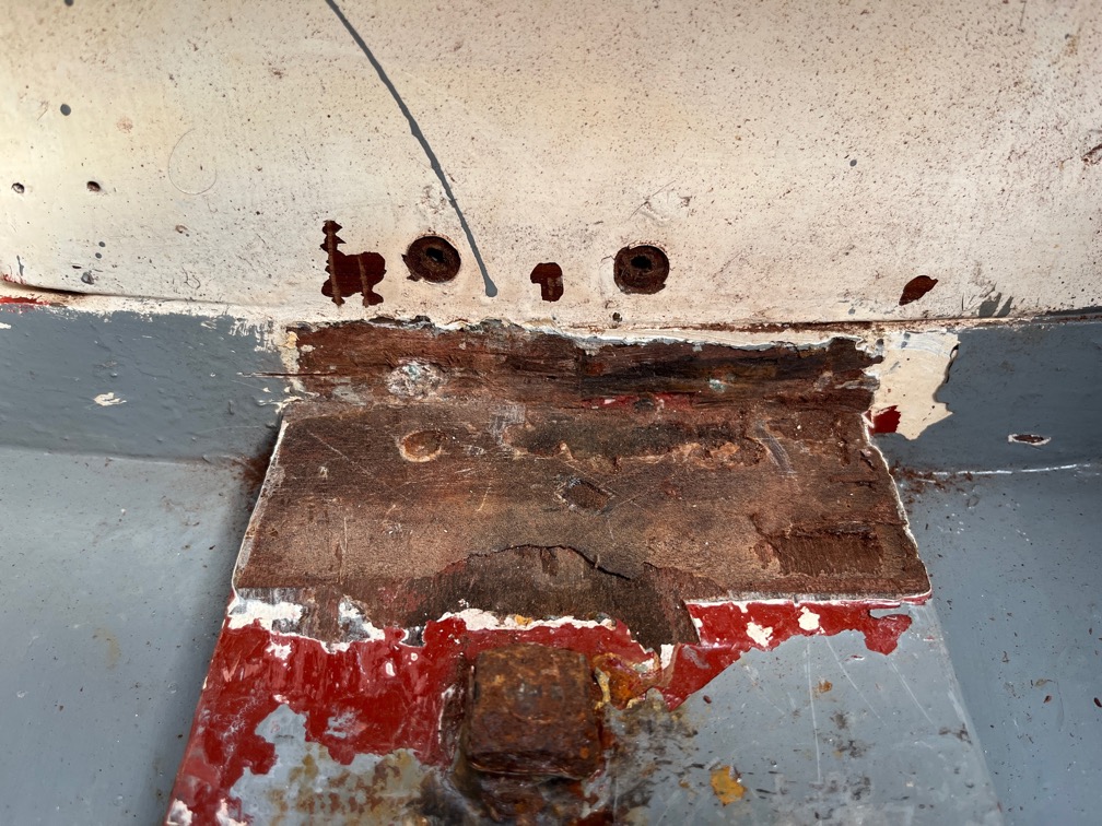
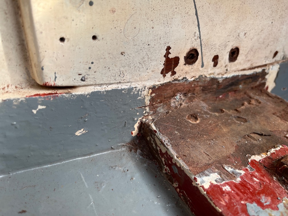
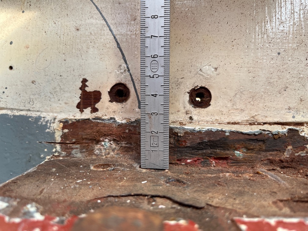
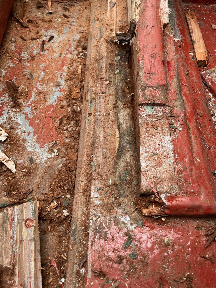
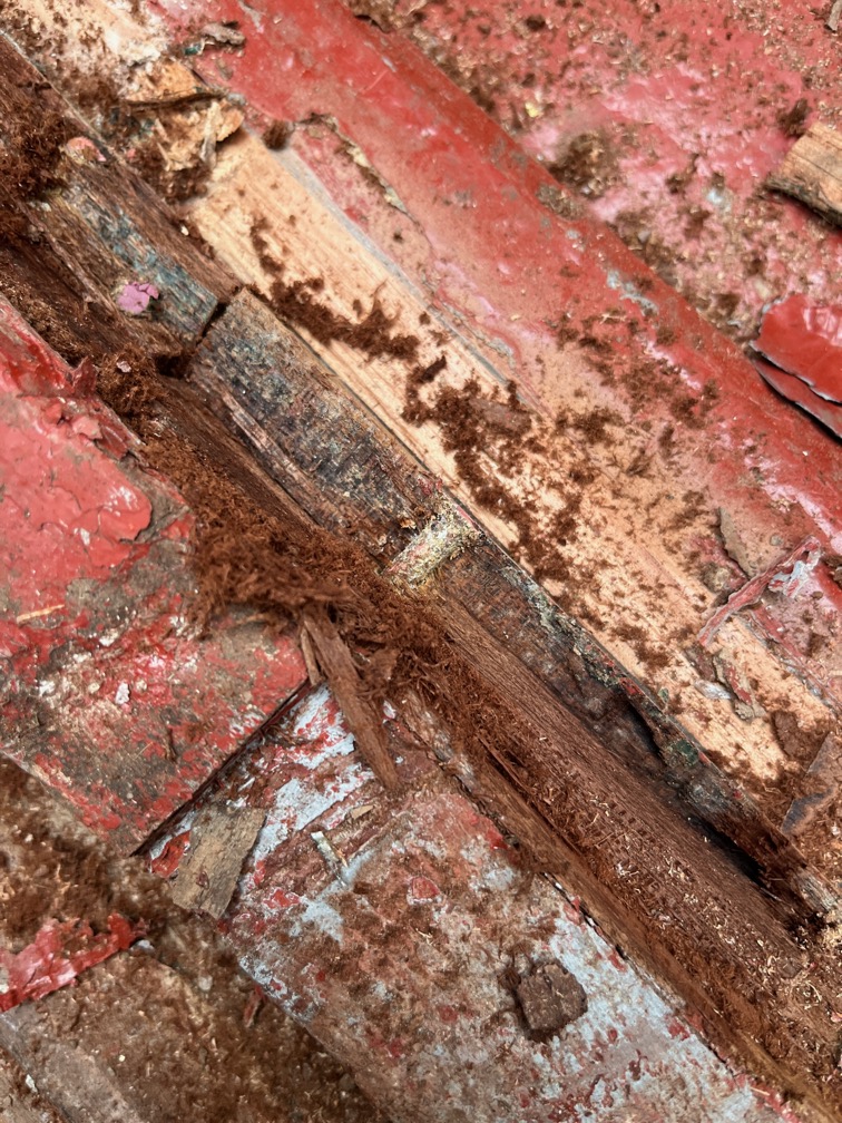
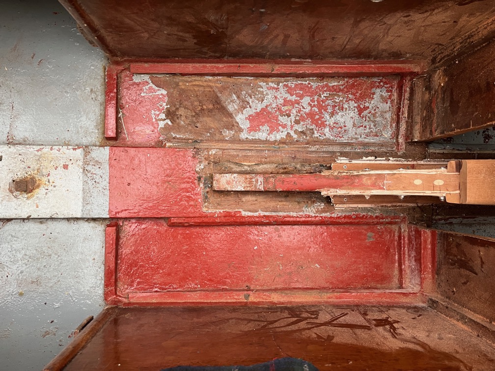
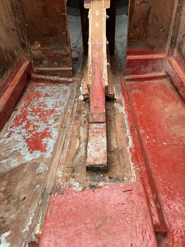
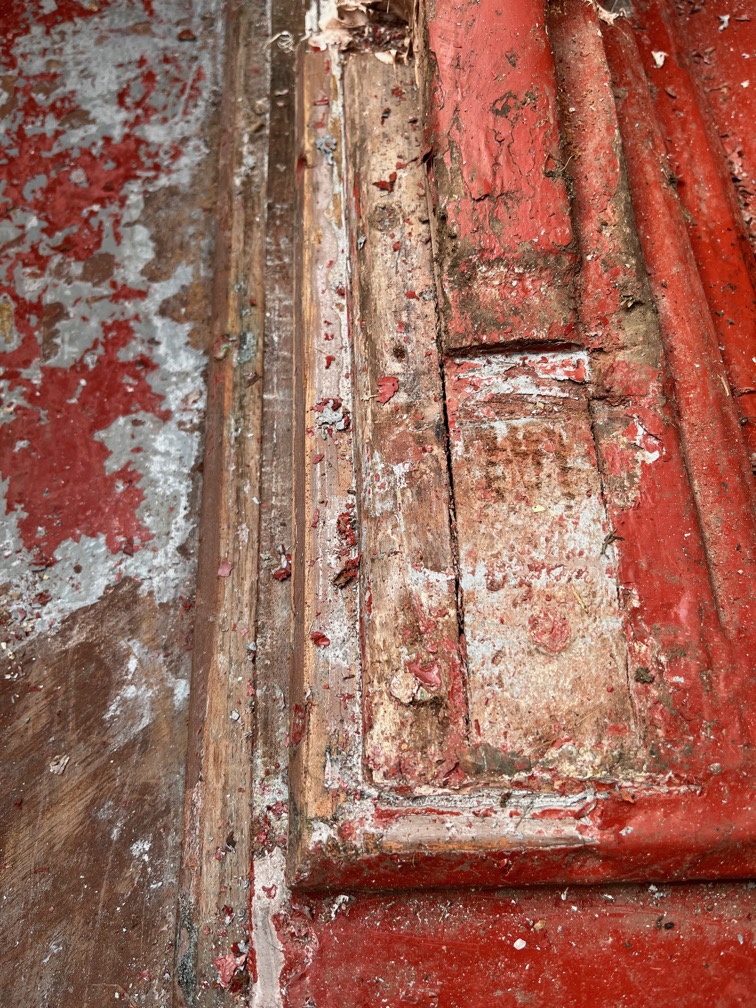
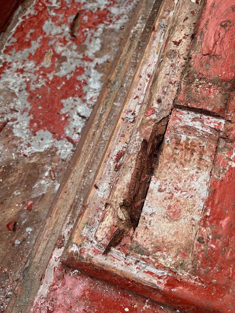
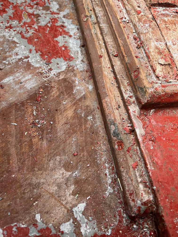
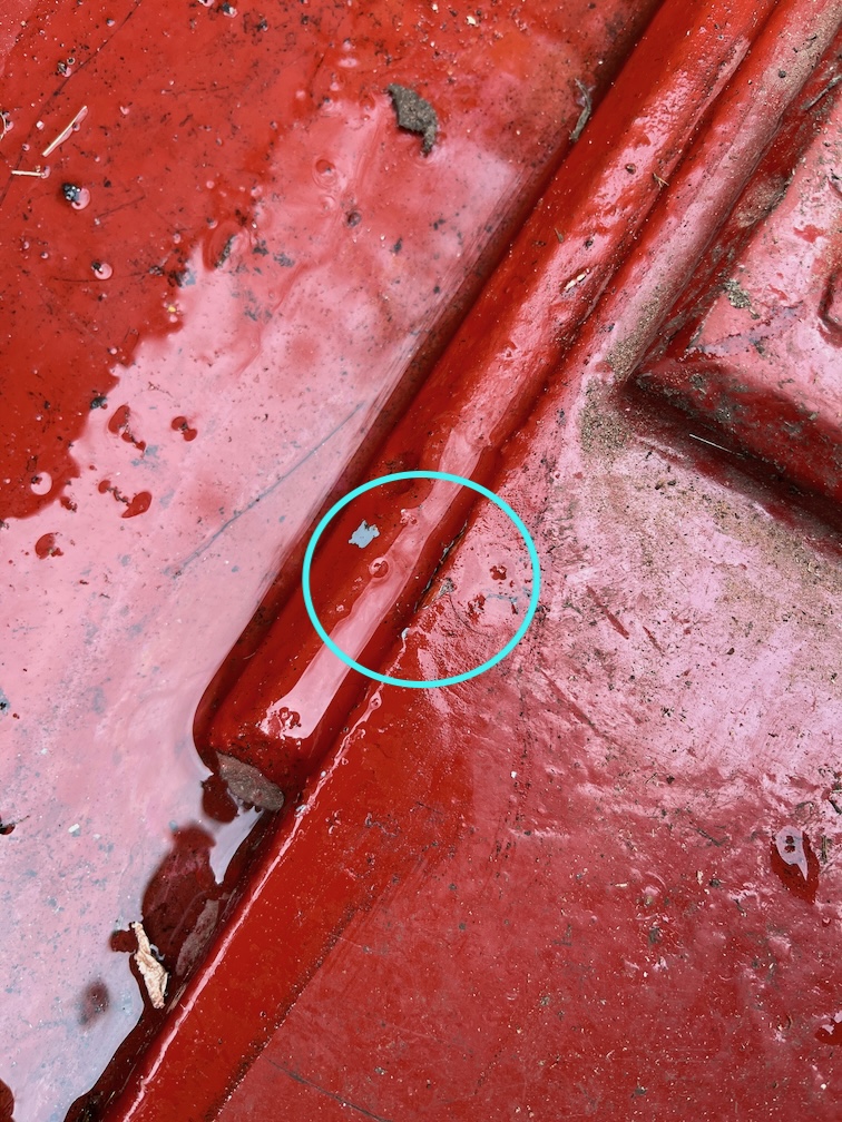
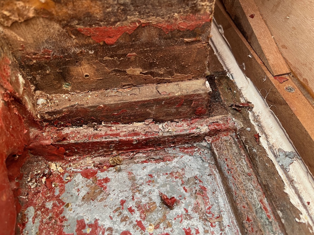
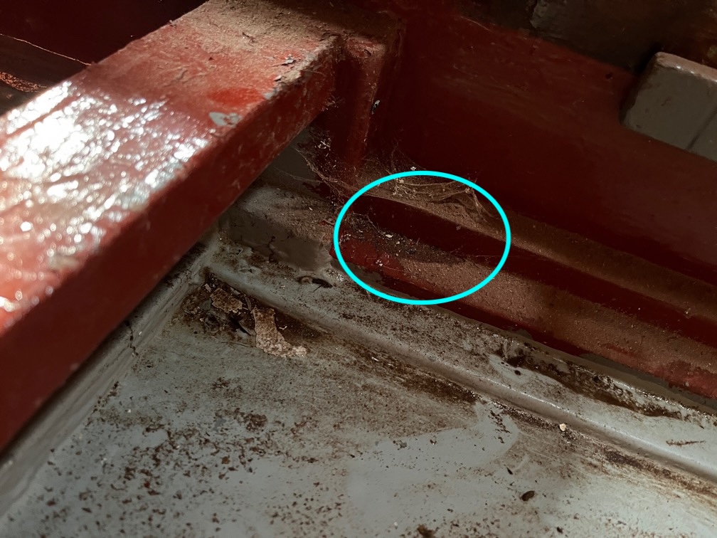
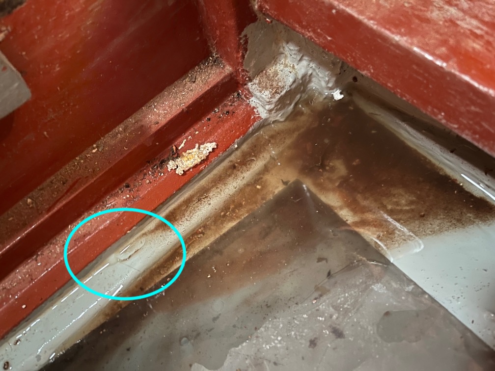
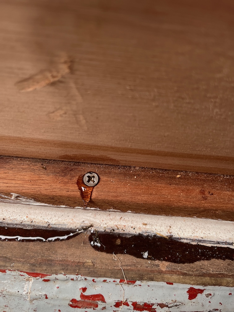
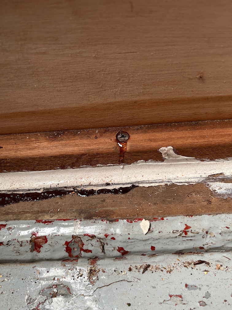
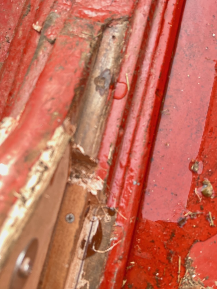
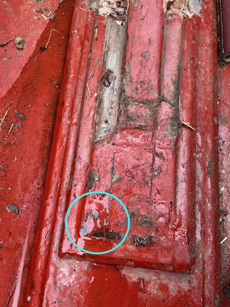
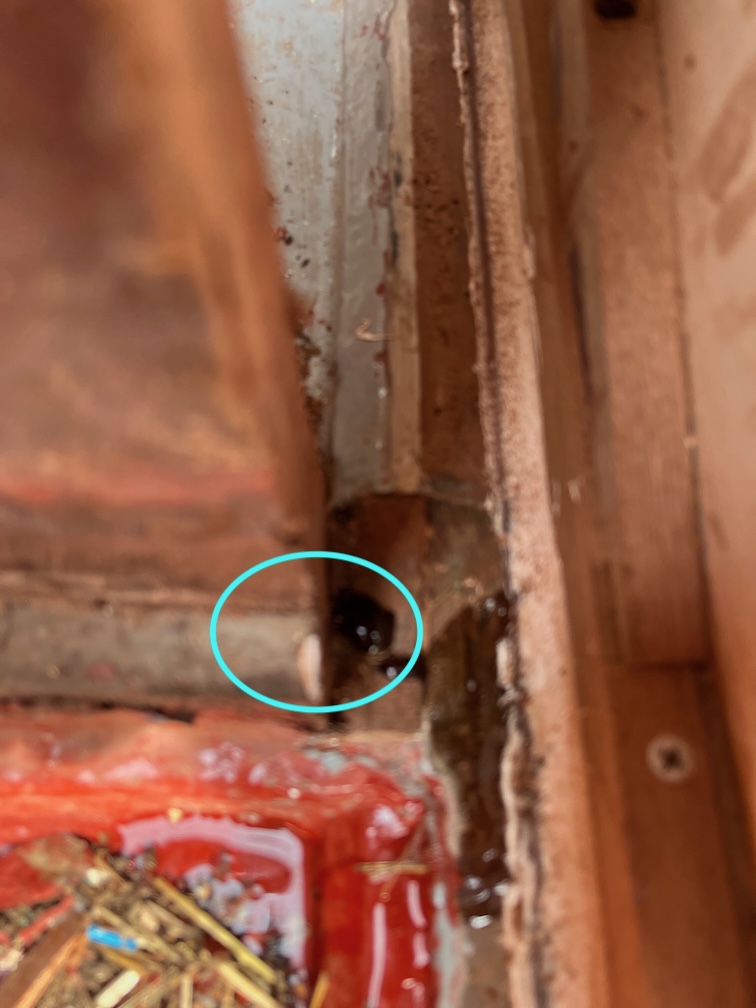
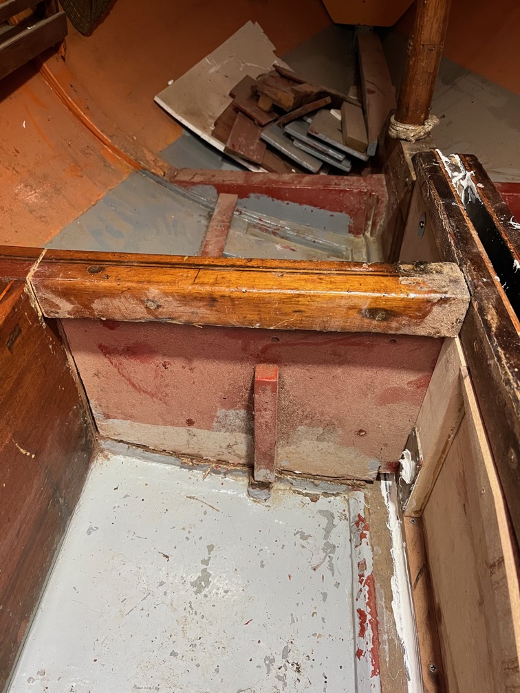
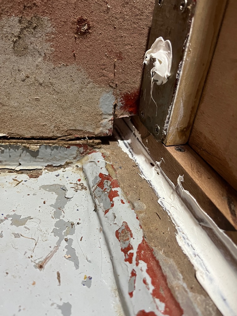
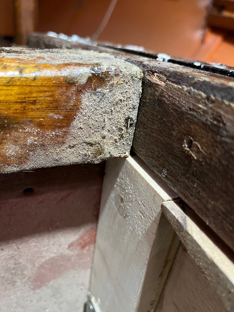
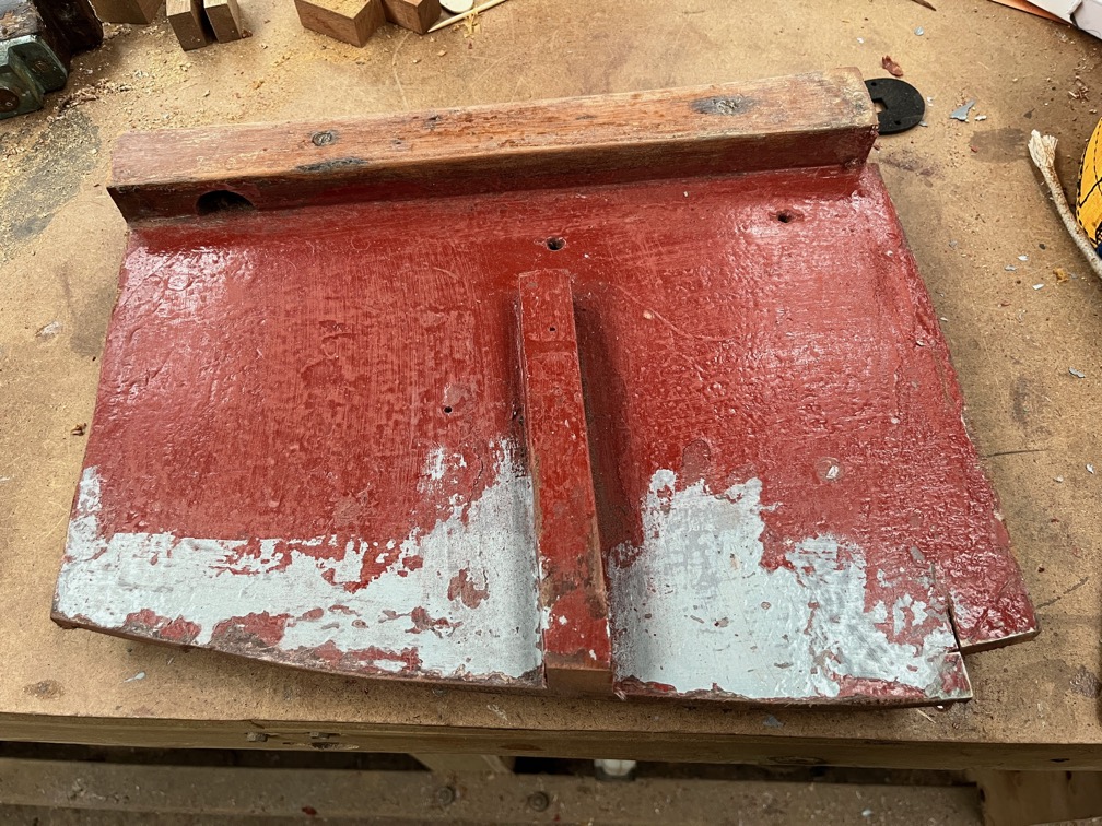
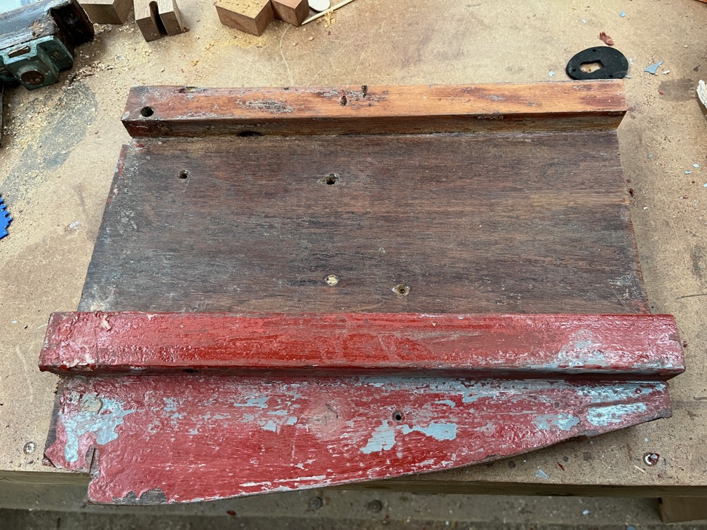
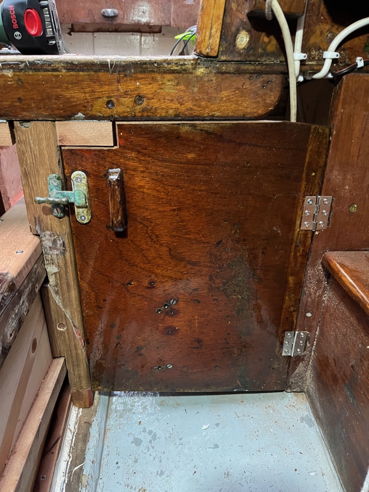
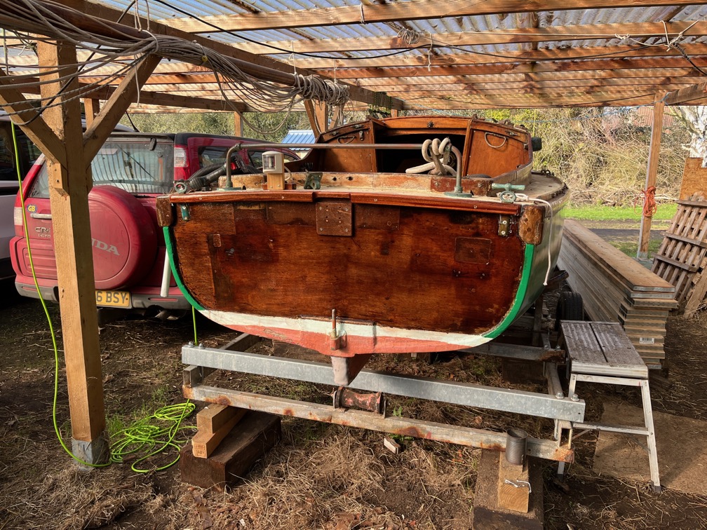
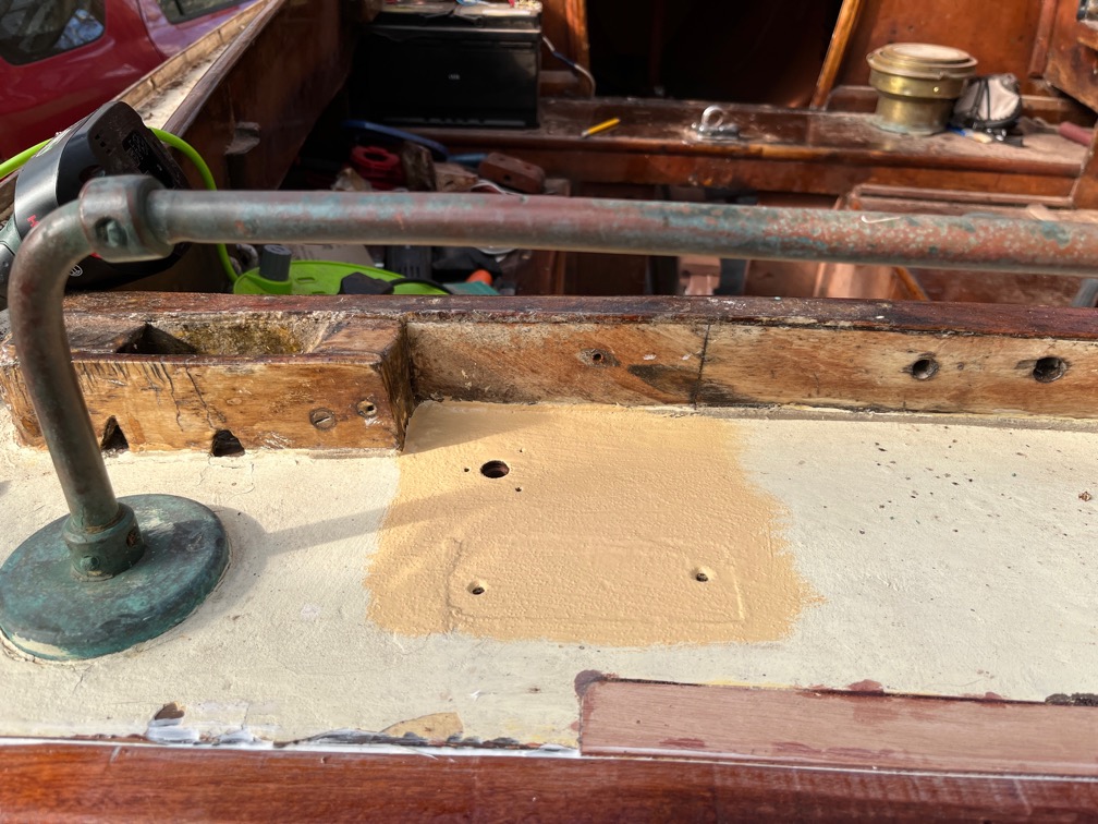
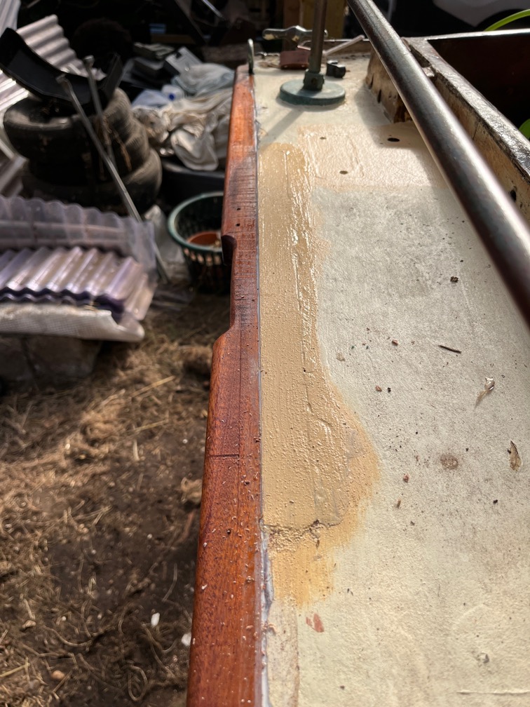
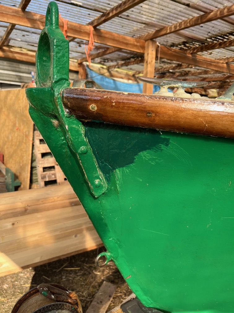
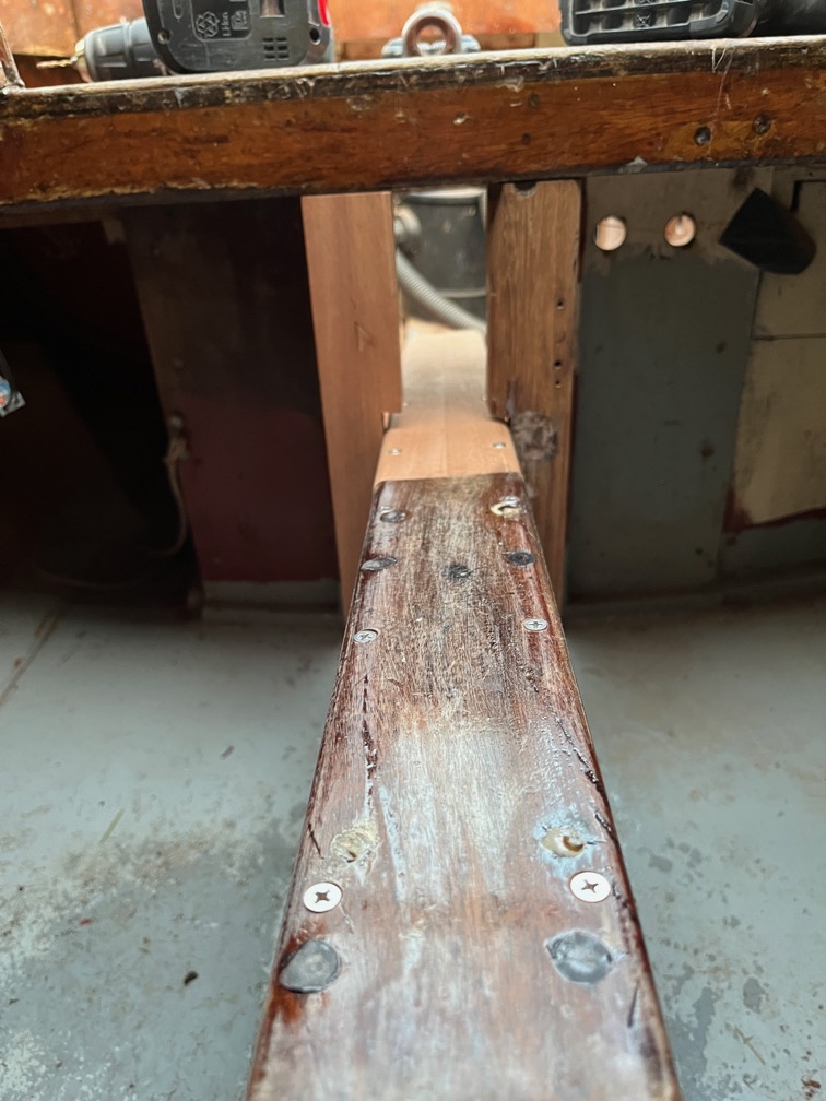
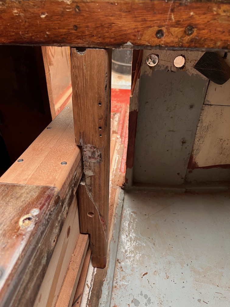
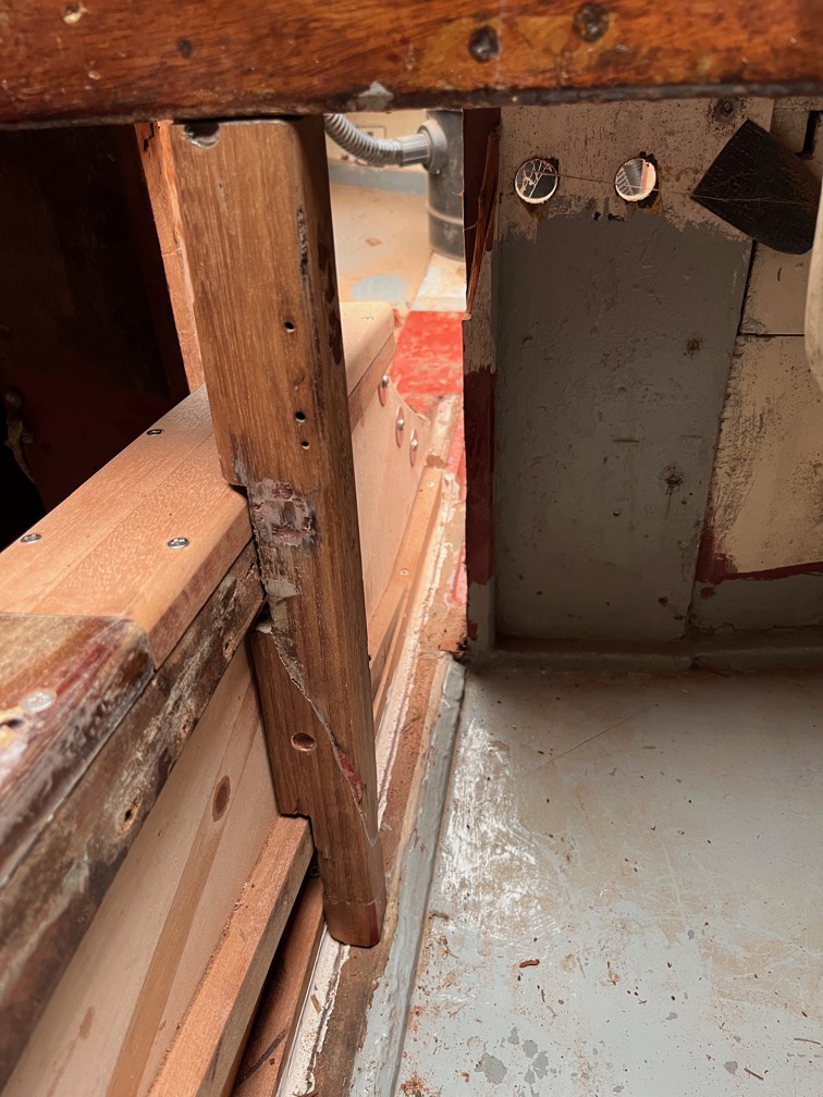
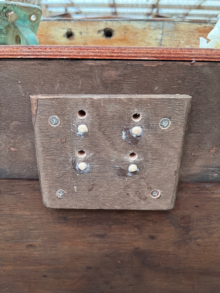
The reason for the change is that having found the crack in the glue line between the hull and the keel at the stern (highlighted above), I am no longer confident about the tightness and strength of the hull. Although I can see the crack here, I do not know its extent. Does it continue forward and this is the only bit that is open to the outside? It is deeper than it appears here?
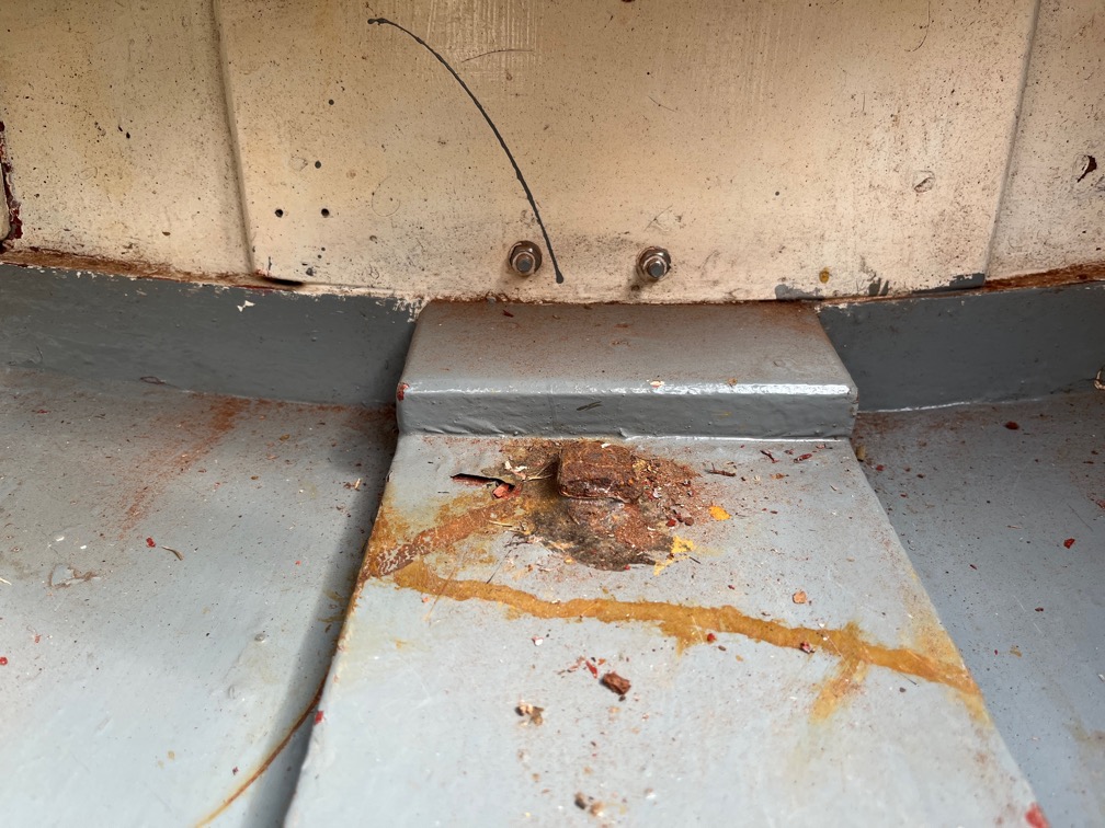
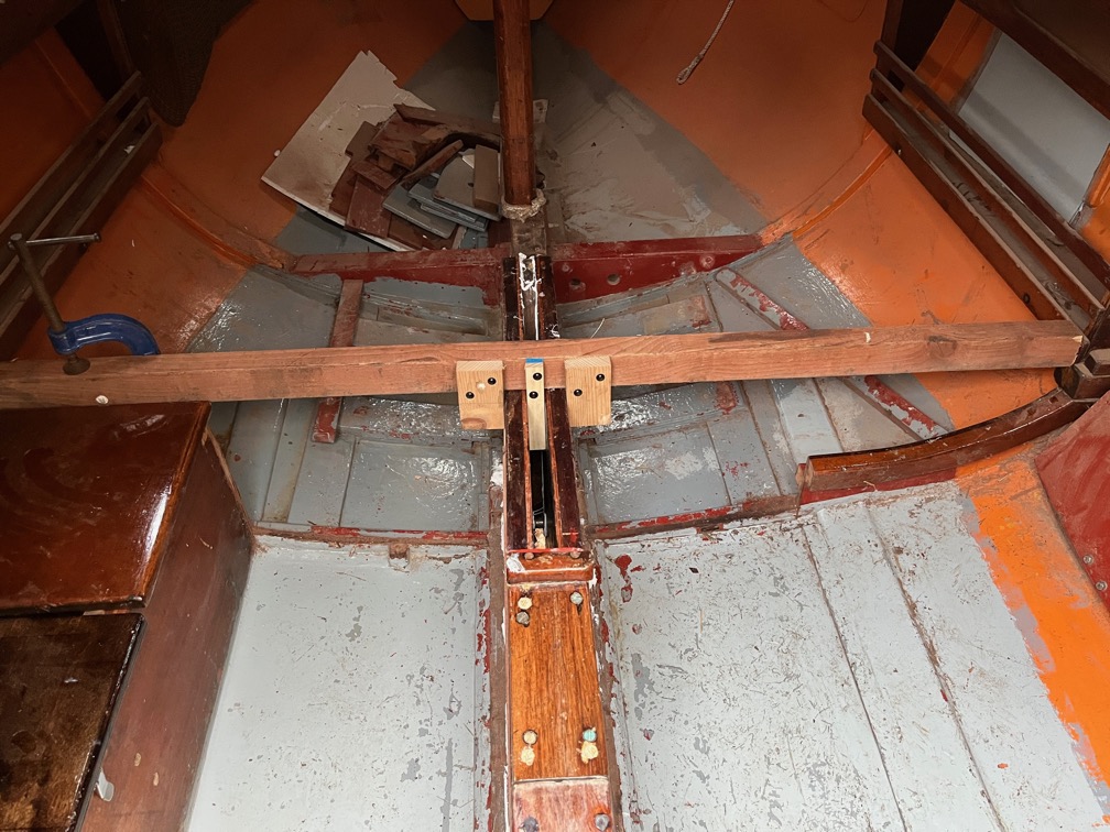
That and the fact that I cannot locate the leak in the hull on the port side that I know is there, just not where it starts.
So, during this season, Shoal Waters will be inverted, the paint and antifouling scrapped off the hull and sanded back to the wood, any dings and scratches filled, the right angle edges smoothed off and then sheathed in epoxy and glass fibre. This will certainly fix the leaks in the bottom and also provide a great deal of additional strength to the hull. Then she will be repainted ready to be launched next season whilst Naiad is brought ashore to have her maintenance done.
After that, we shall see what happens.
So, for now the plan is to get Naiad ready to launch and then invert Shoal Waters and make a start on her sheathing. As a side note, Naiad’s hull was sheathed more than thirty years ago by her previous owner and has not suffered leaks of loss of strength as a result, so this is not an unusual thing to be doing.
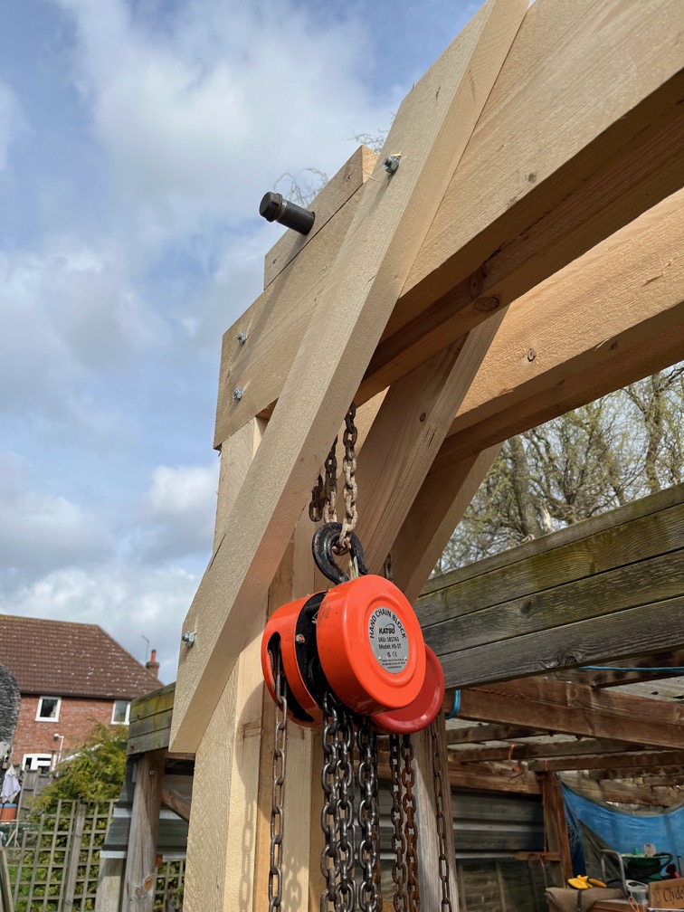
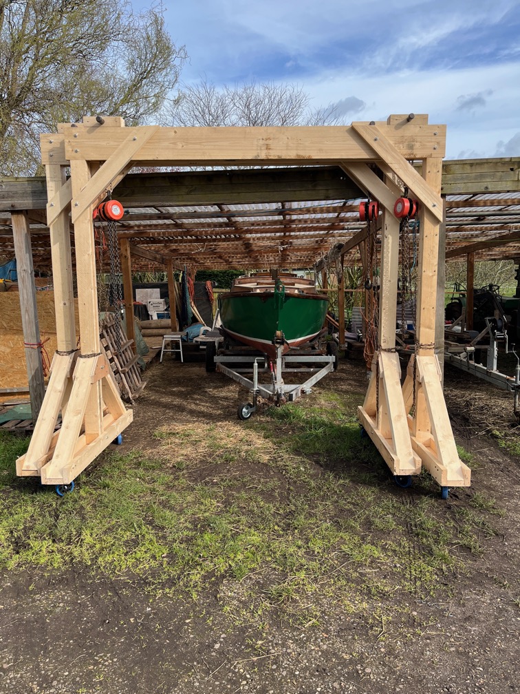
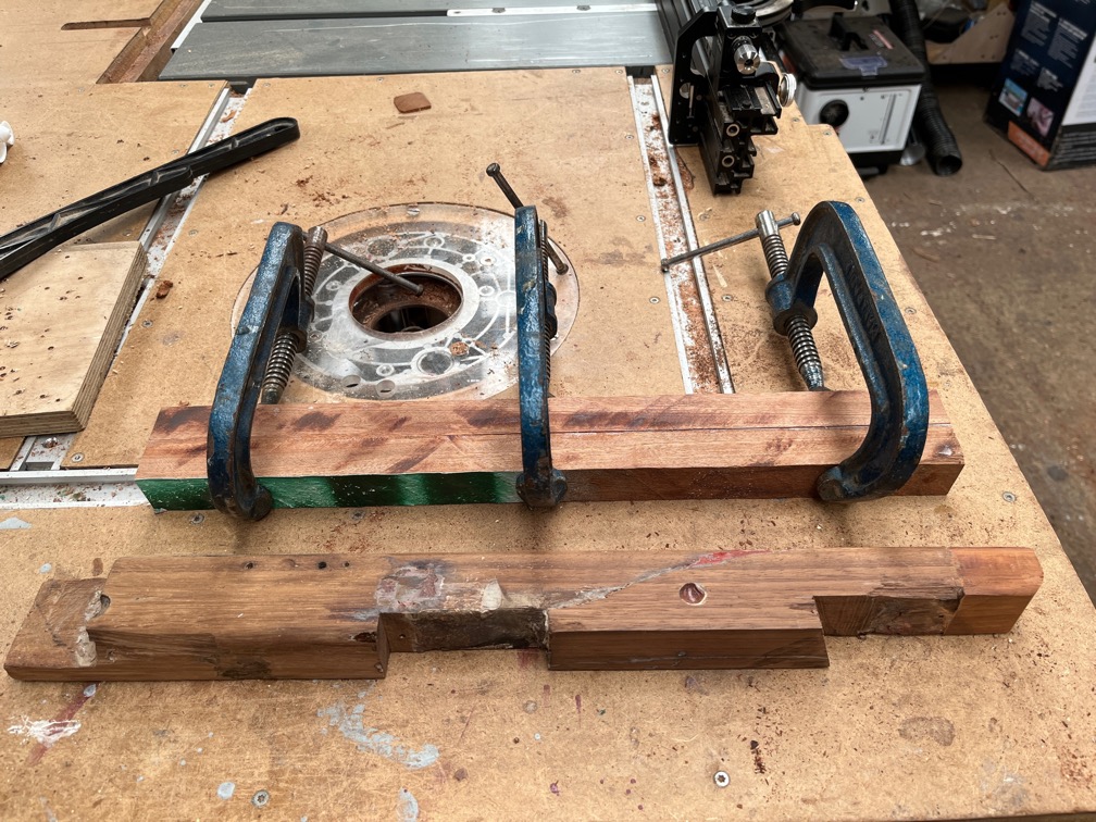
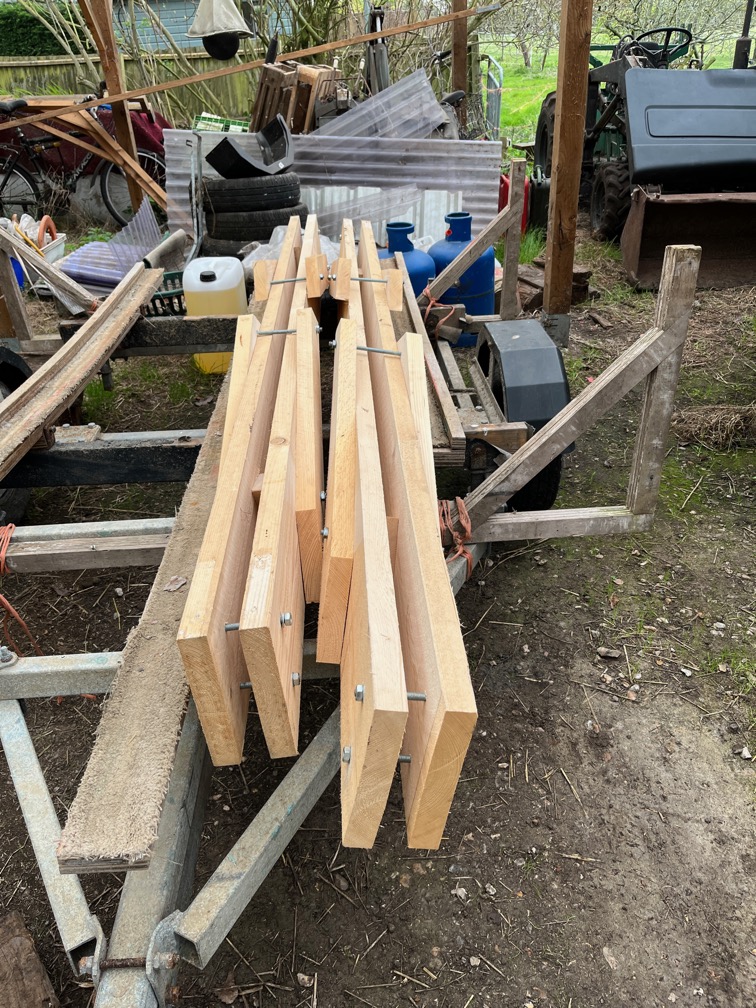
The launch of Naiad and the inversion of Shoal Waters will require the use of the gantry cranes and these need to be coated in preservative before that hapens.
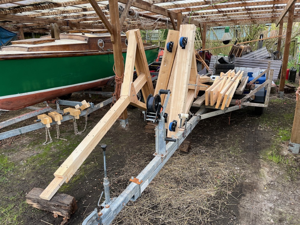
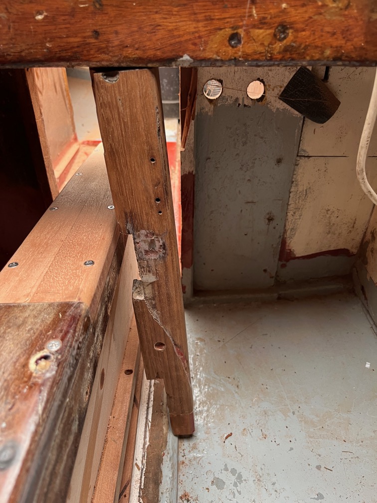
Recently the legs and gantries were taken apart and stowed in the hay barn out of the weather. The legs are sufficiently tight in the feet as to require two people and a crowbar to remove, so that had to be fixed before the coating.
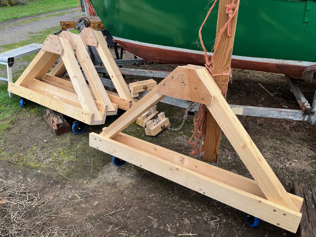
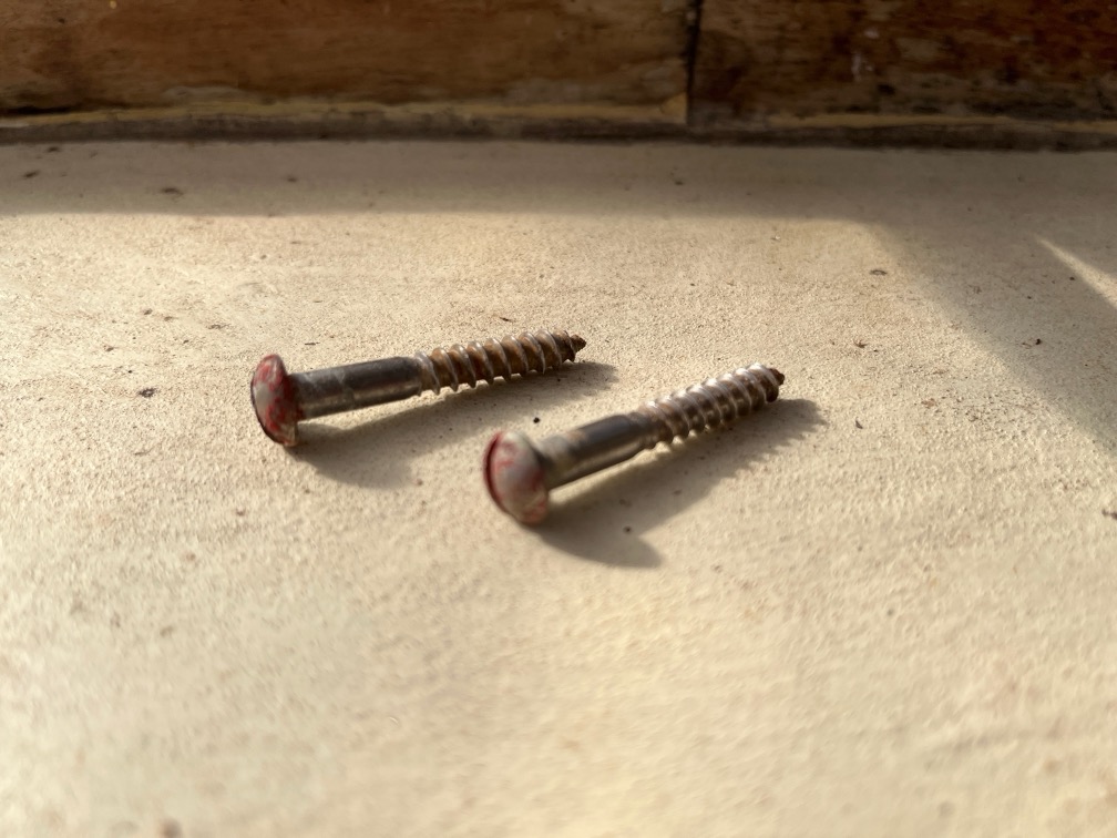
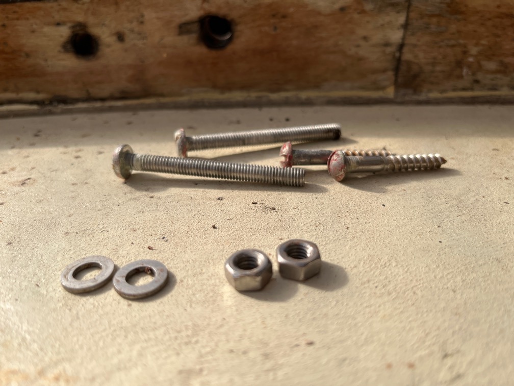
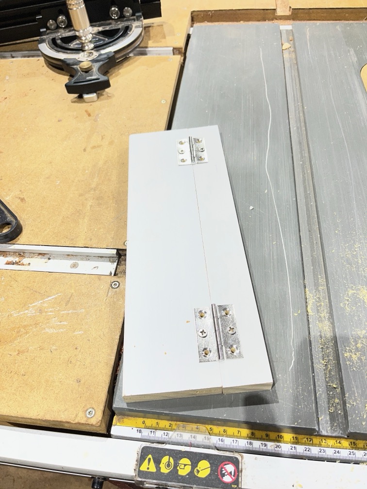
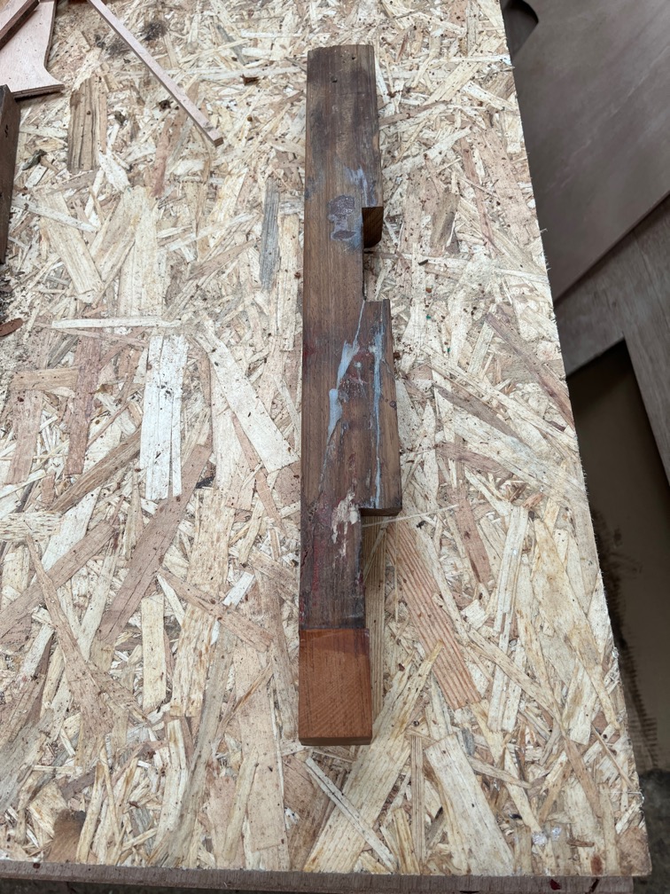
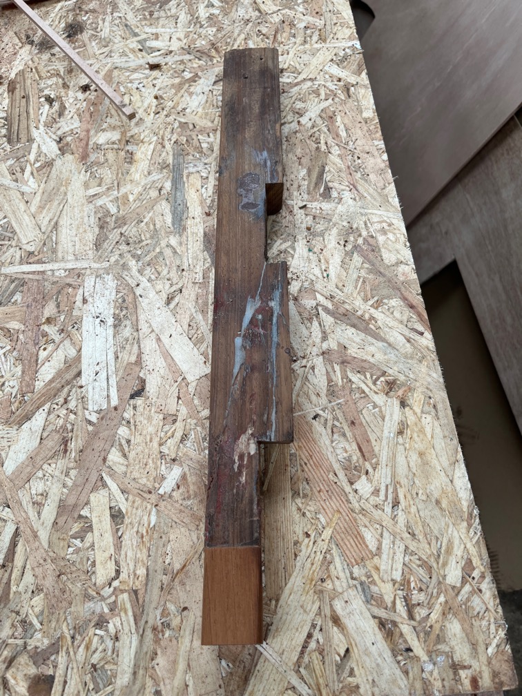
All the bolt holes also needed to be opened out to 13mm as the wood had expanded due to the moisture in the air and the bolts, although a loose(ish) fit originally, had become a tight fit requiring the use of a hammer and drift to get them out. The feet and legs were separated…
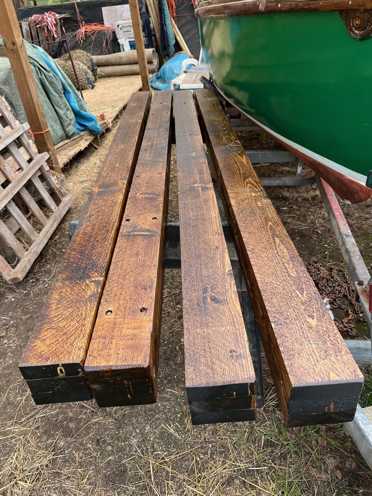
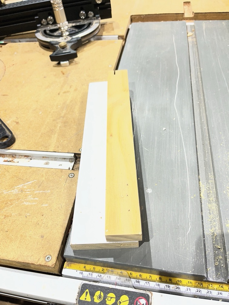
… a thin layer of wood sanded off the lower part of the legs to make them less of a tight fit in the feet and then coated with a replacement for the creosote that we used to use but is now banned. Shame, since the alternatives are not as good.
The cross beams have yet to be taken apart as space is limited. They will be treated once the legs and feet are done.
Once the cranes have been coated and reassembled, Naiad will lifted up off the blocks so that I can scrape the hull.
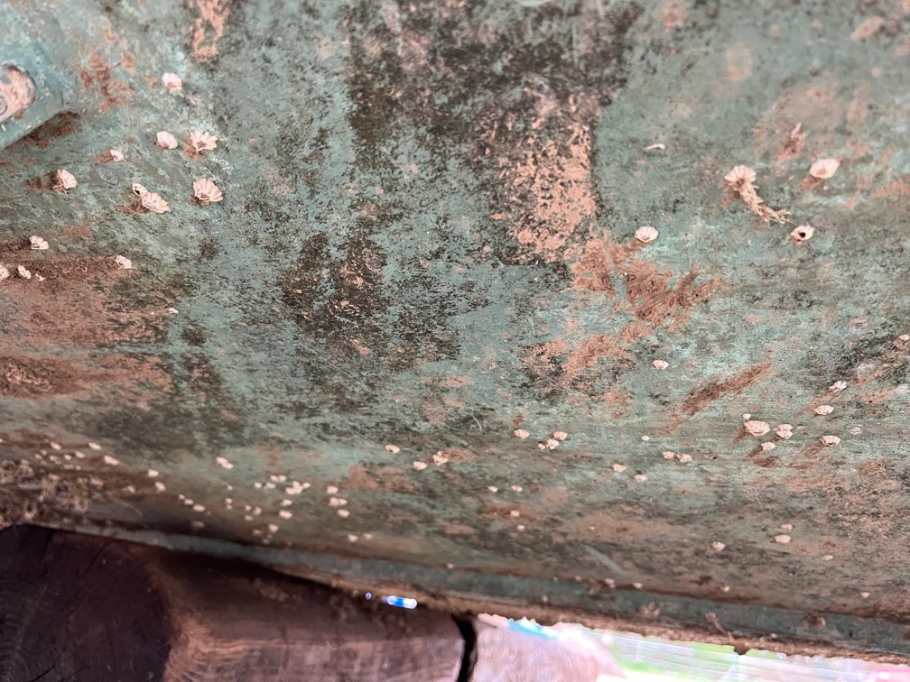
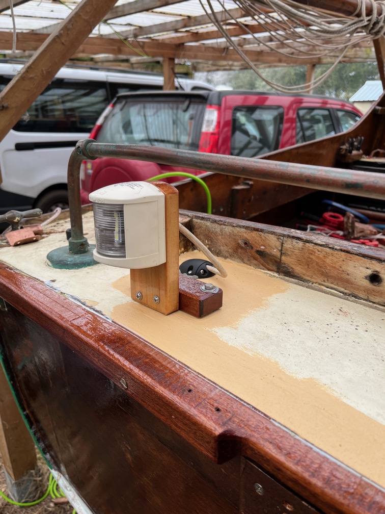
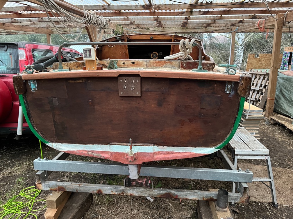
This is what she looks like right now with a fair number of dead barnacles as well as the dried mud I was not able to get off when she was on the travelling trailer.
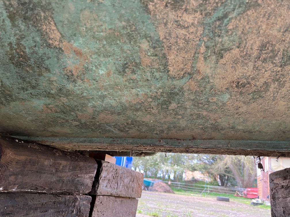
This is after a couple of minutes work with a scraper. The dried mud and dead barnacles come off very easily.
Then Naiad will be put onto the travelling trailer and Shoal Waters moved to the hard standing and inverted. I can’t put her into the har barn inverted as the cranes are too high for that and the working trailer is not set up for an inverted boat.
Instead, I’ll use the cranes to support a plastic tarpaulin as a temporary working space whilst the hull work is done.
Unless I can figure out a way to get Shoal Waters onto the working trailer inverted.
Time for a cup of tea.