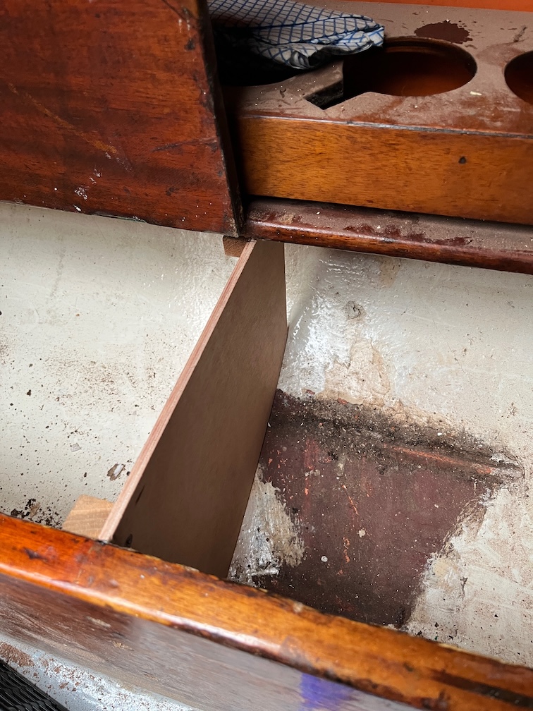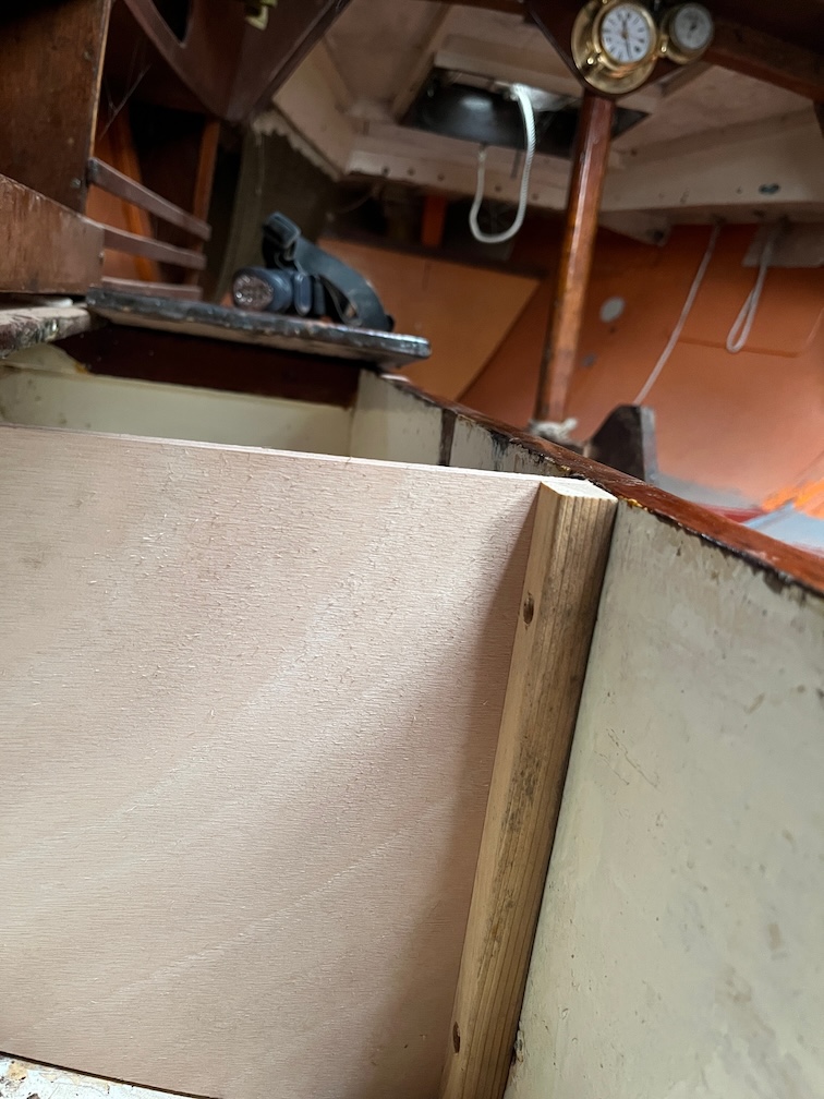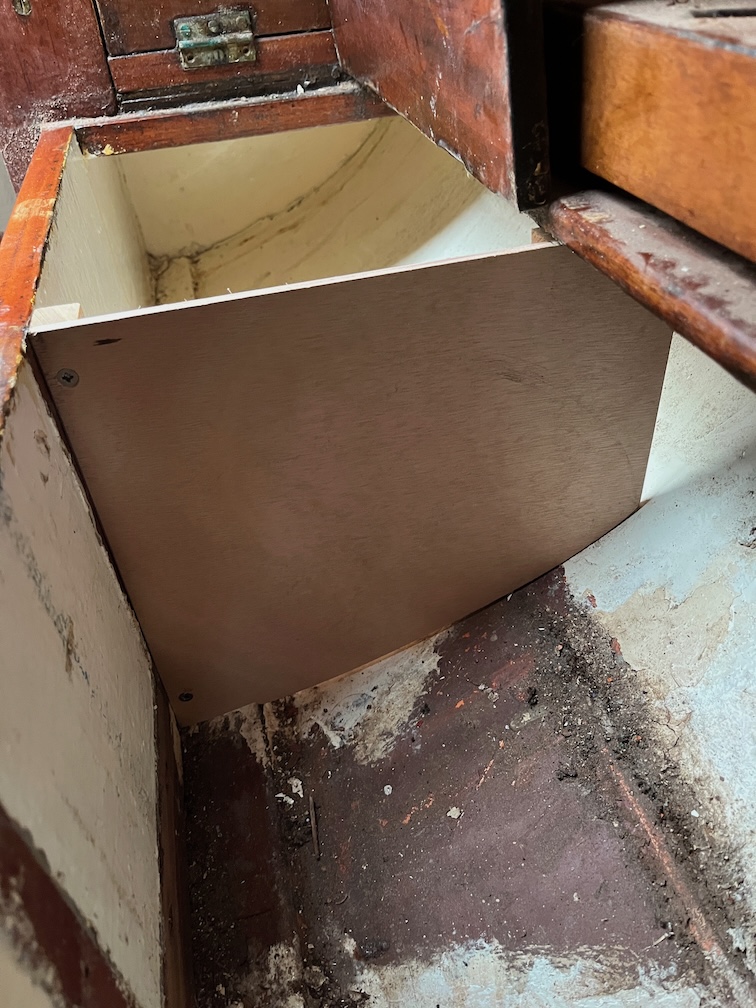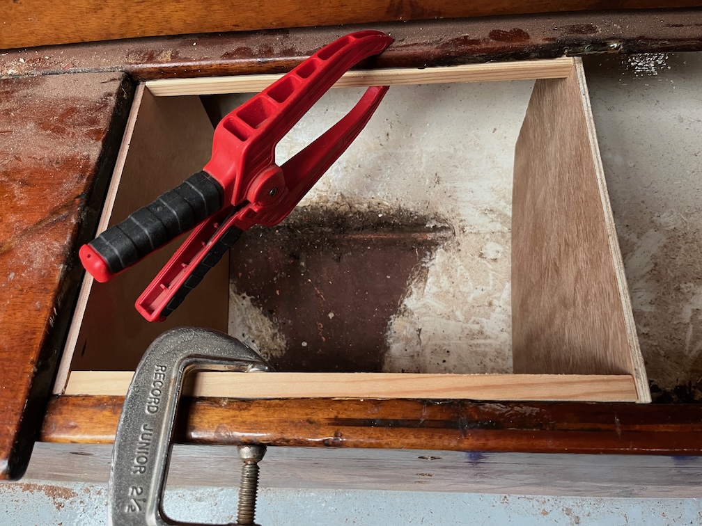
As is now usual the first task before work was to apply some varnish to two small areas in the boat, the back of the new galley locker and the cut side of the forward locker lid.
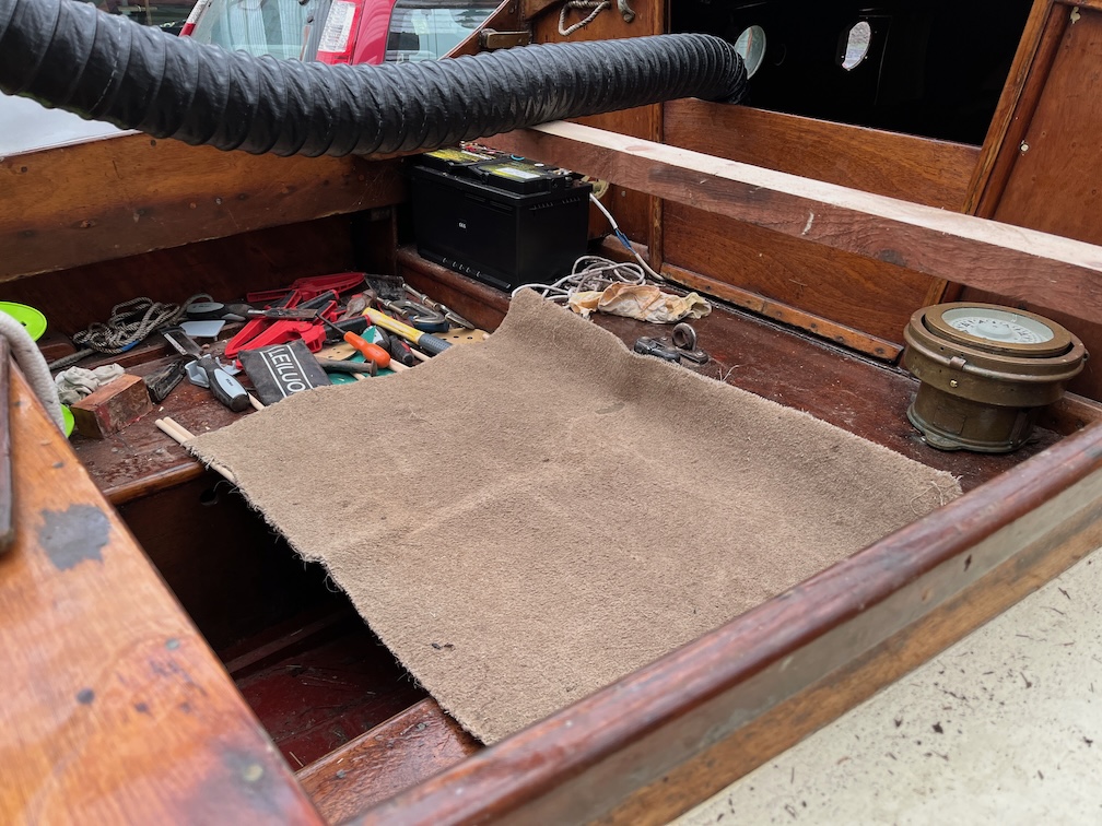
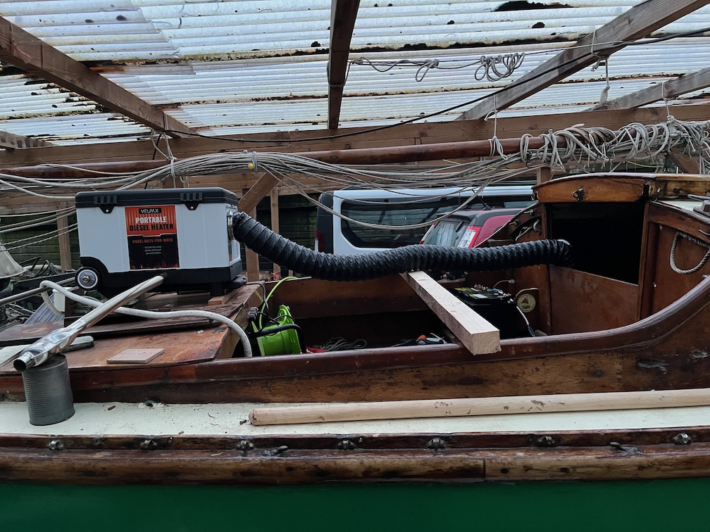
After that I turned the heater on, pointed the end of the hot air duct towards the existing aft block, covered the cockpit footwell with a piece of carpet and left it running for a couple of hours.
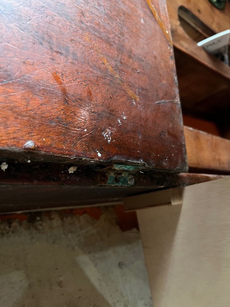
During my morning tea-break I applied neat epoxy to the top of the aft block, now well warmed up, and to the bottom of the new piece, also warmed up by being on the Rayburn all night, then added some thickener to the remaining epoxy, spread some of this onto the bottom of the new piece, and took thickened epoxy, top and pins down to the boat.
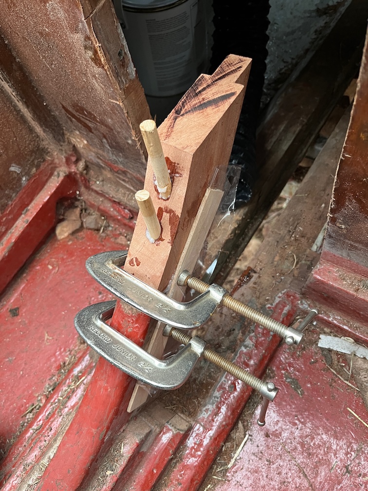
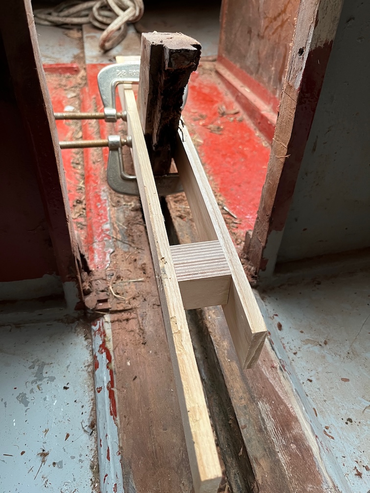
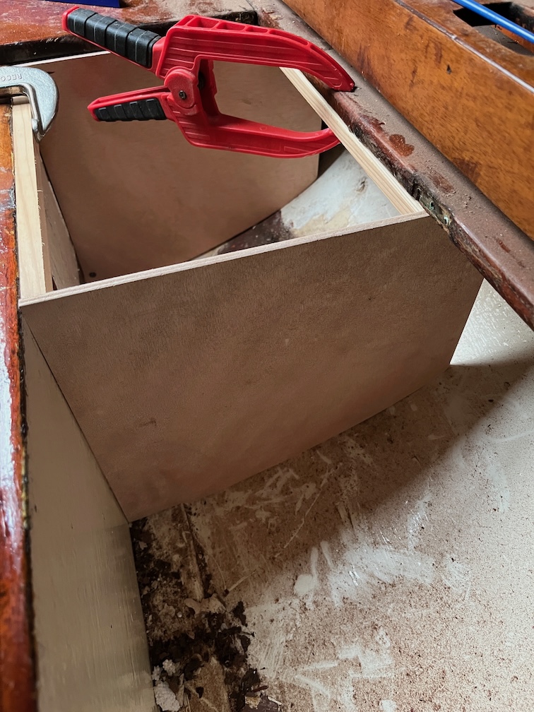
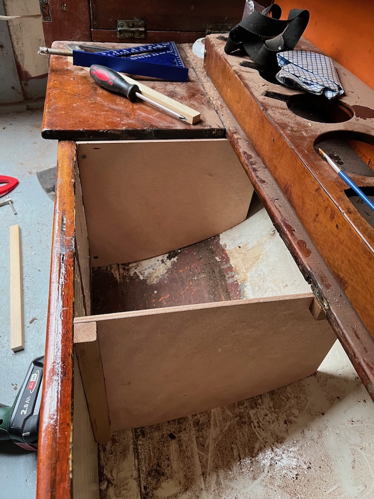
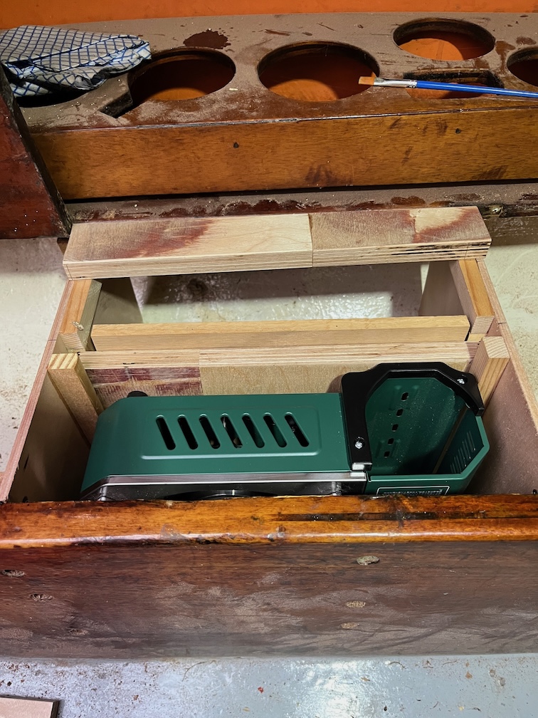
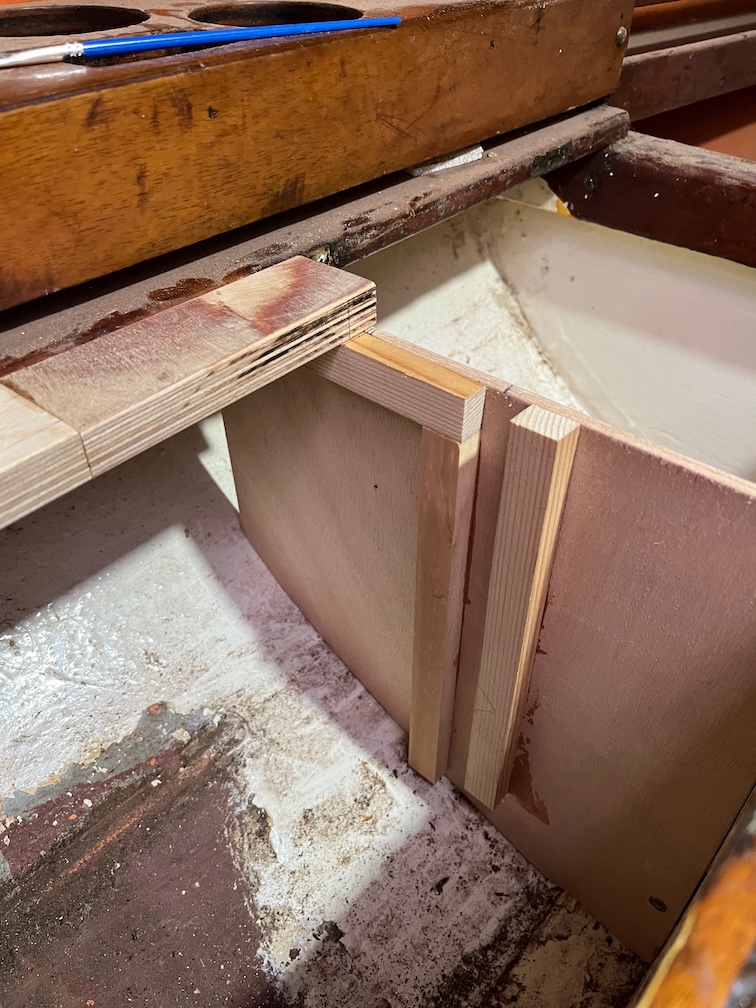
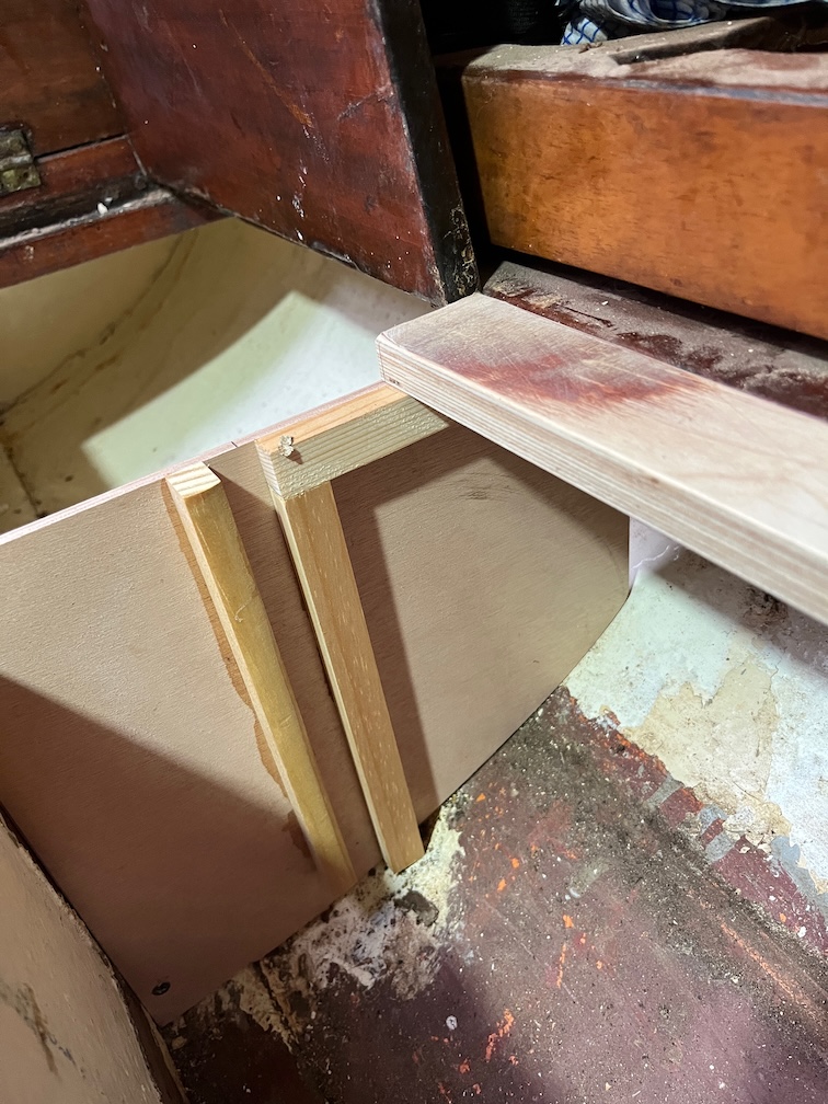
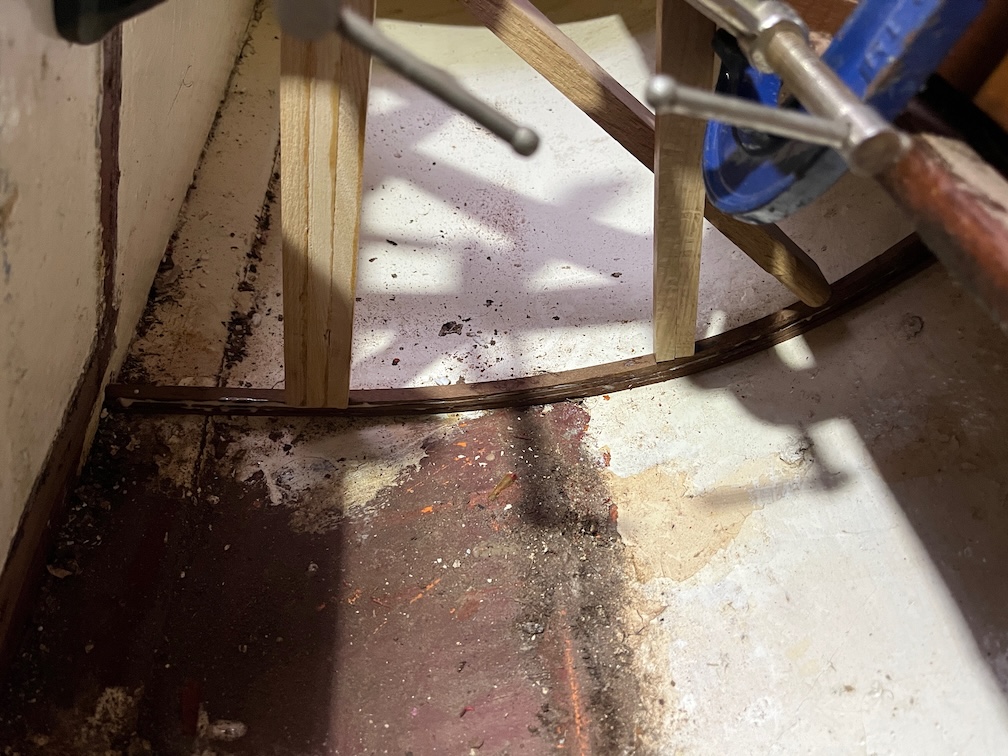
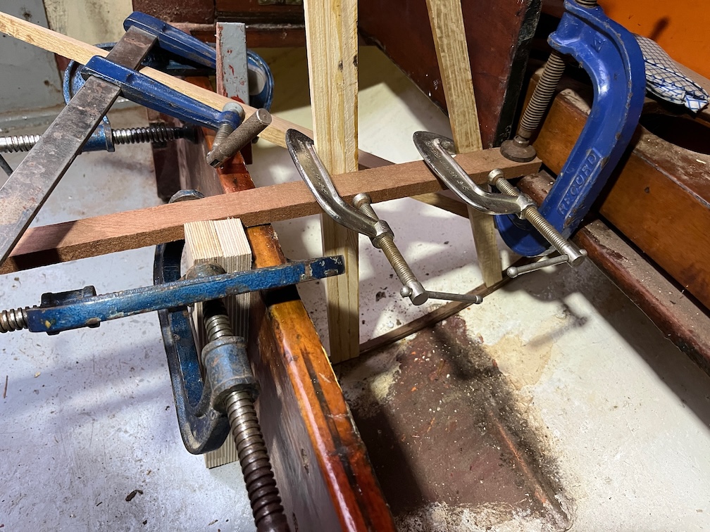
The pins were put into the top section and allowed to protrude an inch or so to make locating the top easier. The new section was put in position and the pins tapped into their holes fully. After a little cleanup of the squeezed out epoxy I clamped two thin pieces of wood on either side of the block, each having plastic film wrapped around them as I do not want them to stick to the block. After that I replaced the carpet over the footwell and hopefully, even on its lowest setting, it will be enough to keep the wood and epoxy warm enough to cure properly.
I’ll leave the heater running for most of the day and then evening to give the epoxy time enough to begin the cure process.
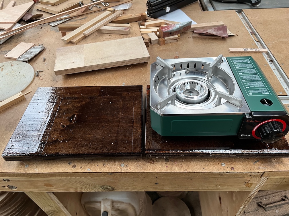
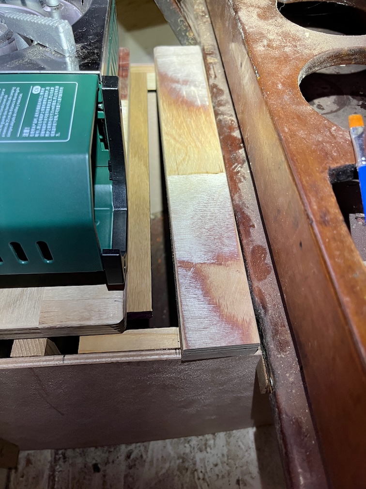
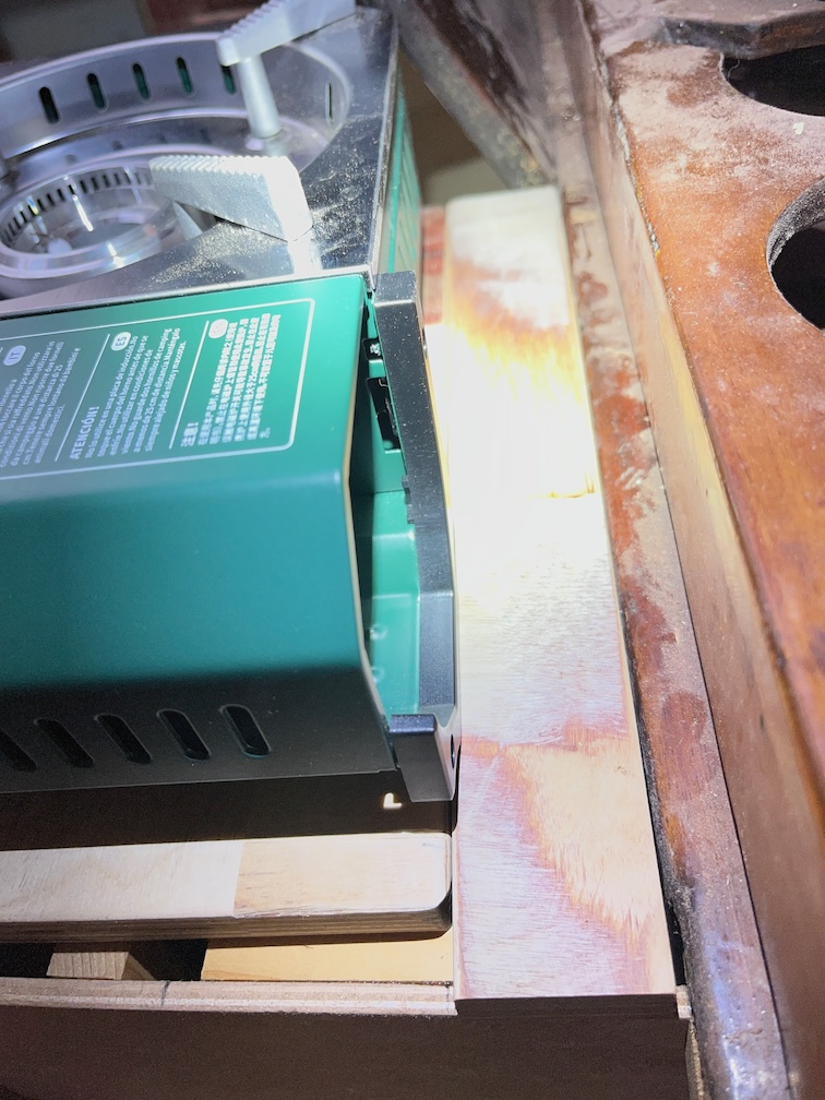
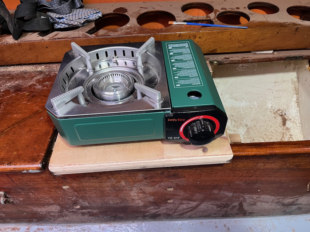
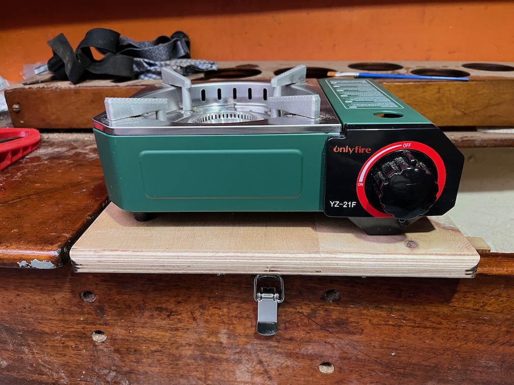
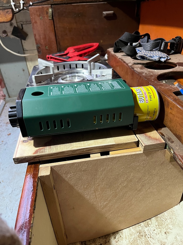
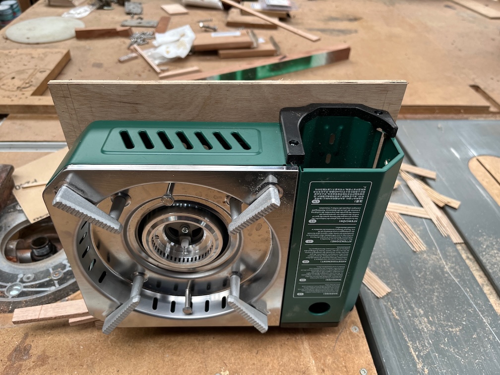
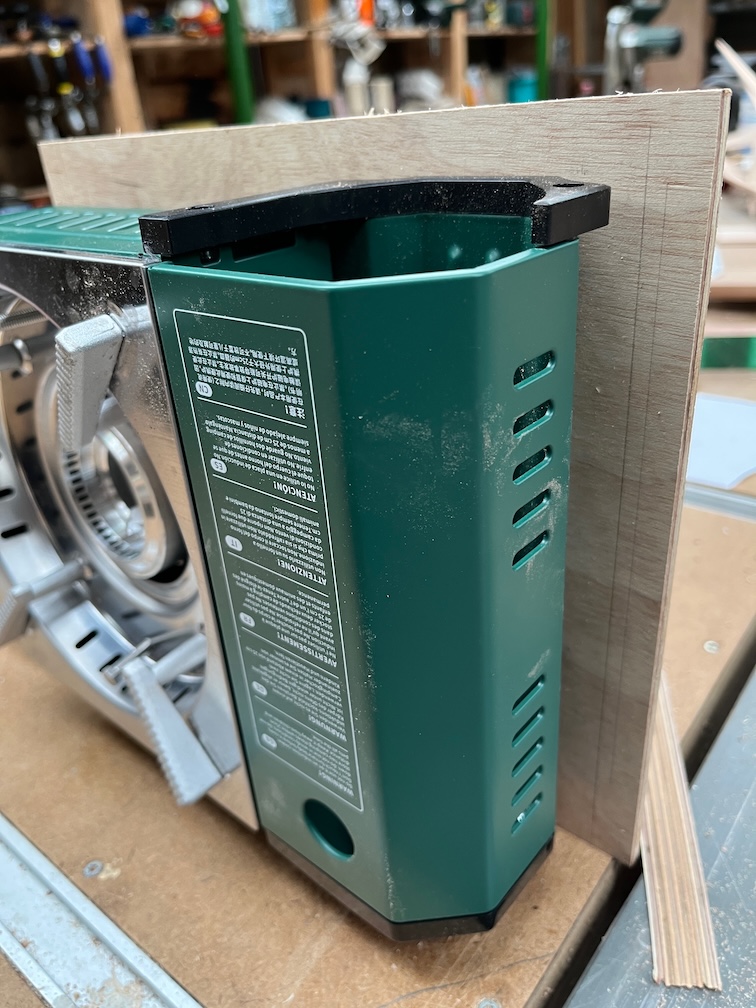
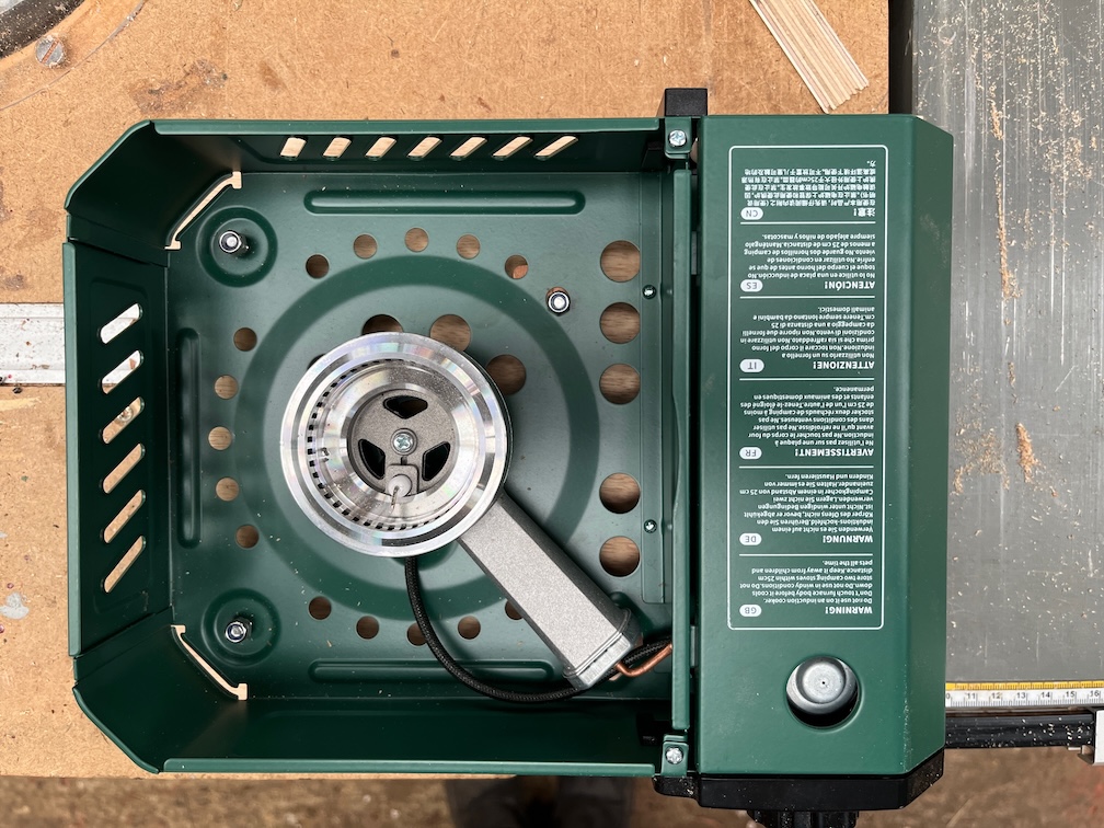
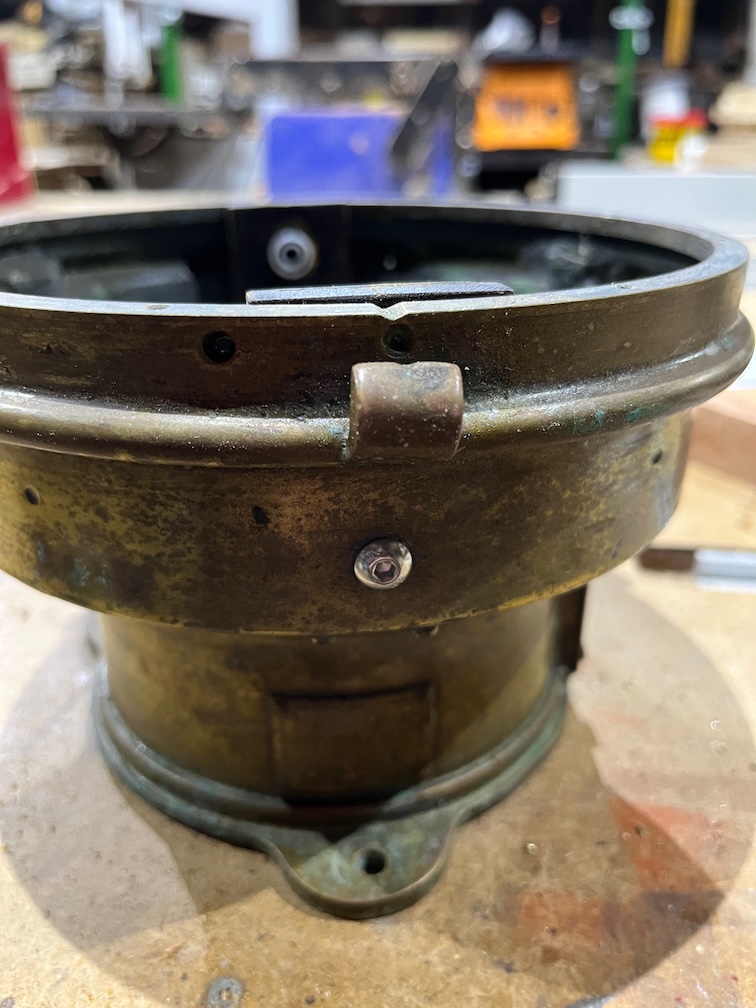
While I was down at the workshop and still had break time left, I bolted the galley stove to the support board and the galley stove task is completed.
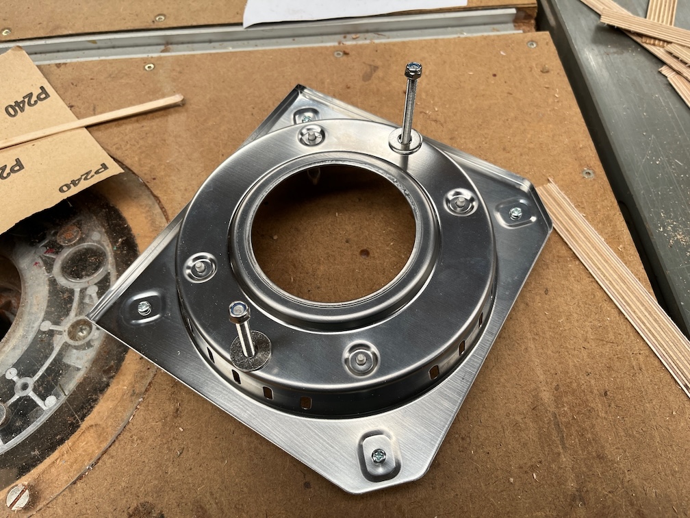
I had a useful arrival for Shoal Waters just before lunch, a cast iron flame spreader.
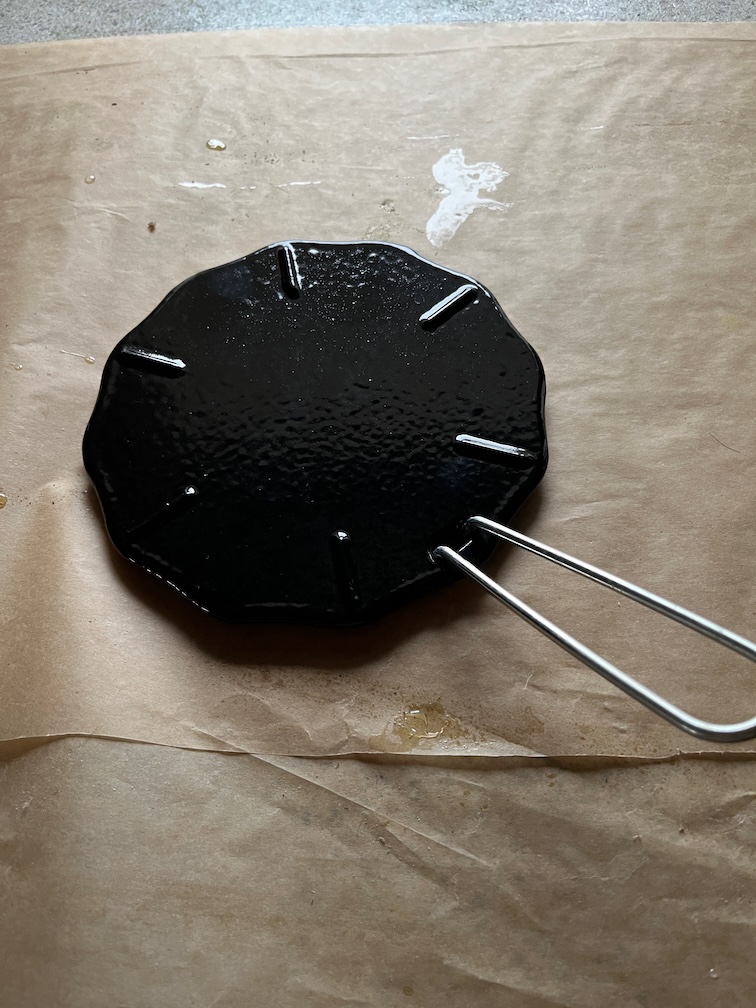
This is the item and a very useful device it is for portable gas stoves (PGS). You see, the main problem with cooking on a PGS is that you tend to use camping or hiking pots and pans, usually made of aluminium of stainless steel, but all very thin metal.
Okay, so I do have a medium sized cast iron frying pan on Naiad, but that’s beside the point.
The issue is that it is unbelievably easy to burn everything, the thin base of the pots does not conduct the heat away from the flame much, so you get a very hot spot in the centre of the pan and a much cooler area around the edges.
Try cooking porridge on a PGS in a thin bottomed pot and you’ll soon see what I mean.
This also happens with the alcohol burner stove I have on Naiad and I have one of these flame spreaders on her as well.
The flame spreader does just exactly what it says with the result that you get a pretty evenly spread heat right across the 170 mm diameter of the spreader. I have found that it really works well on Naiad and since I like porridge, I got one for Shoal Waters as well.
There are three problems with it. Firstly, it takes a bit longer to start cooking since you have to heat up the spreader first. Secondly, it gets hot enough to scorch wood so you need to leave it on the stove until it is cool. Thirdly, the handle, which you take off when using the spreader, gets hot very quickly when you put it into the spreader to lift it off the stove, hand burning hot. I’ll see if I can make some kind of heat resistant covering for the handle.
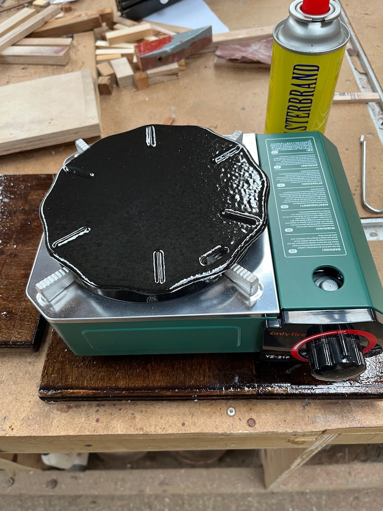
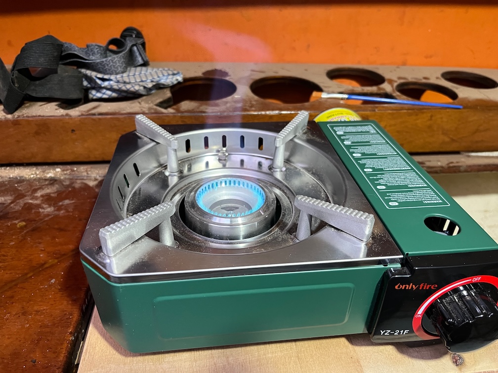
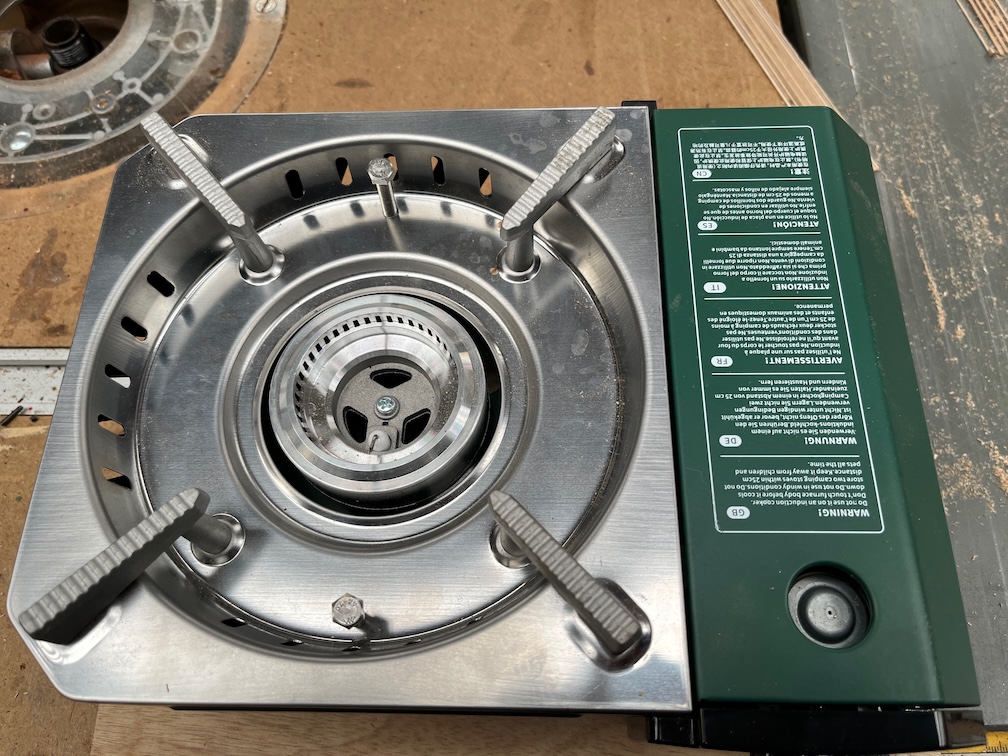
It is a great fit on Shoal Waters’ new gas stove, as you can see.
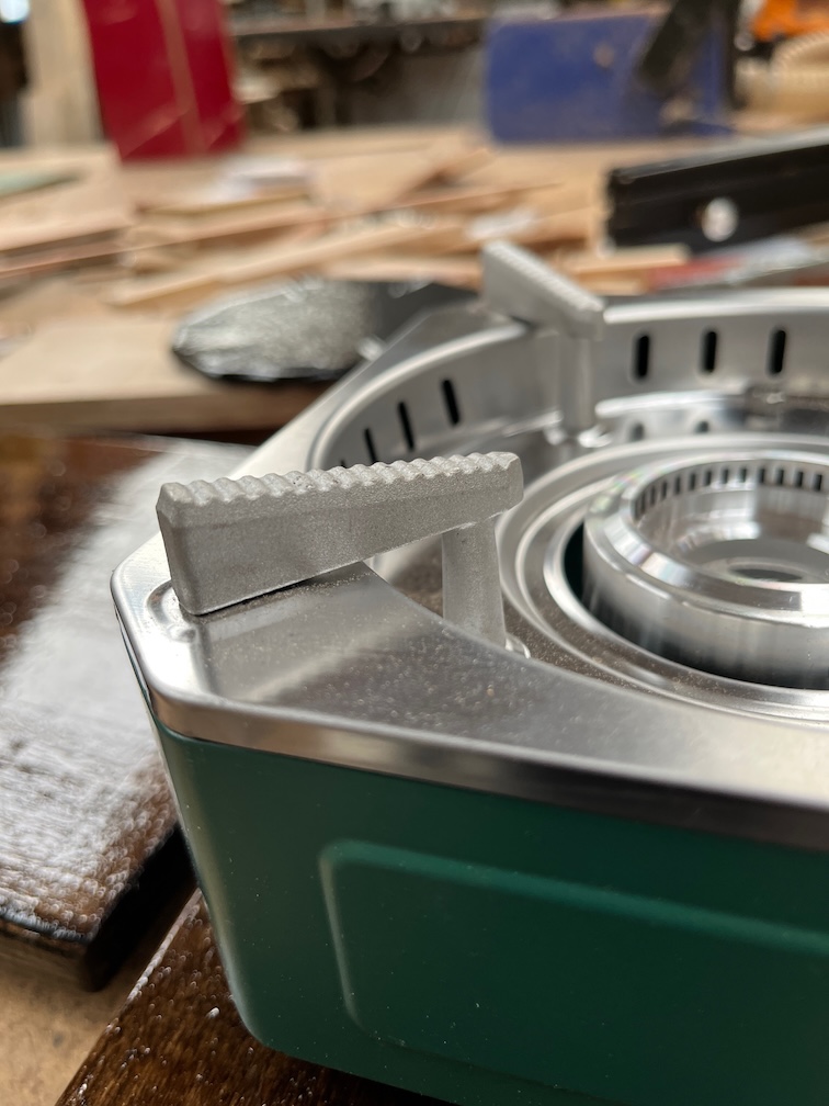
The pot holders on this stove are stepped and this makes the stove top fairly non-slip.
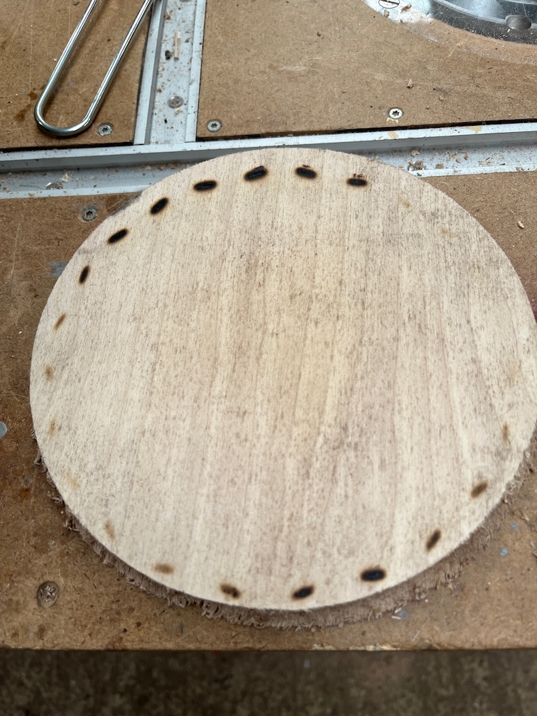
I boiled a kettle of water and then put the spreader on a piece of wood, just to see how bad the scorching was and as you can see, it’s not good. Several of the charred spots you can see here were smoking.
Still, with the spreader fairly well secured on the stove by the stepped pot stands, I don’t think this is going to be too much of a problem. If it becomes one in the future, I’ll try something else. A ceramic trivet, for example.
Time for a cup of tea.
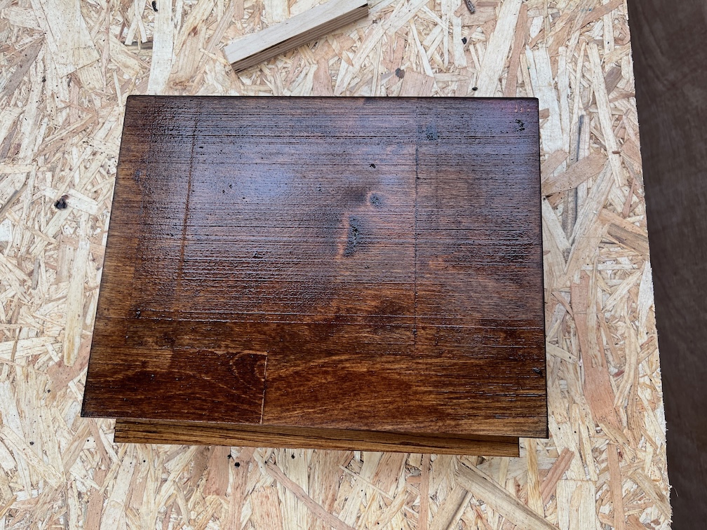
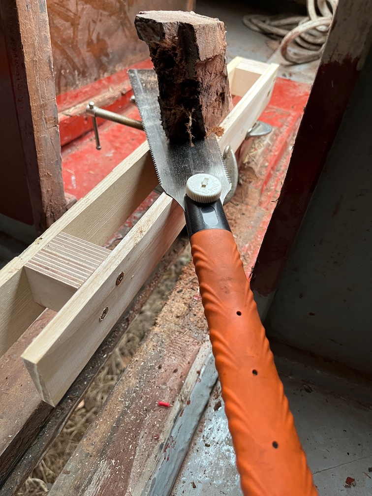
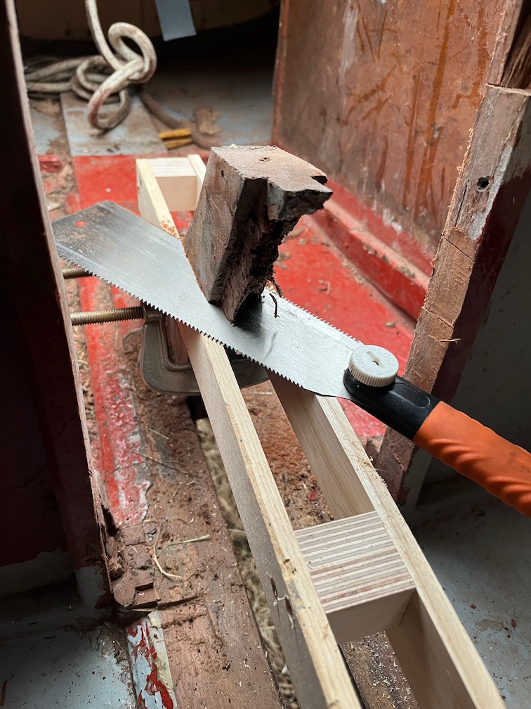
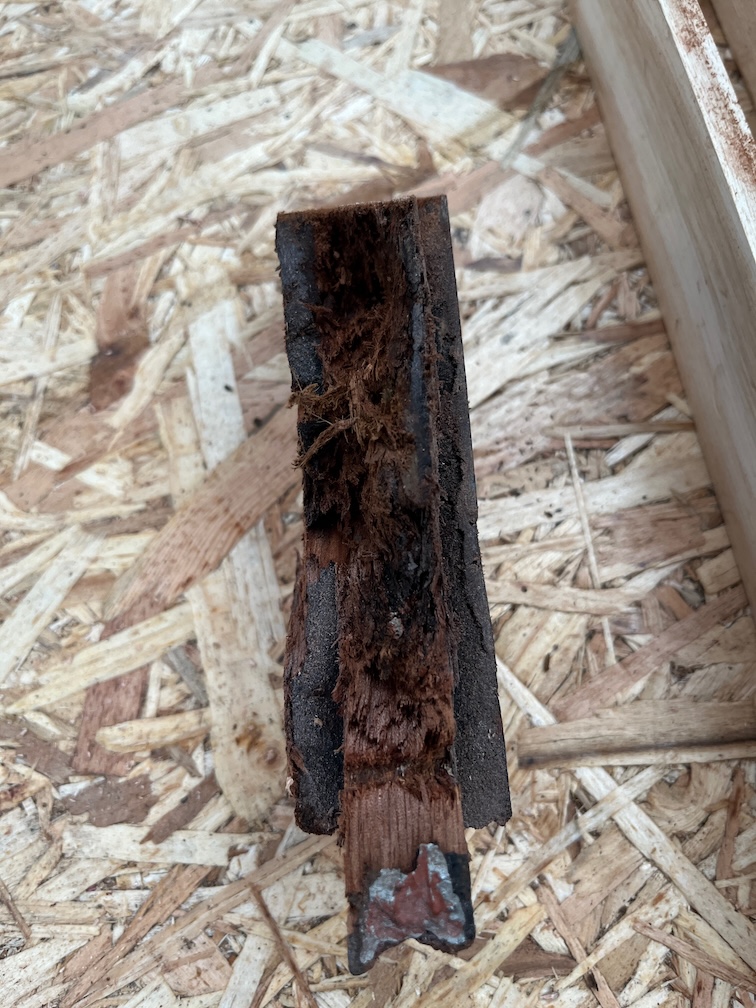
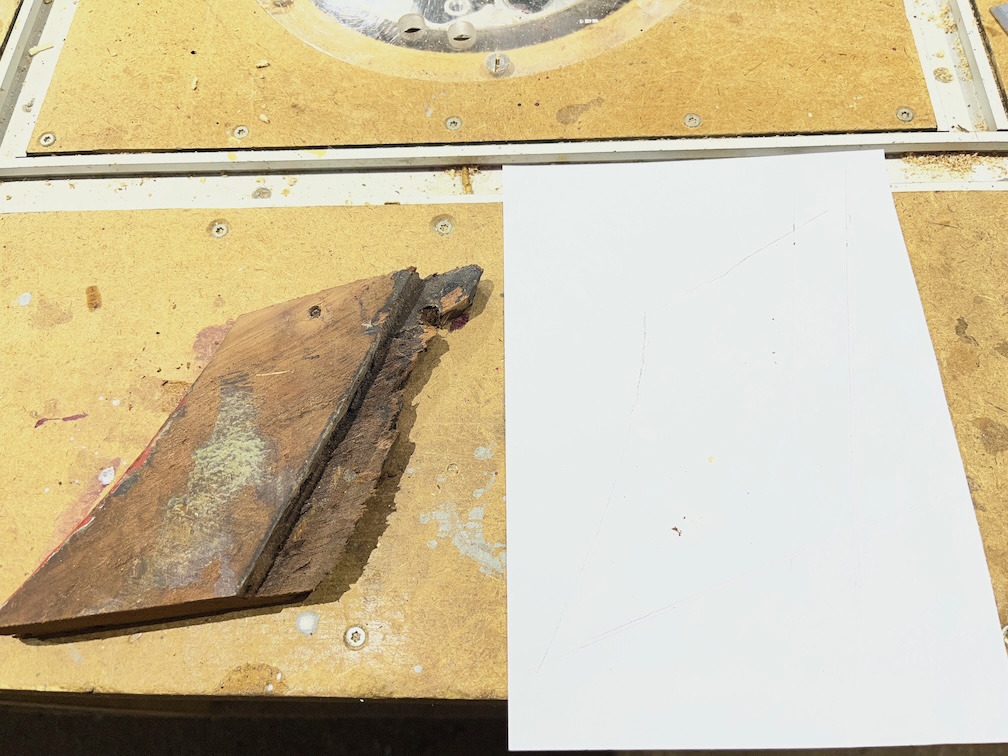
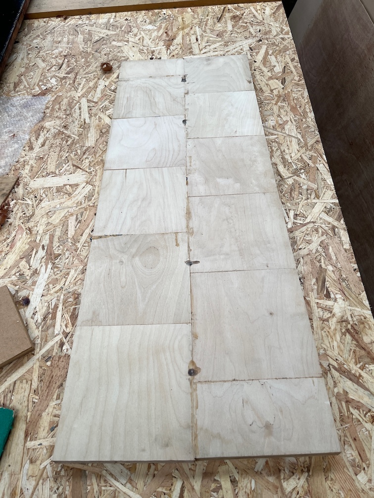
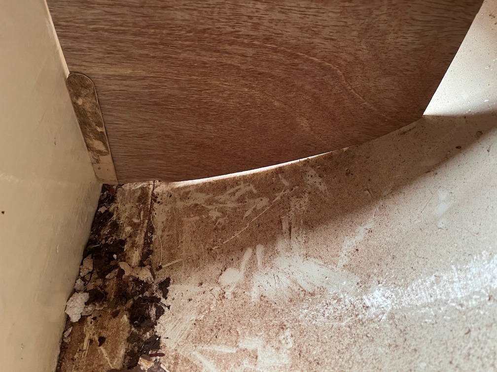
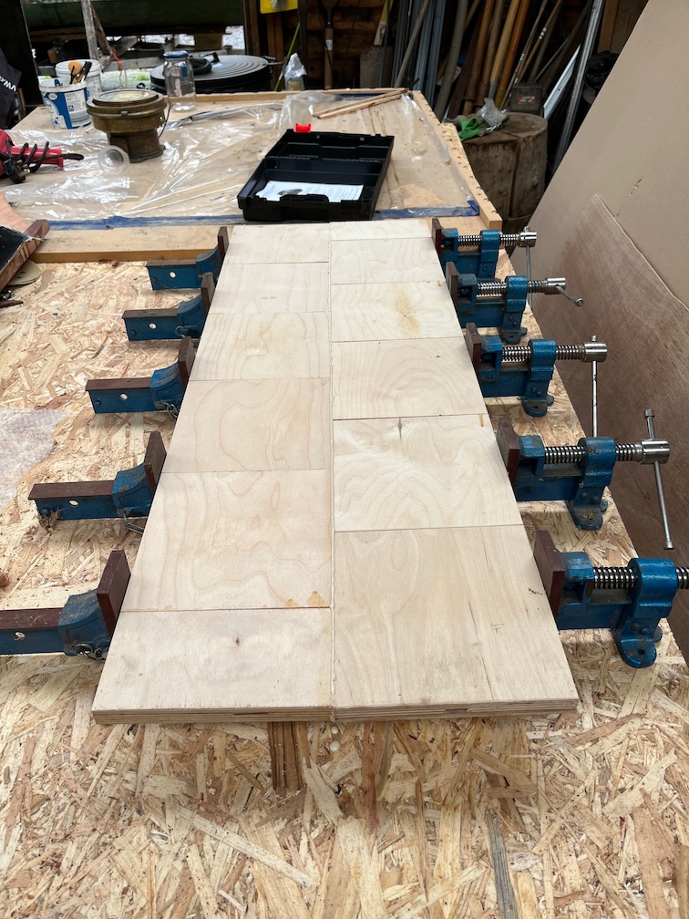
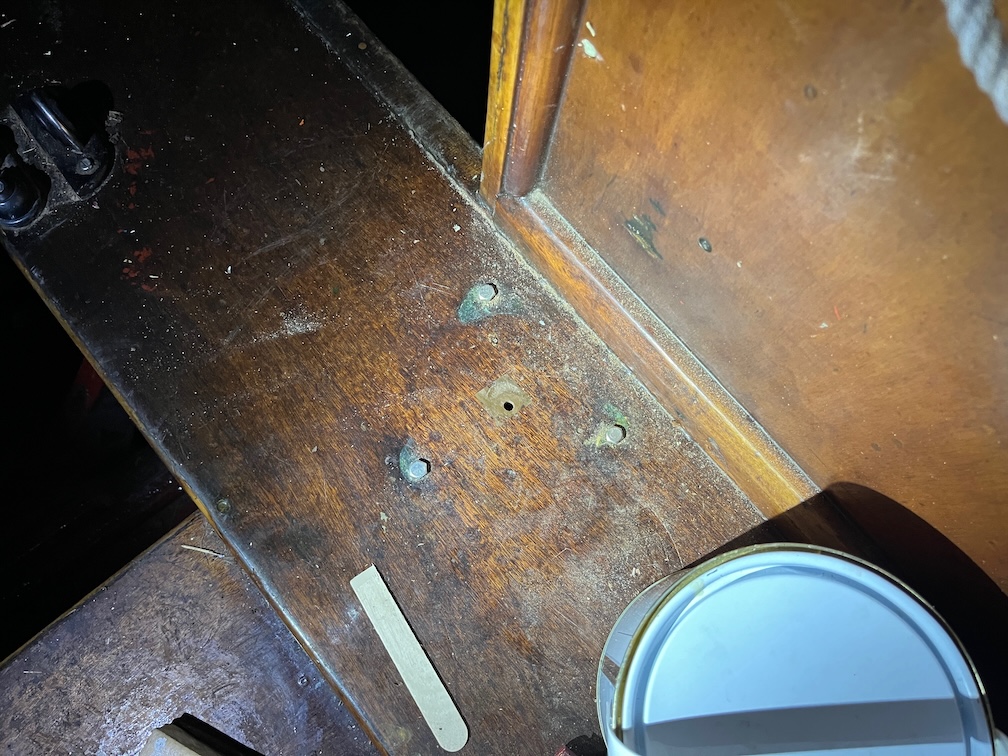
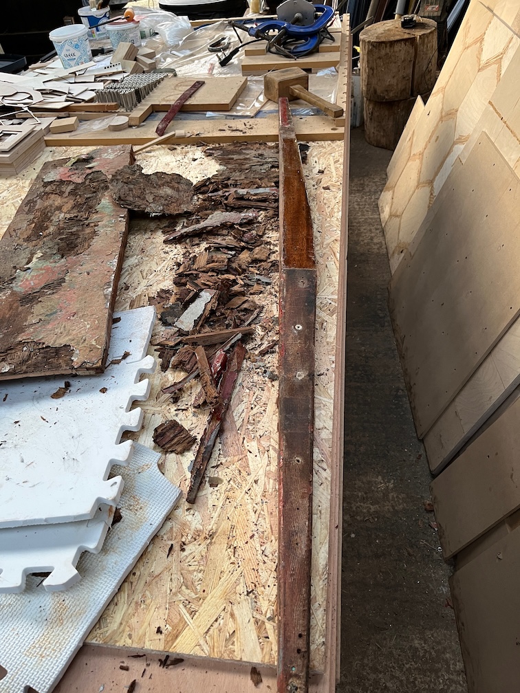
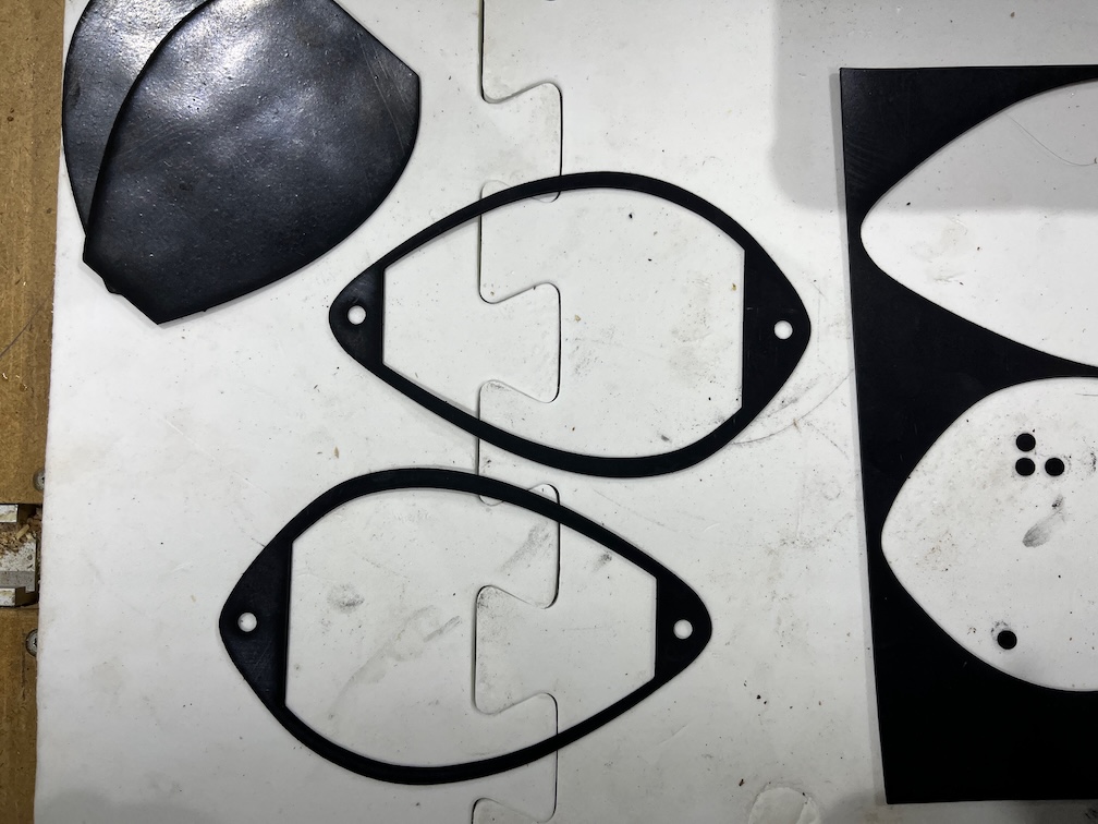
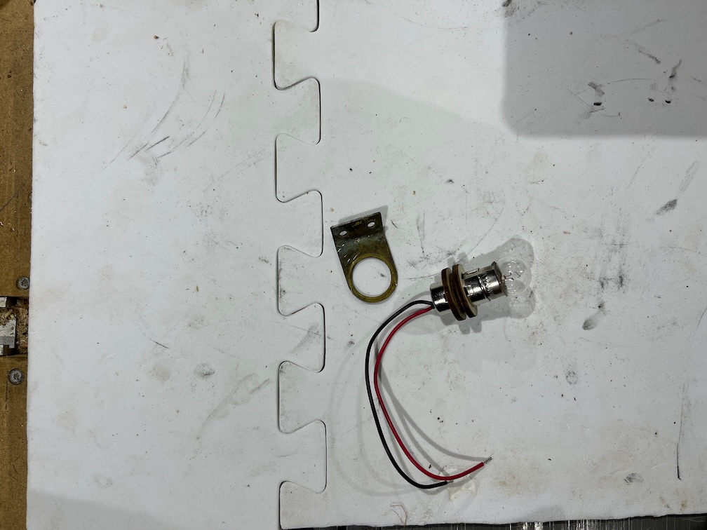
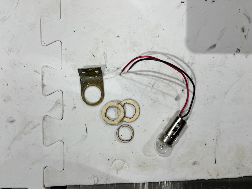
Finally, for today since the temperature is falling fast and affecting my fingers, again, I decided to tidy up a few of the pieces of Shoal Waters that I’ll be putting back in the places from which they were removed.
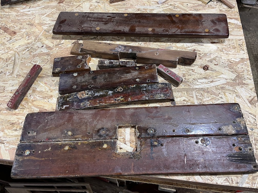
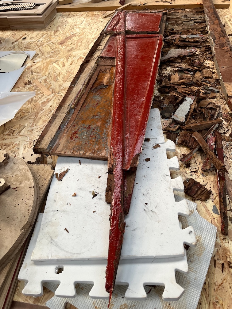
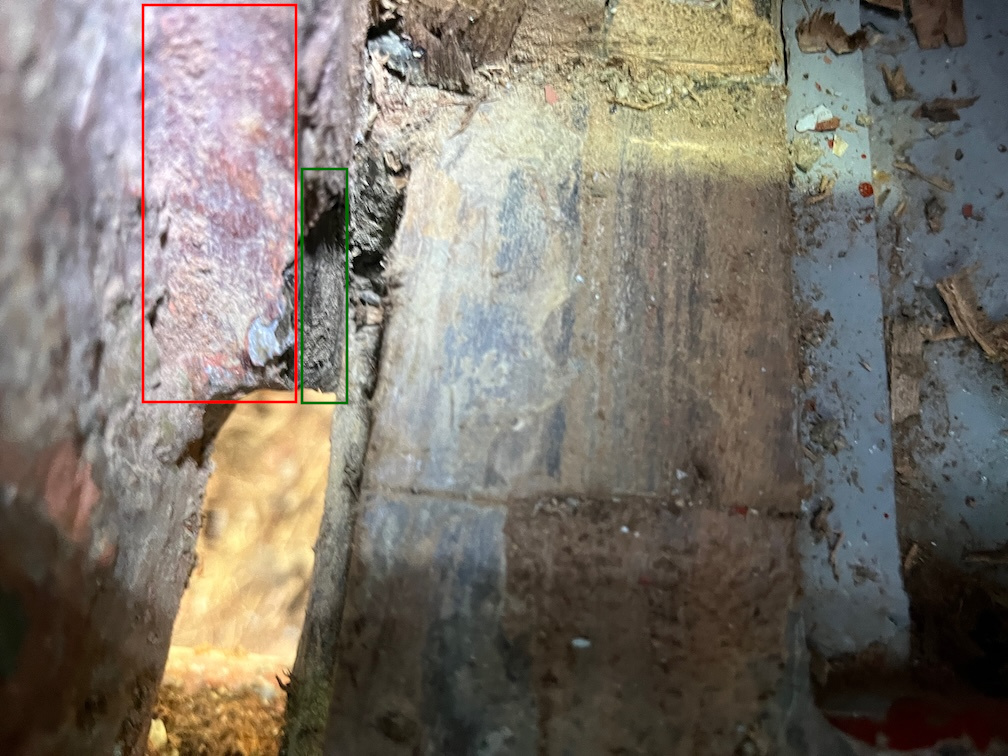
It is a simple task, just remove any loose varnish and sealant, check the edges for splinters and repair anything that needs it. This lot are fairly sound, mainly cosmetic damage.

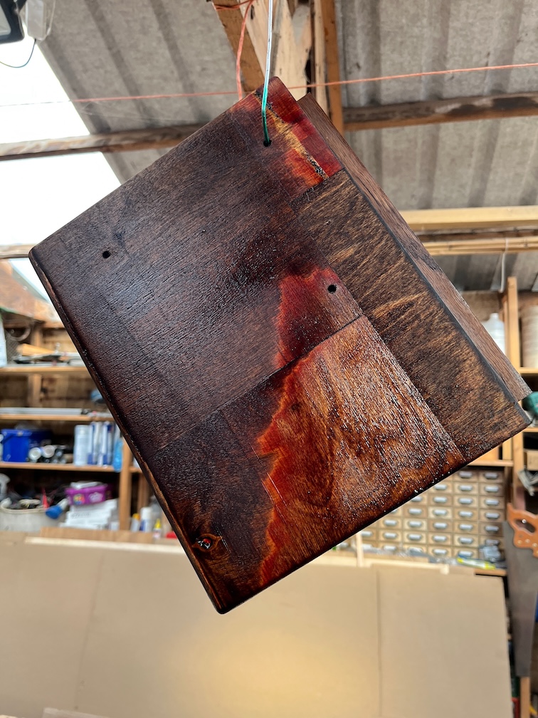
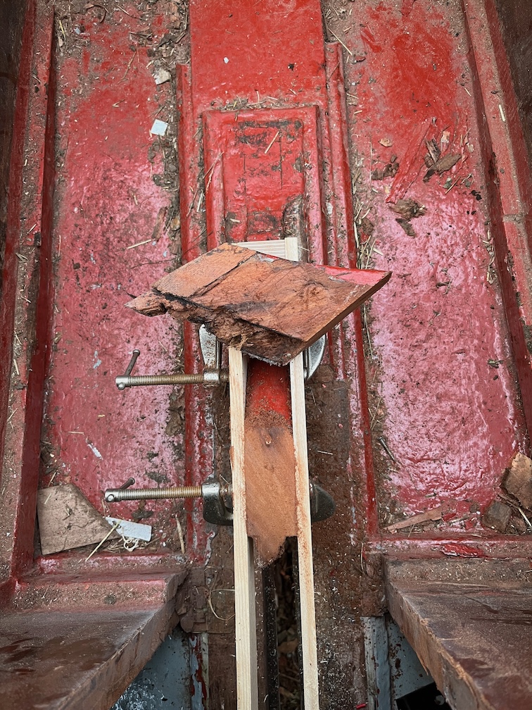
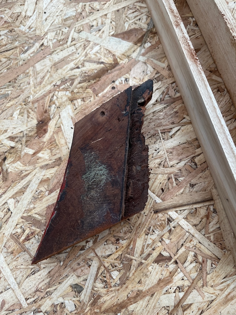
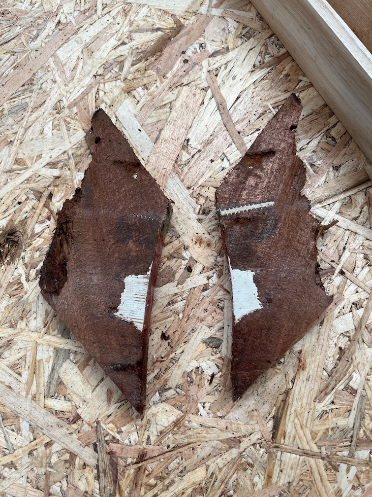
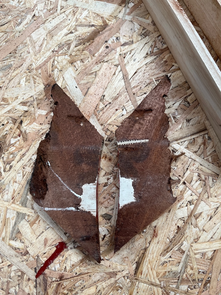
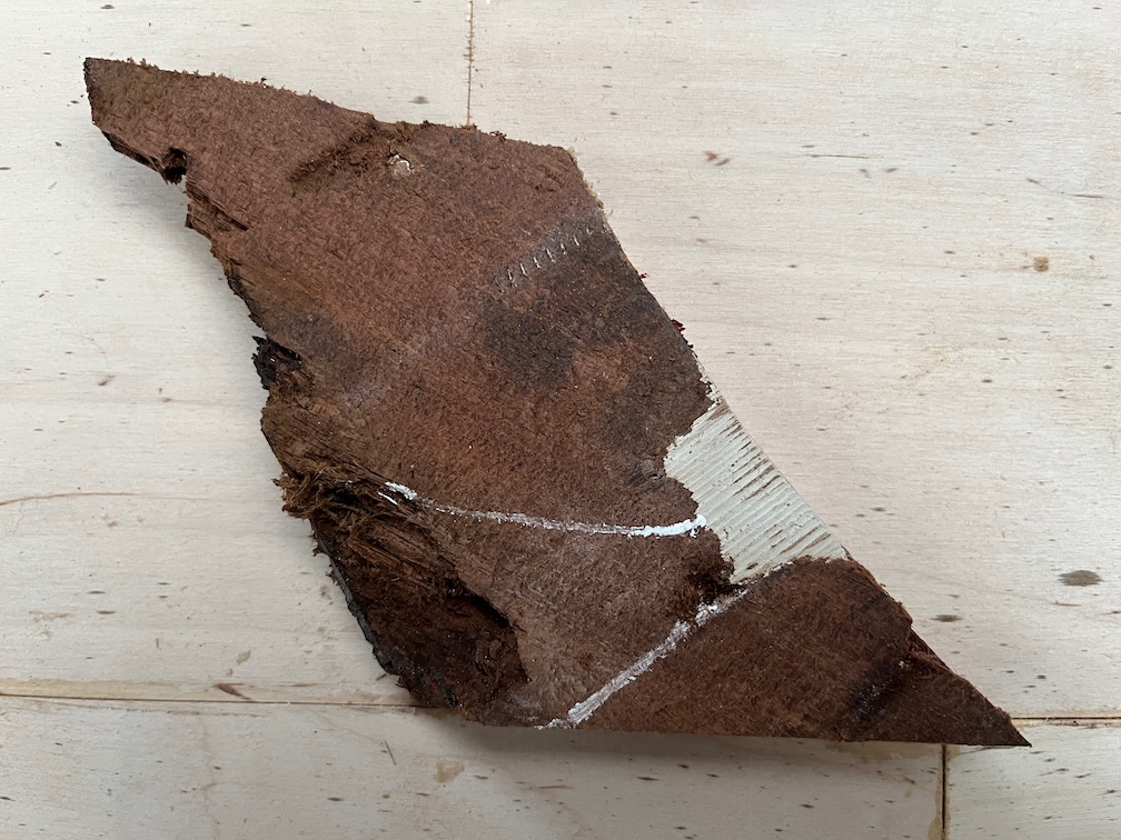
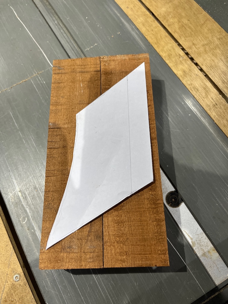
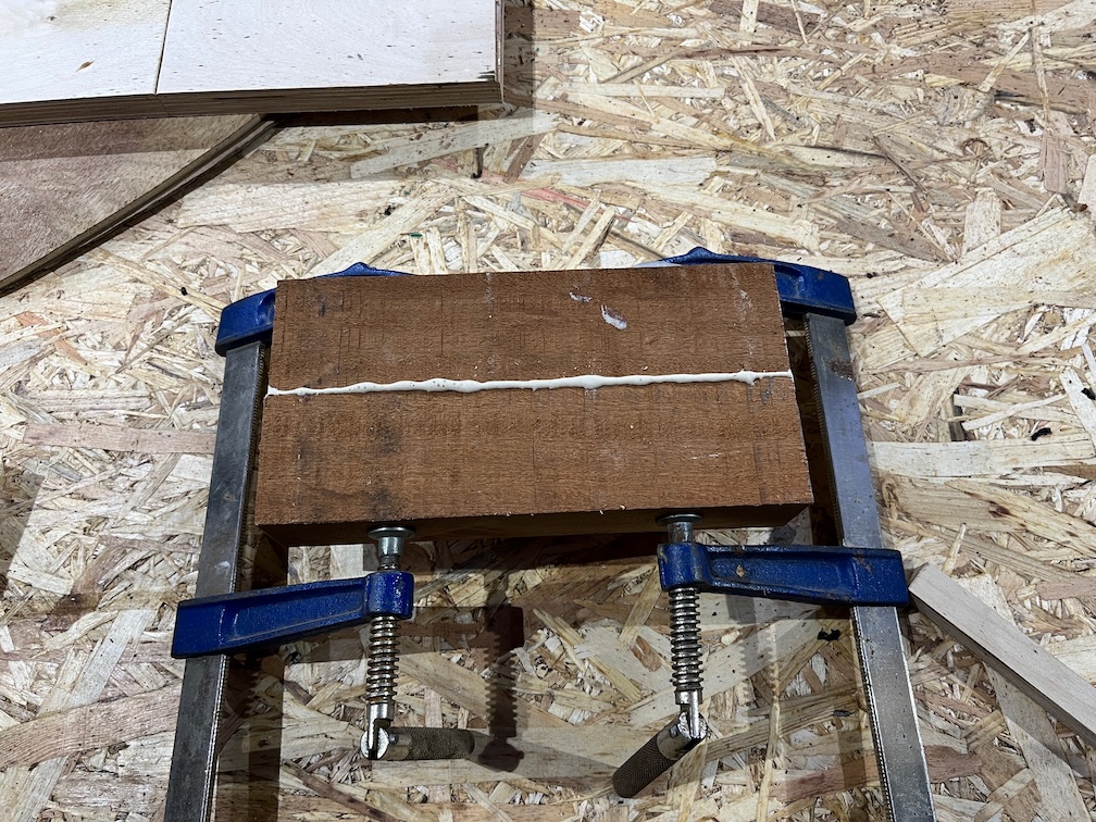
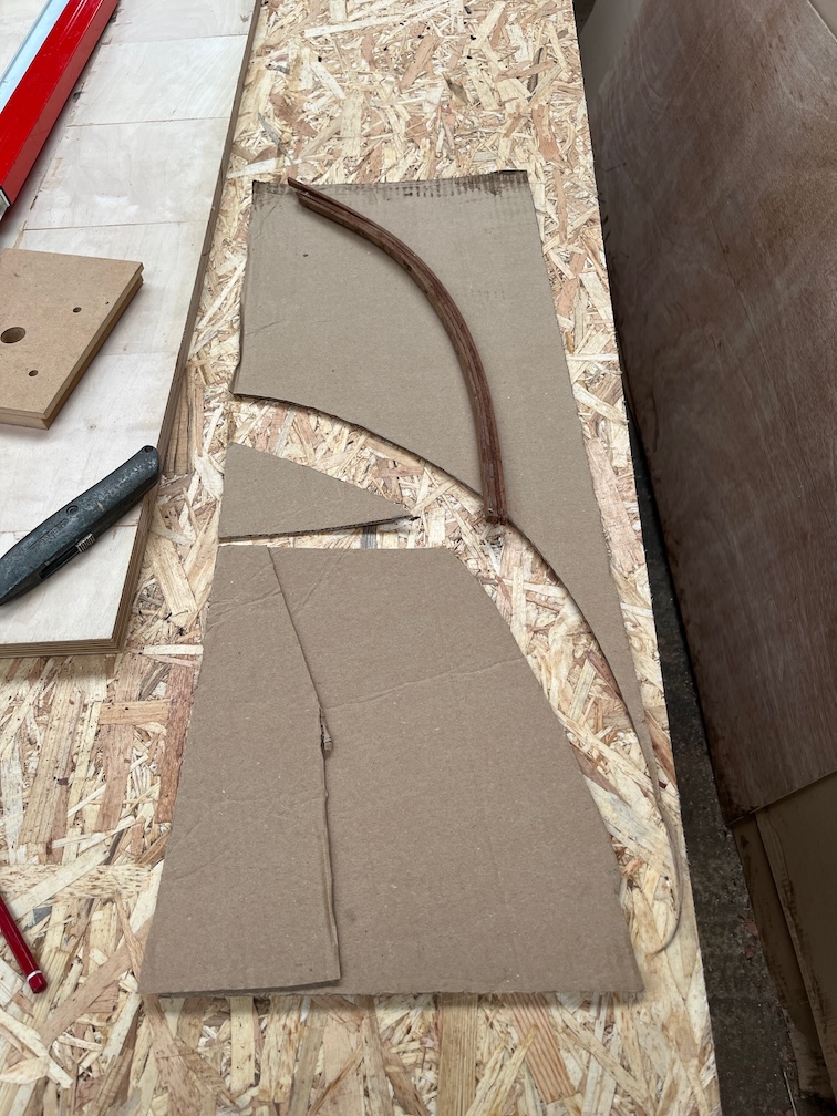
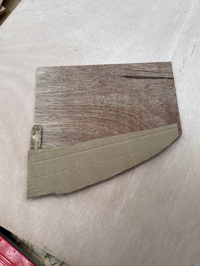
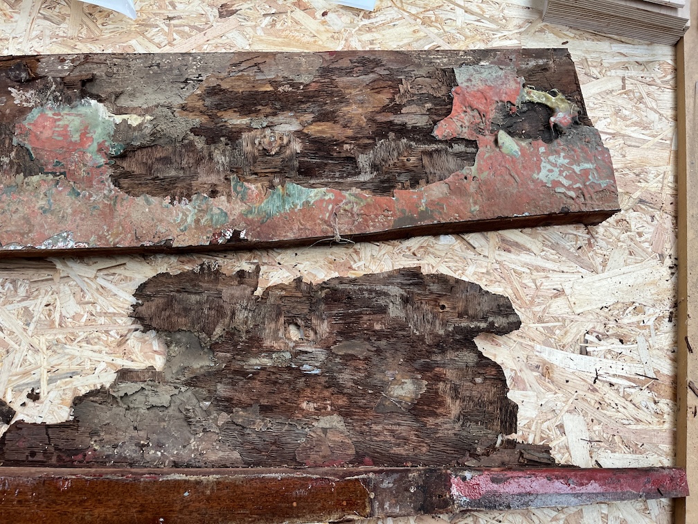
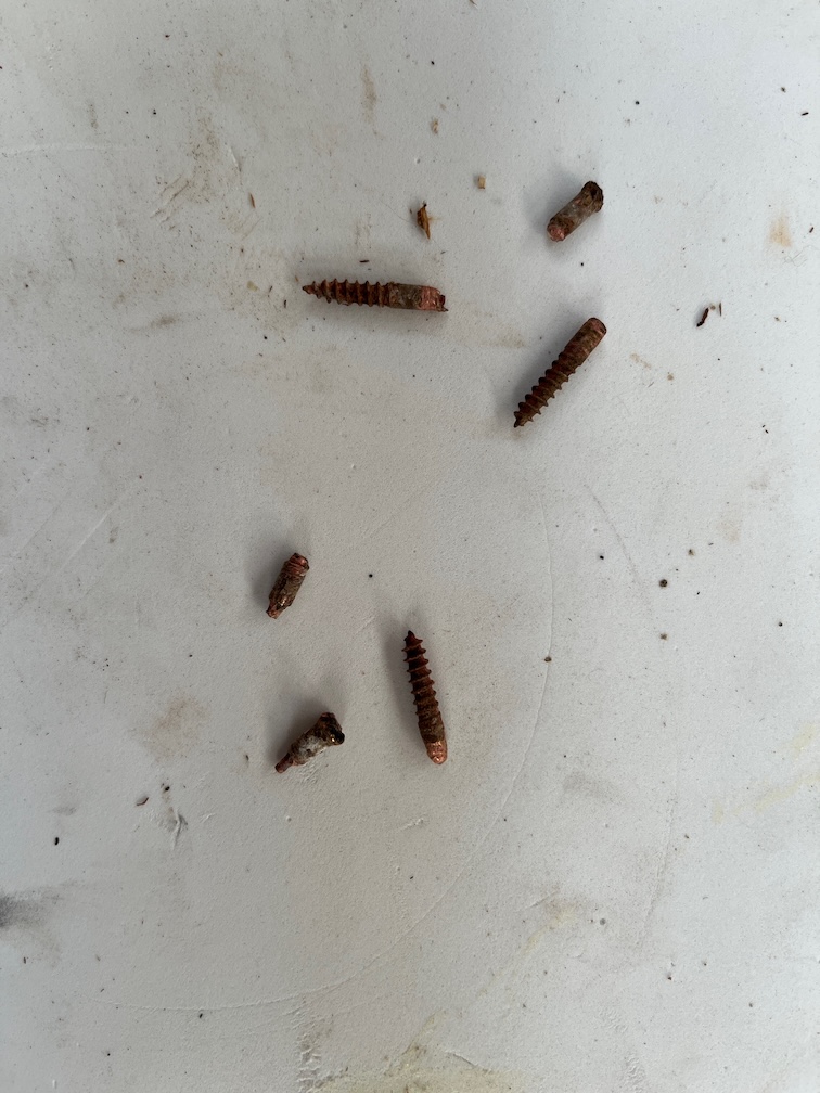
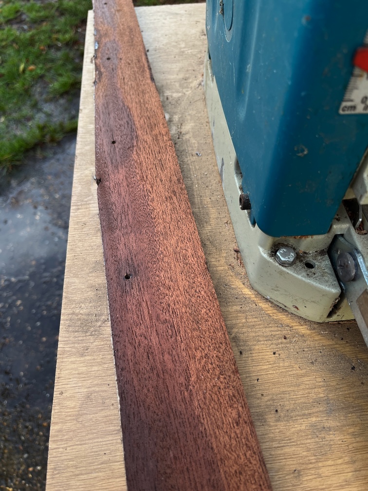
These however needed additional work. Old screw holes were drilled out and plugged in the case of the grey piece, the other pieces need to be dried out, sealed with Clear Penetrating Epoxy Sealer and two of the pieces need to be glued back together.
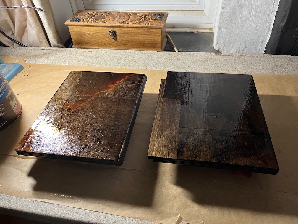
If the wood dries out before I turn in for the night then I’ll apply the CPES, otherwise it will be a task for tomorrow.
Time for a cup of tea.